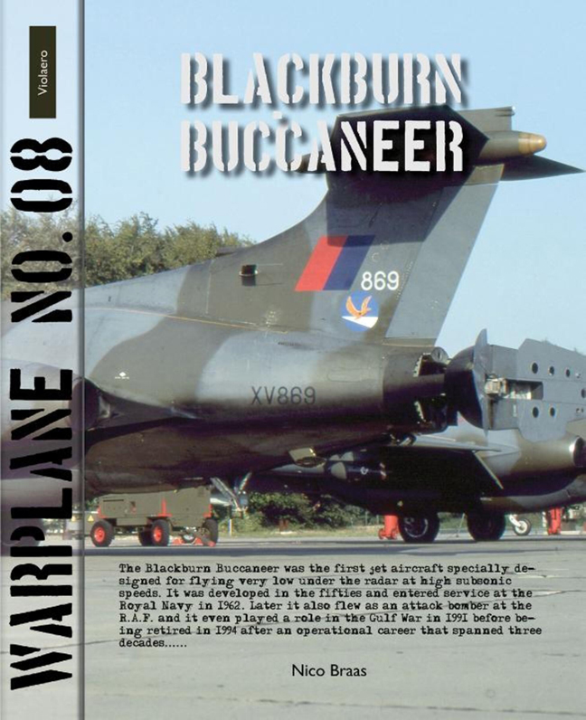
Book contents
- Frontmatter
- Introduction
- In service at the royal navy
- Buccaneer Photo-Recce crate
- South African nuclear bombers
- In service at the R.A.F. … at last
- Martel Missile (AJ.168) (AS.37)
- WE177 nuclear bomb
- The Buccaneer goes to war
- Museum piece
- Final phase out and retirement
- Sub-versions S.2:
- Accidents and Incidents
- Survivors
- Technical Description
- References
- Credits
Summary
The fuselage of the Buccaneer was designed using Whitcomb’s area rule technique, which had the effort of reducing drag while travelling at high subsonic and transonic speeds, and gave rise to the characteristic curvy “Coke bottle” shape of the fuselage. The majority of the airframe and fuselage was machined from solid casting to give great strength to endure the stress of low level operations. Considerable effort went into ensuring that metal fatigue would not be a limiting factor of the Buccaneer’s operational life even under the formidable conditions imposed of continuous low level flight. A large split air brake was built into the tail cone of the aircraft. The hydraulically operated air brake formed two leaves that could be opened into the air stream to quickly decelerate the aircraft. The style of air brake chosen by Blackburn was highly effective in the dive-attack profile that the Buccaneer was intended to perform, as well as effectively balancing out induced drag from operating the BLC system. It featured a variable incidence tail-plane that could be trimmed to suit the particular requirements of low-speed handling or high-speed flight; the tail-plane had to be high mounted due to the positioning and functionality of the Buccaneer’s air brake. The wing design of the Buccaneer was a compromise between two requirements: a low aspect ratio for gust response and high aspect ratio to give good range performance. The relatively small wing was suited to high-speed flight at low altitude; however, a small wing did not generate sufficient lift that was essential for carrier operations. Therefore, BLC (Boundary Layer Control) was used upon both the wing and horizontal stabilizer, having the effect of energising and smoothing the boundary layer airflow, which significantly reduced airflow separation at the back of the wing, and therefore decreased stall speed, and increased effectiveness of trailing edge control surfaces including flaps and ailerons. For use on aircraft carriers the complete nose and tail sections could be swivelled 180°. Reason for this was that the aircraft had to fit in the aircraft carrier’s lift.
- Type
- Chapter
- Information
- Blackburn Buccaneer , pp. 47Publisher: Amsterdam University PressPrint publication year: 2014

