Introduction
One means of preventing areas from being hit by avalanches is to divert the flow by straight or curved walls or tetrahedral or cylindrical-type structures. However, shock formations are generated within these flows. They give rise to a transition from super- to subcritical flows of the granular avalanche, associated with depth and velocity changes. The Savage-Hutter theory, a hyperbolic system of equations, has the potential to capture the internal shock formation if the equations are integrated with appropriate shock-capturing integration techniques. In this paper the equations are first presented, then experiments show how shocks are formed which can be simulated by the shock-capturing technique. Finally, an application of avalanche protection in the laboratory as well as its simulation is demonstrated.
Governing Equations
In the extended Savage-Hutter theory (Reference LangLang, 1991; Reference Wieland, Gray and HutterWieland and others, 1999) the flow avalanches are mathematically described as incompressible fluids which flow over complex topography. An orthogonal curvilinear coordinate system, Oxyz, is introduced by a reference surface that follows the mean downslope chute topography (see Fig. 1) (Reference LangLang, 1991; Reference Wieland, Gray and HutterWieland and others, 1999). The x axis is oriented in the down-slope direction, the y axis lies in the cross-slope direction to the reference surface and the z axis is normal to it. The down-slope inclination angle of the reference surface ζ changes as a function of the downslope coordinate x, and there is no lateral variation in the y direction. The complex shallow basal topography is defined by its elevation z = zb(x,y) above the reference surface, as illustrated in Figure 1.
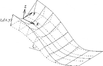
Fig. 1. The curvilinear reference surface (dashed line) which defines the curvilinear coordinate system, Oxyz, where the down-slope inclination angle of the reference surface, ζ to the horizontal, changes as a function of the downslope coordinate x, and there is no lateral variation in the y direction. The complex shallow basal topography is defined by its elevation z = zb(x, y) above the reference surface, as illustrated in Figure 1.
During flow the rheological behaviour obeys a Mohr-Goulomb-type plastic flow law with a constant internal angle of friction φ. Scaling analysis isolates the physically significant terms in the governing equations and identifies those terms that can be neglected. These equations are further simplified by integrating them over the avalanche thickness. What emerges is a free boundary value problem for the avalanche depth and the two velocity components parallel to the bed. The leading-order, depth-integrated mass balance takes the conservative form

where h is the avalanche thickness and u and v are the velocity components in the down- and cross-slope directions, respectively. The leading-order, depth-integrated momentum-balance components are
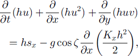
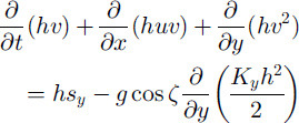
in conservative form, where g is the gravitational acceleration, ζ(x) is the local slope inclination angle, and Kx and Ky are the down- and cross-slope earth pressure coefficients defined by the Mohr-Coulomb criterion. The terms sx and sy represent the net driving accelerations in the down- and cross-slope directions, respectively:


which are combinations of the gravity acceleration, basal drag and basal topography gradients terms. | v | = (u2 + u2)1/2 is the modulus of the velocity components, 6 is the basal Coulomb dry-friction angle and K = –∂(/∂x is the local curvature of the reference surface. Earlier versions of these equations were also derived by Reference LangLang (1991). However, the equations by Reference LangLang (1991) are not equivalent to the upper equations in conservative form, and these equations in conservative form are applied for numerical simulation here to describe the shock formation.
The earth pressure coefficients Kx and Ky link the normal pressures in the down- and cross-slope directions with the overburden pressure, Kx = pxx/pzz and Ky = pyy/pzz. For avalanches whose motion is predominantly in the down-slope direction Reference Hutter, Siegel, Savage and NohguchiHutter and others (1993) showed that

The subscripts “act” and “pass”, respectively, denote active and passive stress states, which become effective when the avalanche extends or contracts in either the down- or cross-slope direction (Reference Greve, Koch and HutterGreve and others, 1994):

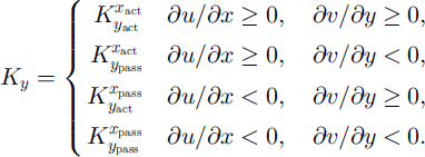
Active stress states are associated with a dilation of the material, whilst passive stress states are associated with a compression.
Since this Savage-Hutter theory is a hyperbolic system of equations, it possesses potential to describe the shock waves, which are observed in experiments. With appropriate shock-capturing integration technique for the Savage-Hutter equations, such shock formations can therefore be described well.
Formation of Shocks
Shock waves are generated when there is a change in the inclination angle during supercritical flow or when an obstacle is placed in the flow. For example, for a granular avalanche flow of a finite mass from an inclined plane to a horizontal run-out zone, shocks are formed in the transition region, where the velocity transfers from supercritical to subcritical flow states immediately before and at settlement. Such shocks have caused numerical instability in the Lagrangian numerical technique (Reference Hutter and KochHutter and Koch, 1991; Reference Greve and HutterGreve and Hutter, 1993; Reference Gray, Wieland and HutterGray and others, 1999; Reference Wieland, Gray and HutterWieland and others, 1999). Figure 2 shows this situation for the velocities simulated by the two-dimensional non-oscillatory central (NOC) scheme (Reference Jiang and TadmorJiang and Tadmor, 1997) inside the avalanche at dimensionless time t = 5,10,15, 20, 25. Here the material is suddenly released from a hemispherical cap with radius r0 = 1.85 dimensional length to slide on an inclined flat plane at 45° into a horizontal run-out plane connected by a smooth transition, 17.5 < x < 21.5. The arrows denote the direction of the velocity and their lengths indicate the speed. Since this shock-capturing scheme is implemented on a fixed stationary mesh, one cannot exactly point out the margin location. The region with depth h < 0.01 is regarded as material-free and the velocities are not shown here. The material is selected to possess the same internal angle of friction and basal friction angle, φ = δ = 35°. After opening the cap the front part of the avalanche body accelerates downslope due to gravity, whilst the rear part remains at rest because of the back pressure from the depth gradient, ∂h/∂x (t = 5,10). The avalanche body extends in the cross-slope direction, but the velocity in the downslope direction is obviously dominant. The front part comes to rest in the run-out zone, but the part of the tail accelerates further (t = 10). At t = 15 there is obviously a jump of velocity taking place at the transition zone, approximately at x = 21.5. This velocity jump corresponds to a thickness jump, and with the material approaching from the tail this jump propagates backwards (t = 20, 25).

Fig. 2. Velocities inside the avalanche body, where the arrows denote the direction of the velocity and their lengths indicate the speed. Motion is from left to right. After opening the cap the front part of the avalanche body accelerates downshpe due to gravity, whilst the rear part remains at rest because of the back pressure from the depth gradient, ∂h/∂x (t = 5, 10). The front part comes to rest in the run-out zone, but the tail part accelerates further (t = 10). At t = 15 a jump of velocity takes place at the transition zone, approximately at x= 21.5, which is coupled with a jump in thickness. With the material approaching from the tail part this velocity jump propagates backwards (t =20, 25).
Shock formations also occur when a rapidly flowing granular mass is diverted and redistributed by structural devices (fences or walls). For example, if a uniform layer of rapidly flowing granular material down an inclined plane is encountering a vertical wall forming an angle a with the direction of steepest descent (Fig. 3), then a straight shock will form at an angle β > α. Above the shock the undisturbed flow is supercritical with a thinner height and faster velocity; behind the shock it is subcritical with larger thickness and slower velocity. The situation is analogous to the sub- and supercritical flows in hydraulics of free-surface-channel flows. What is different is that behind the obstruction (wall) there is a region without material (granular vacuum). This could be applied for the design of an obstruction to prevent a structure from being hit by the avalanche.

Fig. 3. A uniform layer of rapidly flowing granular material moving down an inclined plane with supercritical downstream velocity is encountering a straight wall and inclined at angle a. (a) The induced cross-flow generates a shock inclined at angle β with layer thickness and subcritical velocity, (b) The photo shows this situation in the laboratory experiment.
Avalanche Protection
The Savage and Hutter theory is applied in the design of avalanche-protection constructions. Using the two-dimensional NOC scheme (Reference Jiang and TadmorJiang and Tadmor, 1997) for the Savage-Hutter equations, the determination of endangered zones of inhabited regions with a potential to be subjected to avalanches becomes possible. A proposal of protection against the avalanche for “Schneefernerhaus at Zugspitze” is the construction of a tetrahedral wedge (pyramid), which diverts the flow and guides the snow to pass the building on either side of it. The building is an old hotel renovated to a research laboratory for environmental and climatological research and situated at 2700ma.s.l on a rather flat (i.e. non-curved) mountain slope inclined by approximately 45°.
In the laboratory the experiments were performed with models of scale 1:100, where a metallic plane, 1 m wide and 1.2 m long, with inclination angle 45° to the horizontal is used as slope. A tetrahedral wedge (pyramid) composed of Styropor is set on this plane. If the x axis is aligned with the direction of steepest descent of the plane and the y axis points in the cross-slope direction, the upper peak of the base of the pyramid then lies at the point (4.0, 0.0), and the rear edge of its base lies along the line x =7.2 dm, (see Fig. 4). As “snow-plastic beads of 2.5 mm are used, which are characterized by an internal angle of friction </> = 37° ± 2° (Reference Hutter and KochHutter and Koch, 1991), and a basal angle of friction m = 25° ± 3° for the metal plane and s = 37° ± 3° for the Styropor wedge.

Fig. 4. Overview (left) of the sketch of the flow and the inclined flat plane with the protection structure (tetrahedral wedge). Side view (right) of the inched flat plane and the wedge.
Figure 5 (left) displays the photograph for a steady flow passing the tetrahedral defence structure on either side of it. An oblique shock is formed on either side of the defence structure, which can be clearly seen from the streamlines. Behind the wedge the flow rapidly spreads in the cross-slope direction and forms two expansion fans, between which a material-free region is formed which can be seen as the protected zone. Figure 5 (right) demonstrates a result simulated by the two-dimensional NOC scheme (Reference Jiang and TadmorJiang and Tadmor 1997), in which the boundary condition is selected to give a constant supercritical inflow, h = 0.3 and u = 0.6 (dimensionless) at the top (x = 0.0) and the outflow condition is presumed for the other boundaries (at x = 12.0 and y = ± 5.0). For the numerical instability from the jumps of the earth pressure coefficients (Equations (8) and (9)), a regularization is applied here (Reference Tai and GrayTai and Gray, 1998). The predicted flow thickness is given in contours of dimensionless length units at the dimensionless time t = 10, in which the flow is nearly stationary and the tetrahedral wedge is symbolically indicated by the dashed lines. The oblique shock on either side of the defence structure can be observed in the contour plot from the numerical simulation. Similarly, as in the experiment, behind the pyramid the flow rapidly spreads in the cross-slope direction, forming two expansion fans which are well described in the contour plot. Between the expansion fans the grain-free zone is viewed as the protected region.
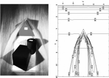
Fig. 5. Photograph (left) of the steady flow past an avalanche defence structure. The defence structure (tetrahedral wedge, in grey) protects the building (in black) where a material-free region (in white) is formed. The computed flow thickness (right) is illustrated at the dimensionless time t = 10 with contours of equal thickness, when the flow is nearly stationary. All lengths are in dimensionless units.
Conclusions
One means of preventing areas from being hit by avalanches is to divert the flow by straight or tetrahedron-type structures, which normally cause the shock formations. The Savage-Hutter theory as a hyperbolic system of equations has the potential to capture the shocks. Using a shock-capturing numerical scheme (e.g. the NOC scheme), the shocks can be well described subject to the shock formations around the obstacle as observed in the experiment. This technique can also be applied for the design of protection structures against avalanches.
Acknowledgements
This research was supported by the DFG project SFB 298 “Deformation und Versagen bei metallischen und granularen Strukturerf and SFB 256 “Nichtlineare Partielle Differentialgleichungen”at Bonn University. We thank K.-A. Lie of SINTEF Applied Mathematics, Oslo, Norway, for his NOC code for Euler equations in gas dynamics, which we used as a basis for our avalanche dynamics code.


