Introduction
In order to develop advanced materials solutions and improve predictive models, fundamental material responses to a broad range of external stimuli must be well understood [Reference Samaras1]. Systems under extreme temperatures, mechanical stresses, radiation flux, and other harsh conditions are of increasing interest for future engineering applications such as deep space exploration [Reference Ghidini2] and advanced nuclear reactors [Reference Murty and Charit3]. Individually these conditions present substantial challenges, though materials are rarely subjected to a single stressor. To capture synergistic effects that may arise in such environments, it is necessary to expose a material to a combination of relevant conditions to reveal the complex interactions among underlying mechanisms [Reference Misra and Thilly4].
The combination of sub-nm resolving power and applied stimuli make in-situ transmission electron microscopy (TEM) a powerful tool for exploring fundamental mechanisms in materials science [Reference Taheri5]. By coupling electron beam imaging with a variety of sample holders and external hardware, direct observation of how a material responds to coupled extreme conditions becomes readily accessible. Challenges associated with constructing hardware, conducting experiments, and interpreting results make in-situ TEM a dynamic and active area of research. The range of capabilities for in-situ microscopy has grown prolifically in recent decades, permitting nanomechanical testing during chemical reactions [Reference Sharma6,Reference Sharma7], ion irradiation for radiation damage studies [Reference Li8,Reference Hinks9], ultraviolet-visible light illumination for photocatalysis [Reference Miller and Crozier10], ultrafast high-resolution imaging for nanosecond-scale dynamic processes [Reference Lee11], and many others [Reference Taylor12–Reference White15].
Sandia National Laboratories is home to a heavily modified TEM, dubbed the In-situ Ion Irradiation TEM (I3TEM) [Reference Hattar16]. The integration of three ion accelerators, laser exposure, heating and cooling capabilities, mechanical testing platforms, and high-speed imaging capabilities make the I3TEM uniquely suited for exploring coupled extreme environments. We present an overview of the facility and available testing techniques along with a selection of novel results that highlight the unique capabilities of this facility.
Materials and Methods
Capabilities of the I3TEM at Sandia National Laboratories
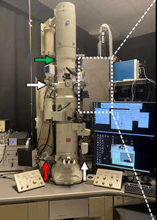
The I3TEM is a JEOL 2100-LaB6 microscope that has undergone constant evolution throughout the last decade. Figure 1a shows a photograph of the I3TEM with several of the recent additions highlighted. The green arrow in Figure 1a points to the “C0” lens, an externally controlled lens that operates between 1–18 V and precedes the first condenser lens to increase the electron beam current that reaches the sample [Reference Reed17]. The white arrows in Figure 1a point out two added connections to a Pfeiffer HIPace 400 turbomolecular vacuum pump that can move up to 355 liters s−1 of N2 to permit differential pumping of the pole piece region. This allows the column to remain at high vacuum while the specimen is exposed to different environments. The red arrow in Figure 1a indicates the beta version of the Integrated Dynamic Electron Solutions (IDES) Inc. Relativity system, which is coupled with a Direct Electron DE-16 4K camera system that alone has an acquisition frame rate of up to 4,237 frames per second. The Relativity electrostatic deflector permits controlled beam stepping at intervals as fast as 20 ns for capturing kilohertz scale videos [Reference Reed18].

Figure 1: a) The I3TEM. Highlighted with arrows are the differential pumping valves (white), the added C0 lens (green), Relativity electrostatic deflector system (red). The white box outlines the laser optics shown in b. b) The UV laser path (violet) and the IR laser path (yellow) are tracked. c) An electron ray diagram of the I3TEM showing the major lenses and apertures including the added C0 and electrostatic deflectors.
There are currently 27 TEM holders available at the I3TEM facility. A sampling of these holders includes, but is not limited to, heating, cryogenic cooling, tomography, mechanical testing and straining, gas or liquid cell, and electrical biasing. Additionally, a Nanomegas ASTAR precession-assisted automated crystallographic orientation mapping (ACOM) [Reference Rauch and Véron19] system has been outfitted to the I3TEM. Orientation maps reveal information about phases, crystallographic orientation, and local strain with a spatial resolution of ~8 nm. The I3TEM ACOM system has contributed substantially to the understanding of local changes observed upon application of stimuli in situ, for example, tracking the motion of individual grain boundaries under ion irradiation or fatigue loading [Reference Bufford20,Reference Bufford21].
The white dotted box in Figure 1a highlights the laser optics added to the microscope. These include a Quantel Ultra 20 ultraviolet (UV) laser directed at an exchangeable Ta filament to produce electron bursts for single-shot dynamic imaging and an SPI redEnergy G4 L-type 20W infrared (IR) laser for sample heating. Figure 1b is a schematic of the beam path for both the IR (yellow beam) and UV (violet beam). The 266 nm UV laser has a peak power density of 2400 J m−2. The 1064 nm IR laser has a beam spot diameter of approximately 80 µm, a pulse frequency of up to 1000 kHz, a pulse width that can be adjusted between 10–200 ns and can operate between 10–100% (2–20 W) of laser power. While the maximum attainable temperature of IR laser heating is highly material-dependent, 2100°C has been achieved during Sc2O3- stabilized ZrO2 experiments [Reference Grosso22]. The location of the additional electron optic components can be seen in the ray diagram of Figure 1c.
The ion irradiation capabilities are among the most differentiating features of the I3TEM, as there are only a limited number of facilities worldwide [Reference Hinks9]. Figure 2a shows the 6 MV Tandem Van de Graaff-Pelletron accelerator that produces a variety of ion species ranging from protons to Au, with energies between 800 keV to 100 MeV. The same range of ion species can also be directly extracted from the source (that is, without acceleration by the Tandem) in the range of 10–100 keV. An additional 1 MV Tandem accelerator, shown in Figure 2b, outfitted with a SNICS (source of negative ions by cesium sputtering) cathode [Reference Middleton23] was recently incorporated into the I3TEM facility. The beamlines from the two ion accelerators can simultaneously bombard bulk samples in an ex-situ chamber upstream of the TEM shown in the lower left corner of Figure 2c or be selectively introduced into the I3TEM (white arrow in Figure 2d). Low-energy ions can be produced from gaseous sources (protium, He, deuterium, N2, Kr, etc.) by the 10 kV G-1 Colutron accelerator (blue arrow in Figure 2d). These ions typically stop within a thin TEM foil and have enabled studies of bubble formation and cavity growth [Reference Taylor24,Reference Taylor25]. While the ion stopping range is material- and ion-dependent, implantation depths between 30 Å to 5 µm are achievable [Reference Ziegler, Biersack and Bromley26] with beam currents of ~10 pA to 50 nA from the Tandem accelerators and ~10 nA to 10 μA from the Colutron.
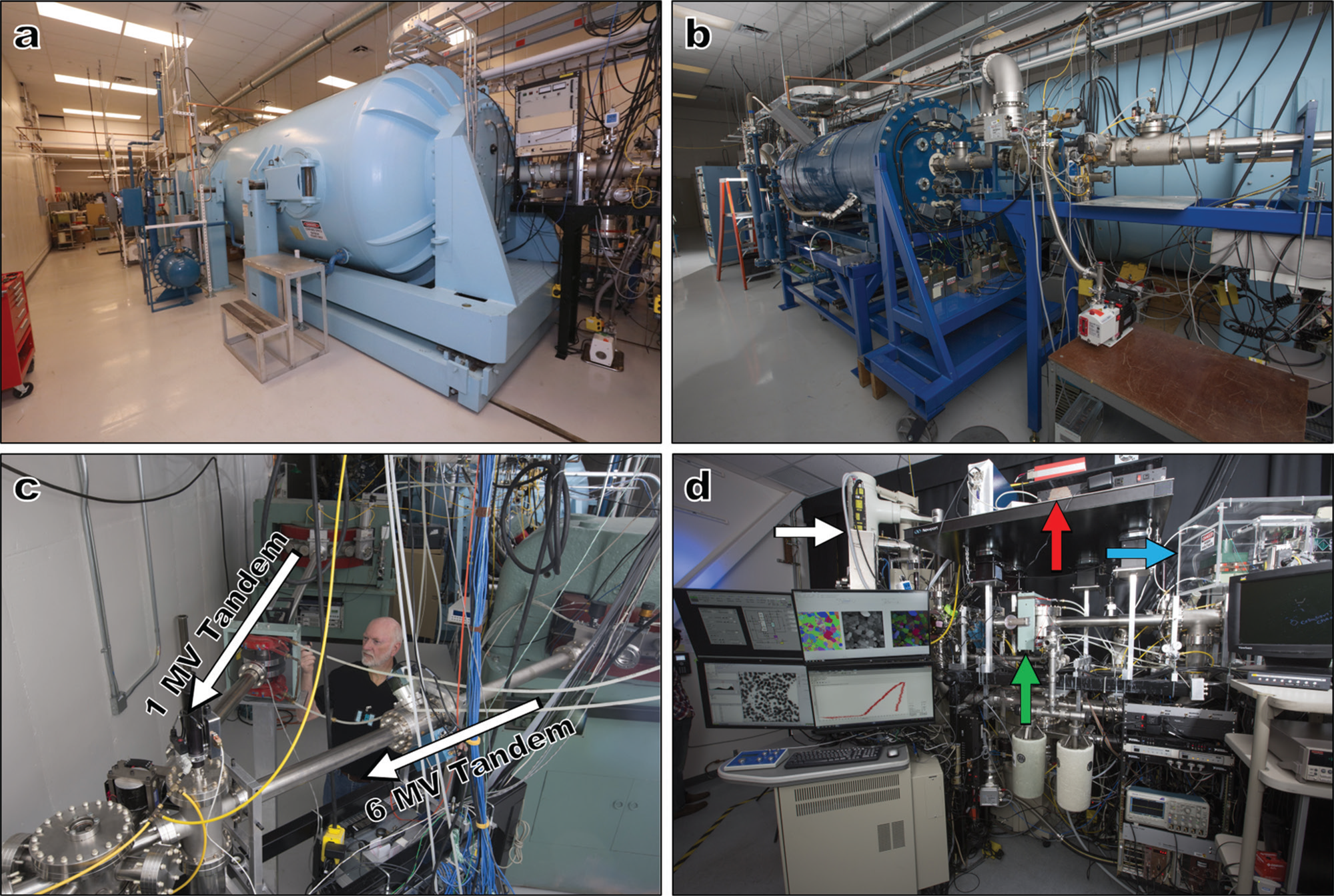
Figure 2: Photographs of the a) 6 MV and b) 1 MV Tandem ion accelerators. c) The beamline trajectories being directed into a mixing chamber before traveling into d) the TEM (white arrow). The green arrow indicates the location of the mixing magnet that combines the Tandem and Colutron (blue arrow) beamlines that permit triple-beam irradiation experiments, while the red arrow shows the laser control system.
In order to quantify and compensate for the impact of the TEM objective lens magnetic field on the trajectory of the low-energy light ions, a custom-built Hall probe TEM stage was developed to map the magnetic field over the entire tilt and translational range of the goniometer. Only the objective lens strength was found to impact the magnetic field with a maximum magnetic flux density of 11.6 kG. This knowledge combined with a mixing magnet (green arrow in Figure 2d) permits the simultaneous and concurrent in-situ TEM irradiation of a limited combination of ion irradiation conditions that have clear application in the nuclear sciences [Reference Taylor25].
Results
Multi-beam irradiation
Simulating radiation damage to materials in a nuclear reactor involves the combination of displacement damage, high temperatures, and the introduction of new transmuted elements. By performing simultaneous irradiation with multiple ion species in a controlled environment, it is possible to: 1) alter the displacement damage profile in a highly controlled manner [Reference Taller27], 2) modify the elemental species ratio [Reference Wang28], and 3) introduce localized heating [Reference Parry29]. This systematic approach within a TEM permits the elucidation of fundamental mechanisms that govern the evolution of materials during fission or fusion processes.
The three-ion beam fluences and fluxes into the I3TEM can be individually tailored to replicate many distinct environments, while also permitting for pedagogical conditions beyond what is expected in practical settings. Displacement damage typically manifests in bright-field TEM micrographs as “black spots” of varying size and shape that arise from the strain fields surrounding irradiation-induced defects. Defect contrast depends on the relative orientations of the electron beam, grain, and Burgers vector for each defect. Hence, detailed characterization is difficult during in-situ irradiation due to sample movement and continuously evolving defect structures. This difficulty can be overcome by selecting grains of comparable orientation and making qualitative comparisons of the density and size of black spots. Figure 3 demonstrates the wide range of radiation effects in a sputter-deposited Au film (Figure 3a) resulting from different combinations of incident ions. Irradiating with light ion species such as He (Figure 3b, ~2.3 × 10¹⁷ ions cm−2), molecular deuterium (D2, Figure 3c, ~5.9 × 10¹⁵ ions cm−2), or both simultaneously (Figure 3d, combined fluence ~3.9 × 10¹⁷ ions cm−2) at room temperature produces very little black spot damage [Reference Chisholm30]. Some mottling of the background was observed, possibly due to the local variation in strain or changes to the surface of the film. In other work performed in the I3TEM facility, continued irradiation by light ions resulted in the formation and gradual growth of small bubbles over a period of tens of minutes [Reference Taylor25,Reference Chisholm30]. In contrast, the impact of even a single Au ion creates a damage cascade that generates clearly observable black spot damage, as can be seen in Figure 3e (~2.1 × 10¹⁴ ions cm−2). These spots are indicative of larger defect structures, such as dislocation loops and stacking fault tetrahedra (SFTs).
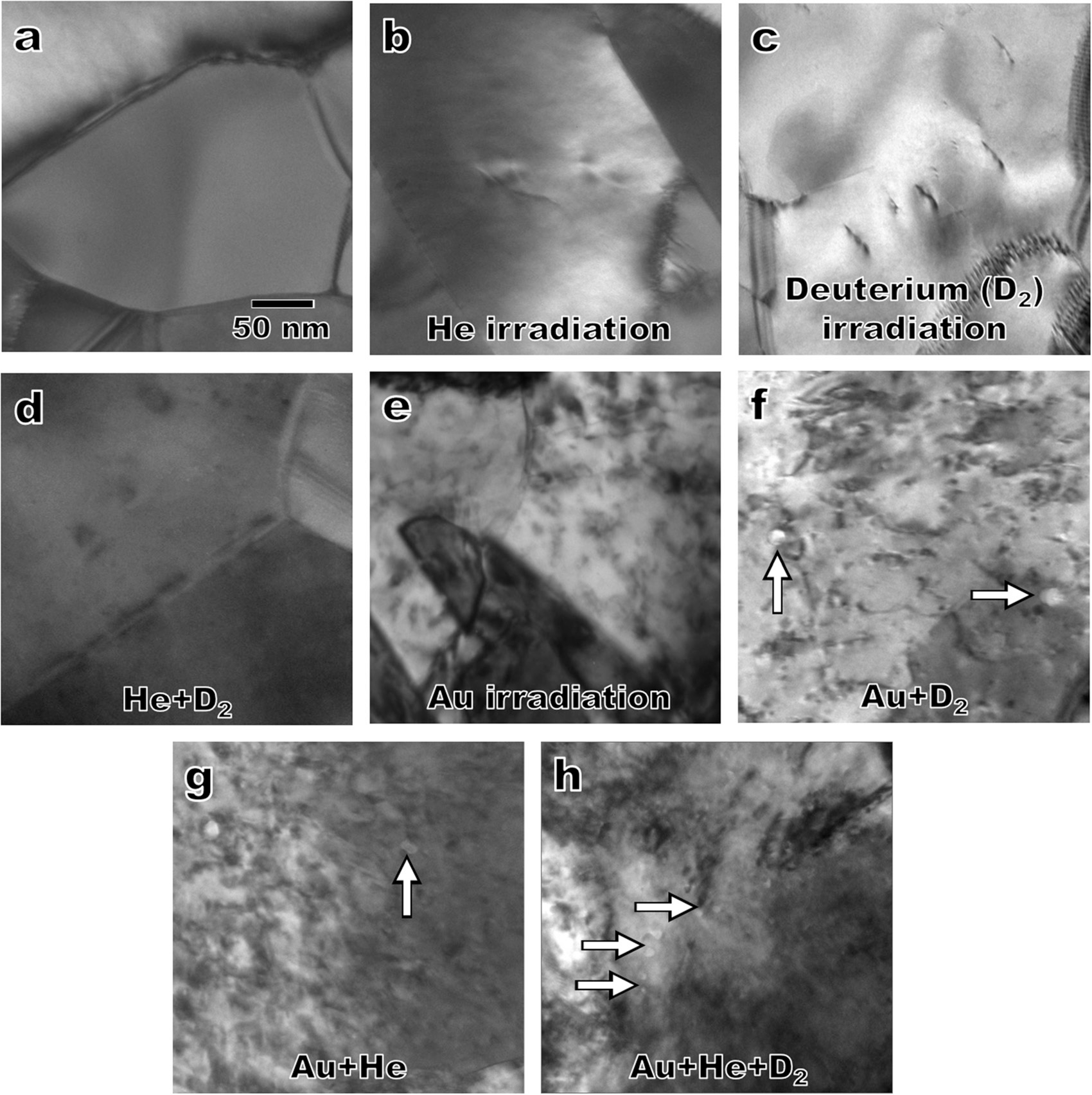
Figure 3: TEM micrographs of nanocrystalline Au shown a) before irradiation and after irradiation with b) He, c) deuterium (D2), d) combined He and D2, e) Au, f) Au and D2, g) Au and He, and h) triple-beam Au, He, and D2. White arrows indicate the presence of gas-filled cavities. The micrograph magnification is constant for all images.
Combining the heavy Au ion and the light gaseous species led to the synergistic formation of cavities on the order of 10 nm, highlighted by the white arrows in Figure 3f (Au ~4.2 × 10¹³ ions cm−2, D2 ~1.7 × 10¹⁵ ions cm−2) and 3g (Au ~1.5 × 10¹³ ions cm−2, He ~4.5 × 10¹⁶ ions cm−2), respectively. In some cases, these cavities have been observed to form and disappear over a period of several seconds [Reference Taylor25,Reference Chisholm30] and appear to be correlated with single Au ion strike events. The micrograph in Figure 3h illustrates the effects of irradiation with all three beams. It is highly plausible that nanoscale synergistic processes drive macroscopic phenomena such as the irradiation-induced swelling observed by Tanaka et al. in He, H, and Fe implanted in Fe-Cr alloys [Reference Tanaka31]. It should be noted that the relative fluence and flux of each species appear to play a role in the formation of cavities and that further work with both experiments and modeling is required to understand the details of this complex phenomenon.
The triple-beam irradiation experiments presented here demonstrate the real potential to elucidate synergistic effects that are only observable through these combined in-situ TEM conditions. By using engineering materials with more complex microstructures [Reference El-Atwani32,Reference El-Atwani33], it is possible to explore unique mechanistic behaviors that present themselves at grain boundaries, phase boundaries, or other regions that contribute to degradation.
Rapid in-situ heating and cooling
Materials used in applications such as deep space exploration and other extreme locations often undergo temperature swings ranging from -180°C to more than 500°C [Reference Ghidini2], which can negatively affect the long-term survivability. Conversely, rapid temperature changes can quench unique non-equilibrium structures into a material, such as SFTs [Reference Robach34] and amorphous intergranular films (AIFs) [Reference Schuler35]. These far-from-equilibrium states create unique opportunities to analyze new defects that are typically only stable on timescales of nanoseconds to microseconds.
To demonstrate the ability of the I3TEM to produce rapidly changing thermal environments, the IR laser system was combined with a Gatan Model 636.6 cryogenic TEM holder to assess thermal response in nanocrystalline Pt. Figure 4a shows an overview of the deposited Pt film cooled to -175°C, with an average grain size of 13.8 ± 3.1 nm. Intergranular cracks resulting from film deposition are visible in the high-magnification micrograph in Figure 4b. Figure 4c shows the response of the film after a one-second laser exposure over a spot size of approximately 80 µm in diameter, producing a power density of 72 kW cm−2. The high-magnification image in Figure 4d shows that significant abnormal grain growth occurs from the exposure, with average grain diameters of 54.9 ± 30.7 nm. The intergranular cracks (~7 nm long and 4 nm wide on average) have largely healed, and small intragranular cavities (~3 nm in diameter on average) have formed.
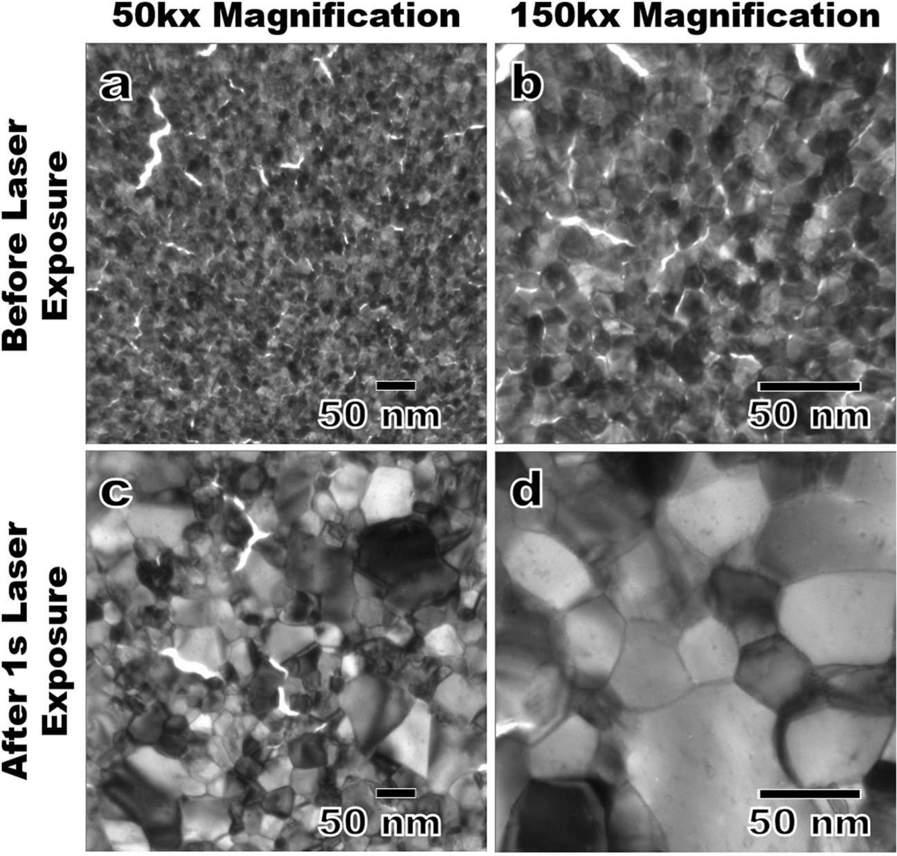
Figure 4: a) A TEM micrograph of cryogenically cooled nanocrystalline Pt films prior to laser heating, and b) a high-magnification image of the film microstructure. c) An overview of the resultant microstructure of the Pt films following a one-second IR laser heating-cryogenic cooling cycle, and d) a high-magnification micrograph of the thermally cycled Pt.
The Relativity system was implemented to observe microstructural evolution during near-instantaneous heating via sub-framing and compressive sensing. This I3TEM component has been used to observe the fast dynamics of agglomeration and sintering in Au nanoparticles and rapid grain growth in nanocrystalline Au films on time scales of 3.5 and 0.1 ms, respectively [Reference Reed18]. The addition of high-precision timing and gating systems for laser or ion irradiation pulses opens the possibilities for new discoveries of materials under highly dynamic conditions.
Combined environments in mechanical testing
To better understand the mechanical properties and degradation behavior of structural materials, it is necessary to evaluate their performance under simulated operating conditions. Combining mechanical testing with simultaneous ion irradiation [Reference Dillon36,Reference Bufford37], laser heating [Reference Grosso22], or both [Reference Dillon36] while imaging in real time provides an avenue to gain a deeper understanding of the deformation processes involved. The I3TEM enables the coupling of an ion beam for irradiation damage, an IR laser for heating over 2000°C, and the Bruker-Hysitron PI-95 TEM holder for quantitative mechanical deformation in a manner demonstrated in Figure 5a. An example study using the in-situ mechanical testing and ion irradiation capabilities to compress a 14YWT oxide dispersion-strengthened (ODS) steel pillar with a 1 µm PI-95 diamond flat punch is seen in Figure 5b. Both the irradiated and unirradiated pillars were loaded with 445 MPa of stress and held for 300 seconds at room temperature. Under irradiation with a 2.8 MeV Au beam (~2.8 × 10⁻² displacements per atom s−1), the irradiation-induced creep rate of the ODS steel increased from negligible levels to 6 × 10⁻⁴ s−1 as shown in Figure 5c. The observed creep rate is higher than what is expected of ODS steels [Reference Chen38,Reference Sagaradze39], though further analysis is underway to examine effects related to sample geometry, dose rate, and other potential contributing factors. Additional nanomechanical experiments using the full extent of the high-temperature and ion-bombardment capabilities in the I3TEM have been performed by the Dillon group from the University of Illinois [Reference Jawaharram40,Reference Jawaharram41].

Figure 5: a) A schematic demonstrating combined laser heating, ion irradiation, and mechanical testing during in-situ TEM imaging (punch diameter ≈1 µm, laser beam diameter ≈80 µm, ion beam area ≈5 mm2, pillar size ≈700 nm-tall, ≈300 nm-wide, ≈200 nm-thick, not to scale). b) TEM micrograph of a 14YWT steel pillar and PI-95 diamond punch. c) The strain rates of the irradiated and unirradiated pillars at room temperature.
While most of the in-situ mechanical testing performed in combined environments has been simple tensile or compression tests, the ability to perform far more complex geometries are possible. Fatigue testing [Reference Bufford21] and tribological wear [Reference Milne42] have recently been demonstrated in situ in the TEM and could readily be combined with simultaneous laser heating and ion irradiation to maximize the potential of the instrument.
In-situ optical spectrometry
Semiconductor materials produce photons in the visible light spectrum when exposed to many of the stimuli in the harsh environments discussed. Phenomena such as ion beam induced luminescence (IBIL), cathodoluminescence (CL), and photoluminescence (PL) are particularly useful for determining real-time property changes in a material. The spectra provide data on the chemical, structural, and electronic properties of materials during in-situ experiments, creating a complementary monitoring system for the band gap evolution.
The I3TEM has previously demonstrated the utility of IBIL from fused quartz for the simple purpose of aligning the ion beams produced by the accelerators [Reference Hattar16]. An Andor SR303iB spectrometer with a wavelength range of 190 nm to 10 µm and a resolution of 0.1 nm has been integrated into the optical path of the TEM ion beam line. Despite the low collection angle of this optical path, PL produced by the 1064 nm laser, CL created by 80–200 kV electrons, and IBIL from a range of ion species and energies is achievable. For example, the P47 particle (Ce-doped YAG) circled in Figure 6a was exposed to the 200 kV electron beam for a total of five minutes, generating the example spectra shown in Figure 6b. The CL spectrum is discernable above the background, clearly demonstrating the ability to generate useful spectra for chemical and structural analysis. While the overall signal is weaker than those typically collected from a dedicated CL microscope, these measurements provide yet another unique capability for advanced in-situ characterization.
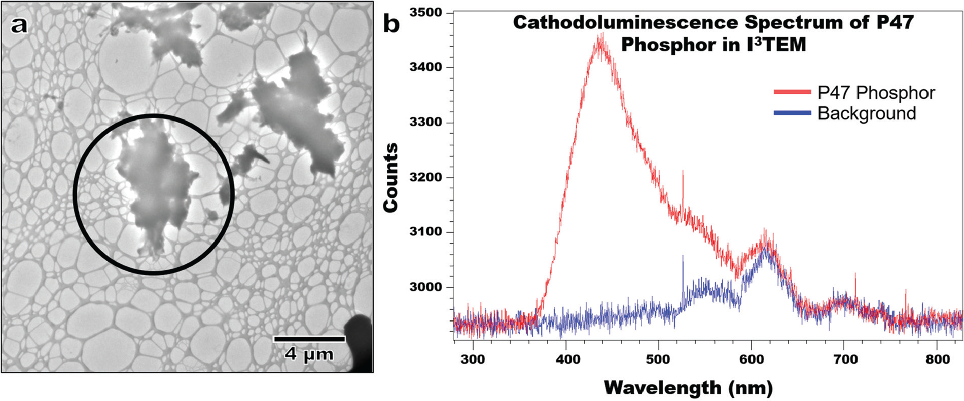
Figure 6: a) TEM micrograph of a P47 phosphor particle used to demonstrate cathodoluminescence (CL) and b) the collected spectrum.
Discussion
Future I3TEM enhancements
While the I3TEM is a versatile and one-of-a-kind microscope, it is far from complete as an instrument to perform in-situ experiments in combined extreme environments. To enhance the existing ion irradiation facilities, an additional upstream bending magnet with a 1 Tesla field is being added to the TEM beamline. This will improve the steering and focusing of ion beams up to and including 100 MeV Au for high-energy thermal spike experiments. Plans to incorporate a UV-visible light source for photonics experiments, a gas injection system to perform pseudo environmental TEM (ETEM) experiments, and a Raman spectroscopy setup for real-time monitoring of chemistry, temperature, and strain are also currently under consideration.
Future potential for coupled extreme environments
In order to meet the needs of future extreme materials research, several key areas of improvement have been identified for the in-situ TEM community [Reference Taheri5,Reference Robertson43]. Challenges related to capturing phenomena at nanosecond timescales in nanometer-length scales are of utmost importance to fully understand the coupled extreme environments discussed [Reference Zewail44,Reference Kulovits45] with ongoing work focusing on the reliability and accessibility of such experiments. Real-time monitoring of electron beam effects and precise temperatures of materials in the experiments are also crucial for providing accurate inputs for computational models built from the data [Reference Pazdernik46]. Given the progress of artificial intelligence and machine learning for materials science applications [Reference Butler47], it is well within grasp to have the tools necessary to synthesize rich datasets generated from these complex environments into well-understood mechanistic behaviors. In-situ microscopy has clearly demonstrated its worth in the realm of fundamental materials studies. As a result, it has experienced tremendous growth and continues to push the boundaries of coupled extreme environments within an electron microscope.
Conclusion
The need to understand fundamental material responses to complex settings has continuously driven the growth of in-situ microscopy. A snapshot of the current diversity of experiments that are possible to explore coupled extreme environments at the I3TEM facility has been demonstrated. Through ion beam irradiation, thermal cycling, mechanical testing, and real-time optical spectroscopy, the present and future potential of in-situ microscopy was highlighted.
Acknowledgements
The authors would like to thank Drs. Bryan Reed, Sang Tae Park, Ruth S. Bloom, and Daniel Masiel from IDES/JEOL for their assistance, as well as Dr. Patrick Price, Dr. Anthony Monterossa, and Mr. Michael Marshall of SNL. R.J.P., D.C.B., B.L.B., and K.H. were fully supported by the DOE Office of Basic Energy Science, Materials Science and Engineering Division. The 14YWT ODS work was supported by the U.S. Department of Energy, Office of Nuclear Energy under DOE Idaho Operations Office Contract DE-AC07- 051D14517 as part of a Nuclear Science User Facilities experiment. This work was performed, in part, at the Center for Integrated Nanotechnologies, an Office of Science User Facility operated for the U.S. Department of Energy (DOE) Office of Science. Sandia National Laboratories is a multimission laboratory managed and operated by National Technology & Engineering Solutions of Sandia, LLC, a wholly owned subsidiary of Honeywell International Inc., for the U.S. Department of Energy's National Nuclear Security Administration under contract DE-NA0003525.


