1 Introduction
Transmitted volume Bragg gratings (TBGs) recorded in photothermorefractive (PTR) glass have been widely developed in near-field angular filtering technology due to the high diffraction efficiency, excellent angular selectivity and high damage threshold[Reference Glebov1]. The beam quality of laser beams in both near and far fields can be improved[Reference Zhang, Yuan, Wu, Feng, Zou and Zhang2, Reference Gao, Zhang, Sun and Yuan3]. For a high-power laser system, such as National Ignition Fusion (NIF) and Laser MegaJoule (LMJ), since the highly coherent laser pulse with high spectral power density may induce transverse stimulated Brillouin scattering (TSBS)[Reference Murray, Smith, Ehrlich, Kyrazis, Thompson, Weiland and Wilcox4], sinusoidal phase modulation, known as frequency modulation (FM), is often used to broaden the bandwidth of laser pulses, suppress the TSBS and improve uniformity of the focal spot[Reference Zhang, Zhou, Jiang, Li, Feng and Lin5]. In such laser systems, any inhomogeneous change of the spectrum, probably resulting from dispersion, gain narrowing, Fabry–Perot etalon effects in optical elements, and so on, will cause amplitude modulation (AM) in the pulse[Reference Hocquet, Penninckx, Bordenave, Gouedard and Jaouen6]. Without control, this amplitude-modulated pulse may damage the optical elements[Reference Lindl, Amedt, Berger, Glendinning, Glenzer, Hann, Landen and Suter7]. Currently, FM-to-AM conversion resulting from the amplifier media, spatial filters, fiber components and triple-frequency operation, etc.[Reference Hocquet, Penninckx, Bordenave, Gouedard and Jaouen6, Reference Yang, Feng, Han, Zheng, Li and Tan8], has been studied at the NIF and LMJ. As the key element in angular filtering, the TBGs not only have excellent angular selectivity but also spectral selectivity. Some AM will be introduced in the diffracted pulse, which may be a risk to system integrity. Therefore, obtaining a wide spectral selectivity of TBGs with good angular selectivity may be a key problem in suppressing FM-to-AM conversion, which is useful for the application of TBGs in such high-power laser systems. In previous work on TBGs, the laser beams used were restricted to CW lasers. Also, spectral selectivity and FM-to-AM conversion caused by angular filtering in high-power laser systems have not been discussed.
In this paper, the FM-to-AM conversion introduced by TBGs is discussed on the basis of the coupled-wave theory and Fourier optics. According to the dependence of grating structural parameters on the Bragg selectivity, wide spectral selectivity and good angular selectivity can be obtained by controlling the grating period and thickness, which can effectively suppress FM-to-AM conversion. Finally, FM-to-AM conversion caused by three TBGs with different spectral selectivities is demonstrated in the ‘Shenguang’ facility.

Figure 1. Frequency spectrum filtered by the TBGs and the FM-to-AM conversion: (a) and (b) TBG-1, (c) and (d) TBG-2, (e) and (f) TBG-3, (g) and (h) TBG-4.

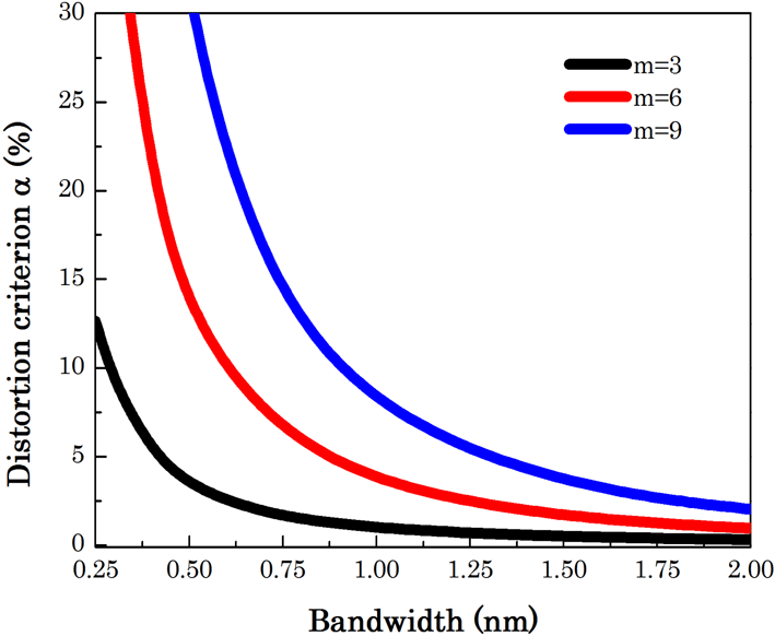
Figure 2. Dependence of the distortion criterion on the bandwidth.

Figure 3. Dependence of the Bragg selectivity on the grating period and thickness: (a)
![]() $\unicode[STIX]{x1D706}_{0}=1053$
nm,
$\unicode[STIX]{x1D706}_{0}=1053$
nm,
![]() $d=2.5$
mm,
$d=2.5$
mm,
![]() $\unicode[STIX]{x1D719}=90^{\circ }$
; (b)
$\unicode[STIX]{x1D719}=90^{\circ }$
; (b)
![]() $\unicode[STIX]{x1D706}_{0}=1053$
nm,
$\unicode[STIX]{x1D706}_{0}=1053$
nm,
![]() $\unicode[STIX]{x1D6EC}=1.5~\unicode[STIX]{x03BC}\text{m}$
,
$\unicode[STIX]{x1D6EC}=1.5~\unicode[STIX]{x03BC}\text{m}$
,
![]() $\unicode[STIX]{x1D719}=90^{\circ }$
.
$\unicode[STIX]{x1D719}=90^{\circ }$
.

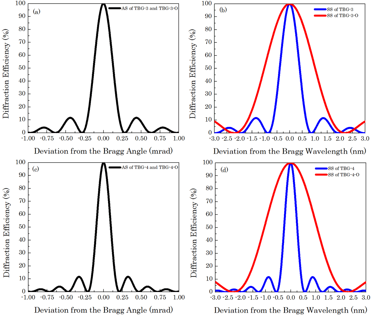
Figure 4. Bragg selectivity for TBG-3, TBG-3-O, TBG-4 and TBG-4-O.
2 Principle of FM-to-AM conversion for angular filter
The optical field for a laser pulse with sinusoidal phase modulation can be written as[Reference Hocquet, Penninckx, Bordenave, Gouedard and Jaouen6]
where
![]() $m$
is the modulation coefficient and
$m$
is the modulation coefficient and
![]() $f_{m}$
is the modulation frequency. The corresponding frequency spectrum of the laser pulse can be obtained from the Fourier transform of Equation (1):
$f_{m}$
is the modulation frequency. The corresponding frequency spectrum of the laser pulse can be obtained from the Fourier transform of Equation (1):
where
![]() $J_{n}$
(
$J_{n}$
(
![]() $m$
) is the
$m$
) is the
![]() $n$
th-order Bessel function[Reference Boyd9]. In theory, the spectrum bandwidth is infinite. However, the 98% energy of the frequency spectrum is centralized in the range of
$n$
th-order Bessel function[Reference Boyd9]. In theory, the spectrum bandwidth is infinite. However, the 98% energy of the frequency spectrum is centralized in the range of
![]() $2(m+1)f_{m}$
due to Carson’s rule[Reference Carson10]. According to the coupled-wave theory[Reference Kogelnik11], the Bragg selectivity of the lossless TBGs, including angular selectivity (AS) and spectral selectivity (SS), can be described as
$2(m+1)f_{m}$
due to Carson’s rule[Reference Carson10]. According to the coupled-wave theory[Reference Kogelnik11], the Bragg selectivity of the lossless TBGs, including angular selectivity (AS) and spectral selectivity (SS), can be described as
where
![]() $S$
is the complex amplitude of the output signal for a reference incident wave with unit amplitude and equals
$S$
is the complex amplitude of the output signal for a reference incident wave with unit amplitude and equals
![]() $\unicode[STIX]{x0394}n$
is the refractive index modulation,
$\unicode[STIX]{x0394}n$
is the refractive index modulation,
![]() $n_{\text{0}}$
is the average refractive index of the grating material,
$n_{\text{0}}$
is the average refractive index of the grating material,
![]() $d$
is the grating thickness,
$d$
is the grating thickness,
![]() $\unicode[STIX]{x1D6EC}$
is the grating period,
$\unicode[STIX]{x1D6EC}$
is the grating period,
![]() $\unicode[STIX]{x1D703}_{r}$
and
$\unicode[STIX]{x1D703}_{r}$
and
![]() $\unicode[STIX]{x1D703}_{s}$
are the angles of the incident and diffracted beams, respectively, and
$\unicode[STIX]{x1D703}_{s}$
are the angles of the incident and diffracted beams, respectively, and
![]() $\unicode[STIX]{x1D706}$
is the wavelength of the incident beam.
$\unicode[STIX]{x1D706}$
is the wavelength of the incident beam.
![]() $\unicode[STIX]{x0394}\unicode[STIX]{x1D703}$
and
$\unicode[STIX]{x0394}\unicode[STIX]{x1D703}$
and
![]() $\unicode[STIX]{x0394}\unicode[STIX]{x1D706}$
are the deviations from the Bragg angle and Bragg wavelength, respectively. Thus, the diffracted frequency spectrum can be given as
$\unicode[STIX]{x0394}\unicode[STIX]{x1D706}$
are the deviations from the Bragg angle and Bragg wavelength, respectively. Thus, the diffracted frequency spectrum can be given as
The optical field and the intensity distribution of the laser pulse can be obtained from the inverse Fourier transform of Equation (7):

Figure 5. Frequency spectrum filtered by optimized TBGs and the FM-to-AM conversion: (a) and (b) TBG-3-O, (c) and (d) TBG-4-O.

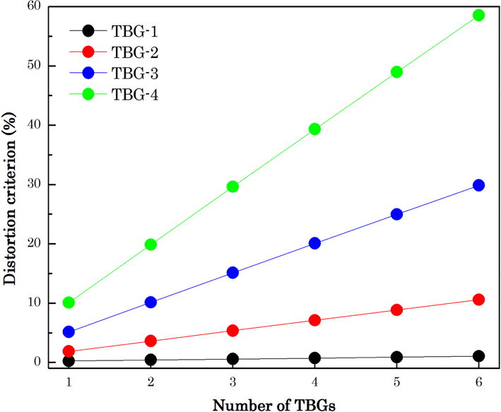
Figure 6. Dependence of the distortion criterion on the number of TBGs.
The distortion criterion
![]() $\unicode[STIX]{x1D6FC}$
, used to evaluate the strength of the FM-to-AM conversion[Reference Wedding12], is defined as
$\unicode[STIX]{x1D6FC}$
, used to evaluate the strength of the FM-to-AM conversion[Reference Wedding12], is defined as
where
![]() $I_{\max }$
and
$I_{\max }$
and
![]() $I_{\min }$
are the maximum and minimum intensity for more than one modulated period, respectively.
$I_{\min }$
are the maximum and minimum intensity for more than one modulated period, respectively.
![]() $\unicode[STIX]{x1D6FC}$
ranges from 0 to 200% and is ideally equal to 0.
$\unicode[STIX]{x1D6FC}$
ranges from 0 to 200% and is ideally equal to 0.
In current high-power laser facilities, uniformity of the laser beam is usually improved by the traditional pinhole spatial filter. The cutoff frequency of the pinhole spatial filter is set as dozens of times the diffraction limit of the laser beam, which equals
![]() $1.22\unicode[STIX]{x1D706}/D$
, and is related to the beam size
$1.22\unicode[STIX]{x1D706}/D$
, and is related to the beam size
![]() $D$
. As the new-type angular filter, TBGs are expected to match up with the pinhole spatial filter to further improve the beam quality. However, TBGs are expected to be used in the preamplifier system, limited by the current preparation technology. The preamplifier system has two stages with different beam sizes. In the simulation, four sinusoidally phase-modulated beams with a central wavelength of 1053 nm are filtered by four different TBGs, respectively. The sizes of the four beams are set to
$D$
. As the new-type angular filter, TBGs are expected to match up with the pinhole spatial filter to further improve the beam quality. However, TBGs are expected to be used in the preamplifier system, limited by the current preparation technology. The preamplifier system has two stages with different beam sizes. In the simulation, four sinusoidally phase-modulated beams with a central wavelength of 1053 nm are filtered by four different TBGs, respectively. The sizes of the four beams are set to
![]() $10~\text{mm}\times 10~\text{mm}$
,
$10~\text{mm}\times 10~\text{mm}$
,
![]() $20~\text{mm}\times 20~\text{mm}$
,
$20~\text{mm}\times 20~\text{mm}$
,
![]() $30~\text{mm}\times 30~\text{mm}$
,
$30~\text{mm}\times 30~\text{mm}$
,
![]() $40~\text{mm}\times 40~\text{mm}$
, respectively. The structural parameters of the TBGs are shown in Table 1. The cutoff frequency is defined as the half-width at the first zero point (HWFZ) of the AS curve and set to about ten times the diffraction limit.
$40~\text{mm}\times 40~\text{mm}$
, respectively. The structural parameters of the TBGs are shown in Table 1. The cutoff frequency is defined as the half-width at the first zero point (HWFZ) of the AS curve and set to about ten times the diffraction limit.
The bandwidth is defined as the half-width at the first zero point of the SS curve. The bandwidths of the four TBGs are 4.50 nm, 1.35 nm, 0.87 nm and 0.60 nm, respectively. The greater the spectral filtering of the TBGs, the stronger the FM-to-AM conversion. The diffraction efficiencies (DE) of the four TBGs are all 100%. The red and blue lines in Figures 1(a), 1(c), 1(e), and 1(g) represent the SS of TBGs and spectral power density of the incident laser pulse with a pulse duration of 3 ns, a modulation coefficient
![]() $m$
of 6 and a modulation frequency
$m$
of 6 and a modulation frequency
![]() $f_{m}$
of 3.3 GHz. On the basis of the calculated results, the distortion criterion
$f_{m}$
of 3.3 GHz. On the basis of the calculated results, the distortion criterion
![]() $\unicode[STIX]{x1D6FC}$
of the diffracted pulse after TBG-3 and TBG-4 has values of 5.14% and 10.08%, respectively, which may affect safe operation of the laser system.
$\unicode[STIX]{x1D6FC}$
of the diffracted pulse after TBG-3 and TBG-4 has values of 5.14% and 10.08%, respectively, which may affect safe operation of the laser system.

Figure 7. Schematic diagram demonstrating FM-to-AM conversion on TBGs.

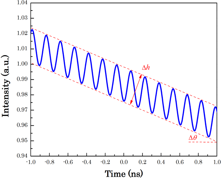
Figure 8. Fluctuation of the inclined laser pulse.
Figure 2 shows the dependence of the distortion criterion on the bandwidth. In an actual high-power laser facility, assessment of FM-to-AM conversion should consider all the optical components, not just the TBGs. The distortion criterion
![]() $\unicode[STIX]{x1D6FC}$
accumulated by all the optical components should be controlled to less than 5%[Reference Hocquet, Lacroix and Penninckx13] to ensure safe operation of the laser facility. In general, the requirement of the distortion criterion
$\unicode[STIX]{x1D6FC}$
accumulated by all the optical components should be controlled to less than 5%[Reference Hocquet, Lacroix and Penninckx13] to ensure safe operation of the laser facility. In general, the requirement of the distortion criterion
![]() $\unicode[STIX]{x1D6FC}$
for TBGs can be estimated from the difference between 5% and the actual distortion criterion
$\unicode[STIX]{x1D6FC}$
for TBGs can be estimated from the difference between 5% and the actual distortion criterion
![]() $\unicode[STIX]{x1D6FC}$
accumulated by all the optical components without the TBGs.
$\unicode[STIX]{x1D6FC}$
accumulated by all the optical components without the TBGs.
According to the coupled-wave theory, effective optimization of the TBGs’ structural parameters may make it possible to increase the SS while leaving the AS unchanged. It can ensure effective angular filtering and lower FM-to-AM conversion. The cutoff frequency and bandwidth of TBGs can be written as
The cutoff frequency and bandwidth are almost proportional to
![]() $\unicode[STIX]{x1D6EC}$
and
$\unicode[STIX]{x1D6EC}$
and
![]() $\unicode[STIX]{x1D6EC}^{\text{2}}$
, respectively, which means the SS has a faster growth rate than the AS when the grating period increases, as shown in Figure 3(a). On the other hand, the AS and SS are both inversely proportional to
$\unicode[STIX]{x1D6EC}^{\text{2}}$
, respectively, which means the SS has a faster growth rate than the AS when the grating period increases, as shown in Figure 3(a). On the other hand, the AS and SS are both inversely proportional to
![]() $d$
, which means they almost have the same rate of decrease when the thickness increases, as shown in Figure 3(b). Therefore, it is possible to obtain a larger bandwidth and a good cutoff frequency by enlarging the grating period and thickness simultaneously. The optimized structural parameters of TBG-3 and TBG-4 are shown in Table 2.
$d$
, which means they almost have the same rate of decrease when the thickness increases, as shown in Figure 3(b). Therefore, it is possible to obtain a larger bandwidth and a good cutoff frequency by enlarging the grating period and thickness simultaneously. The optimized structural parameters of TBG-3 and TBG-4 are shown in Table 2.

Figure 9. Frequency spectra filtered by TBGs and temporal profiles of the laser pulses: (a) and (b) TBG-I, (c) and (d) TBG-II, (e) and (f) TBG-III.
Figure 4 shows the change in AS and SS before and after optimization of the structural parameters. For TBG-3 and TBG-4, the angular selectivities before and after the structural parameters’ optimization are the same and the cutoff frequencies are still equal to 0.28 mrad and 0.21 mrad, respectively. The bandwidths increase from 0.87 nm to 2.20 nm for TBG-3 and from 0.60 nm to 2.28 nm for TBG-4. As shown in Figure 5, the filtered frequency spectrum reduces significantly after optimizing the grating structural parameters. The distortion criterion
![]() $\unicode[STIX]{x1D6FC}$
reduces from 5.14% and 10.08% to 0.76% and 0.72%, respectively, which means that FM-to-AM conversion in the high-power laser system can be suppressed.
$\unicode[STIX]{x1D6FC}$
reduces from 5.14% and 10.08% to 0.76% and 0.72%, respectively, which means that FM-to-AM conversion in the high-power laser system can be suppressed.
Pairs of the two orthogonal TBGs are needed to realize a two-dimensional angular filter in the laser facility. The combination of more TBGs with the same spectral selectivity will cause a further inhomogeneous change of the laser pulse. Amplitude modulation in the pulse will be enhanced. The distortion criterion increases linearly with an increase in the number of TBGs, as shown in Figure 6.
In actual high-power laser facilities, TBGs are often inserted in the optical path of the latter amplification. The former inhomogeneous change of spectrum, probably resulting from dispersion, gain narrowing or gain saturation effects, will cause some FM-to-AM conversion. The FM-to-AM conversion resulting from the TBGs is cumulative. However, the former inhomogeneous change of spectrum does not increase the bandwidth of the laser beam with sinusoidal phase modulation. Therefore, the effective optimization of the TBGs’ structural parameters still applies.
3 Demonstration of FM-to-AM conversion for TBGs
A schematic diagram demonstrating FM-to-AM conversion with TBGs is shown in Figure 6. The laser beam used in the experiment was sinusoidally phase-modulated in the ‘Shenguang’ facility with a wavelength of 1053 nm, a pulse duration of 3 ns, a modulation index
![]() $m$
of 12 and a modulation frequency
$m$
of 12 and a modulation frequency
![]() $f_{m}$
of 2.488 GHz. Then, a collimated laser beam with a size of
$f_{m}$
of 2.488 GHz. Then, a collimated laser beam with a size of
![]() $10~\text{mm}\times 10~\text{mm}$
was obtained by the
$10~\text{mm}\times 10~\text{mm}$
was obtained by the
![]() $4f$
system and diffracted through the TBGs recorded in PTR glass. A photoelectric detector and an oscilloscope were used to collect the temporal profile of the original pulse and the diffracted pulse. The structural parameters of the TBGs are shown in Table 3.
$4f$
system and diffracted through the TBGs recorded in PTR glass. A photoelectric detector and an oscilloscope were used to collect the temporal profile of the original pulse and the diffracted pulse. The structural parameters of the TBGs are shown in Table 3.
In general, the distortion criterion
![]() $\unicode[STIX]{x1D6FC}$
is used to evaluate the FM-to-AM conversion for the flat-topped pulse. However, the temporal profile of the pulse in the real laser system was inclined due to the gain recovery effect. In this case, the quantity
$\unicode[STIX]{x1D6FC}$
is used to evaluate the FM-to-AM conversion for the flat-topped pulse. However, the temporal profile of the pulse in the real laser system was inclined due to the gain recovery effect. In this case, the quantity
![]() $\unicode[STIX]{x0394}h$
can be used to describe the fluctuation of the pulse, which equals the distance between the envelopes of the inclined pulse, as shown in Figure 7. Also the distortion criterion
$\unicode[STIX]{x0394}h$
can be used to describe the fluctuation of the pulse, which equals the distance between the envelopes of the inclined pulse, as shown in Figure 7. Also the distortion criterion
![]() $\unicode[STIX]{x1D6FC}$
could be revised as
$\unicode[STIX]{x1D6FC}$
could be revised as
where
![]() $y_{\text{0}}$
equals the average intensity of the pulse.
$y_{\text{0}}$
equals the average intensity of the pulse.
The red and blue lines in Figures 8(a), 8(c), and 8(e) represent the calculated SS of TBGs and the spectral power density of the incident laser pulse in the experiment, respectively. The bandwidth of the incident laser pulse was about 0.3 nm. The black, blue and red lines in Figures 8(b), 8(d), and 8(f) represent temporal profiles of the incident laser pulse, the diffracted laser pulse in the experiment and the diffracted laser pulse in theory, respectively. TBG-III has the narrowest SS and most spectral components were filtered. The distortion criterion
![]() $\unicode[STIX]{x1D6FC}$
before and after TBGs is shown in Table 4. The original
$\unicode[STIX]{x1D6FC}$
before and after TBGs is shown in Table 4. The original
![]() $\unicode[STIX]{x1D6FC}$
of the incident pulse is 12.8%. After diffraction by three TBGs,
$\unicode[STIX]{x1D6FC}$
of the incident pulse is 12.8%. After diffraction by three TBGs,
![]() $\unicode[STIX]{x1D6FC}$
rose to 13.6%, 28.4% and 42.5%. The
$\unicode[STIX]{x1D6FC}$
rose to 13.6%, 28.4% and 42.5%. The
![]() $\unicode[STIX]{x0394}\unicode[STIX]{x1D6FC}$
of TBG-II and TBG-III was about 19.5 times and 37.1 times larger than that after TBG-I, respectively. The results are in good agreement with the theoretical ones.
$\unicode[STIX]{x0394}\unicode[STIX]{x1D6FC}$
of TBG-II and TBG-III was about 19.5 times and 37.1 times larger than that after TBG-I, respectively. The results are in good agreement with the theoretical ones.
Table 1. Structural parameters of TBGs.

Table 2. Optimized structural parameters of TBG-3 and TBG-4.

4 Conclusions
In summary, the FM-to-AM conversion caused by TBGs with different spectral selectivities is studied and demonstrated in the ‘Shenguang’ facility. TBGs with narrower spectral selectivity will lead to stronger FM-to-AM conversion. Wide spectral selectivity and good angular selectivity of TBGs can be obtained by controlling the grating period and thickness simultaneously. Then the distortion criterion can be reduced to less than 5%, and the FM-to-AM conversion can be effectively suppressed. Experimental results show that the distortion criterion
![]() $\unicode[STIX]{x1D6FC}$
of the filtered pulses after the TBGs rose to 13.6%, 28.4% and 42.5%. The values of
$\unicode[STIX]{x1D6FC}$
of the filtered pulses after the TBGs rose to 13.6%, 28.4% and 42.5%. The values of
![]() $\unicode[STIX]{x0394}\unicode[STIX]{x1D6FC}$
after the TBGs with spectral selectivities of 1.0 nm and 0.75 nm were about 19.5 times and 37.1 times larger, respectively, than that after the TBG with a spectral selectivity of 8.7 nm. Experimental results are in good agreement with the theoretical ones. The above work will provide some valuable guidance for angular filters based on TBGs for application in high-power laser systems.
$\unicode[STIX]{x0394}\unicode[STIX]{x1D6FC}$
after the TBGs with spectral selectivities of 1.0 nm and 0.75 nm were about 19.5 times and 37.1 times larger, respectively, than that after the TBG with a spectral selectivity of 8.7 nm. Experimental results are in good agreement with the theoretical ones. The above work will provide some valuable guidance for angular filters based on TBGs for application in high-power laser systems.
Table 3. Structural parameters of the TBGs in the experiment.

Table 4. Results of the distortion criterion
![]() $\unicode[STIX]{x1D6FC}$
.
$\unicode[STIX]{x1D6FC}$
.

Acknowledgements
This work is supported by the National Key R&D Program of China (No. 2016YFF0100903), National Natural Science Foundation of China (NSFC) (Nos. 61775153, 61705153, and 11504255), and Priority Academic Program Development of Jiangsu Higher Education Institutions (PAPD).


