1 Introduction
In recent years, low-repetition-rate ultrafast fiber lasers have found applications in a diverse range of areas, such as free-space optical communications, time–frequency transfer, biomedical surgery and unambiguous long-distance ranging[Reference McCarthy, Krichel, Gemmell, Ren, Tanner, Dorenbos, Zwiller, Hadfield and Buller1–Reference Du, Pang, Wu, Li, Peng, Tao, Wu and Wu5]. In these areas, Er-doped fiber lasers (EDFLs) are preferred by virtue of their eye safety, low atmospheric attenuation, and reduced solar background noise. To generate low-repetition-rate, stable lasers, a commonly used way is to combine a pulse picker, such as acousto-optical modulator (AOM) or electro-optic modulator (EOM), with a mode-locked EDFL[Reference Sobon, Kaczmarek, Gluszek, Sotor and Abramski6, Reference Peng, Kim, Mielke, Jennings, Masor, Stohl, Chavez-Pirson, Nguyen, Rhonehouse, Zong, Churin and Peyghambarian7]. Assuming that the laser outputs a certain average power, the lower repetition rate of the laser, the higher energy of the output pulses. However, in such a laser system, high performance is required for the pulse picker, such as an excellent on–off ratio, a short response time, accurate synchronization and low insertion loss. Furthermore, to drive the pulse picker, a range of electrical designs is necessary, making the system complicated.
Alternatively, simply extending the fiber length can also decrease the pulse repetition rate[Reference Chen, Zhang, Zhou, Cai, Ren and Zhang8–Reference Ibarra-Escamilla, Pottiez, Kuzin, Grajales-Couti O and Haus10]. However, long-cavity fiber lasers are inherently unstable due to mechanical perturbations and temperature variations, unless polarization-maintaining fibers (PMFs) are employed[Reference Shen, Li and Zeng11]. The usage of PMFs excludes nonlinear polarization evolution (NPE), a well-known mode-locking technique employed in the laser, as NPE is based on single-mode fibers. Since low-repetition-rate ultrafast fiber lasers generally possess high energy, saturable absorbers can be easily damaged in this case. A solution to mode-lock long-cavity fiber lasers based on PMFs is using the nonlinear amplifying loop mirror (NALM) technique[Reference Fermann, Haberl, Hofer and Hochreiter12]. Indeed, NALM has been demonstrated to be capable of generating high-quality pulses with outstanding robustness and reliability. Nevertheless, conventional NALM-based lasers usually require careful design for self-starting ability, such as inserting a pulse amplitude modulator[Reference Nicholson and Andrejco13], using excessive pumping power and managing the cavity dispersion[Reference Hao, Chen, Yang, Zhu, Zhang and Zeng14]. Recently, a phase shifter has been introduced to improve the starting performance of NALM-based fiber lasers[Reference Kuse, Jiang, Lee, Schibli and Fermann15, Reference Chen, Hao and Zeng16]. However, the repetition rates of these lasers are several tens of megahertz. Such techniques have not been employed in low-repetition-rate ultrafast fiber lasers.
In low-repetition-rate laser oscillators assisted by lengthening the intracavity fiber with a large normal dispersion, the dissipative soliton (DS) has been extensively investigated. For example, Liu et al. demonstrated wave-breaking-free DS pulses at a fundamental repetition rate of less than 10 MHz, and the pulses could be further boosted to a 200-nJ energy within a 56-ps duration[Reference Liu17, Reference Wang, Liu, Gong, Mao and Feng18]. Also, in the anomalous dispersion regime, long-cavity soliton lasers have been demonstrated to generate solitons with several picoseconds duration. Soliton pulses have been achieved in an all-polarization-maintaining fiber oscillator mode-locked by a single-wall-carbon-nanotube polyimide film, delivering a 6.20-ps duration with an as low as 132-kHz repetition rate[Reference Nyushkov, Ivanenko, Kobtsev, Turitsyn, Mou, Zhang, Denisov and Pivtsov19]. However, the pronounced amplified spontaneous emission (ASE) components are a common issue both in DS and soliton lasers with low repetition rates, for the low duty cycle of pulses[Reference Nyushkov, Ivanenko, Kobtsev, Turitsyn, Mou, Zhang, Denisov and Pivtsov19, Reference Senoo, Nishizawa, Sakakibara, Sumimura, Itoga, Kataura and Itoh20]. In their experiments, ASE components arise as the pulse repetition rate becomes lower, even though the pulse interval is shorter than the lifetime of the
![]() $\text{Er}^{3+}$
ion.
$\text{Er}^{3+}$
ion.
In this work, we solve these issues in low-repetition-rate ultrafast fiber lasers by using a phase-biased NALM and a selected filter to generate pulses at a 1.84-MHz repetition rate with suppressed ASE and Kelly sidebands. A numerical simulation is first carried out to guide the experiment on pulse build-up and Kelly sideband suppression. Experimentally, a self-started NALM mode-locked Er-fiber laser is achieved with as low as 70-mW pumping power, delivering soliton pulses with a 17-pJ energy. The lowest pump power maintaining mode-locking is 24 mW. Finally, a cascaded fiber amplifier provides a total gain of 50 dB, boosting the pulse energy to
![]() $1.5~\unicode[STIX]{x03BC}\text{J}$
, which might be used in the measurement of ultrafast dynamic parameters[Reference Edwards, MacKinnon, Zweiback, Shigemori, Ryutov, Rubenchik, Keilty, Liang, Remington and Ditmire21].
$1.5~\unicode[STIX]{x03BC}\text{J}$
, which might be used in the measurement of ultrafast dynamic parameters[Reference Edwards, MacKinnon, Zweiback, Shigemori, Ryutov, Rubenchik, Keilty, Liang, Remington and Ditmire21].
2 Numerical simulation
Table 1. Schematic configuration of the simulated laser oscillator and the related parameters.

First, we numerically build the long-cavity laser oscillator with suppressed sidebands by incorporating an intracavity bandpass filter. Commercially available software which solves the extended nonlinear Schrödinger equation by the split–step Fourier transform method is used[Reference Schreiber, Ortac, Limpert and Tunnermann22]. As shown in the upper part of Table 1, the laser oscillator is built in a standing-wave cavity, including a segment of gain fiber, a segment of PM 1550 fiber, a fast saturable absorber (SA), a bandpass filter and an output coupler. Details of each element are oriented towards the experimental conditions, as listed in the lower part of Table 1. The gain fiber is Er-doped fiber with a 2-m length. Its group velocity dispersion (GVD) and third-order dispersion (TOD) are
![]() $30.2~\text{ps}^{2}/\text{km}$
and
$30.2~\text{ps}^{2}/\text{km}$
and
![]() $0.021~\text{ps}^{3}/\text{km}$
, respectively. The gain profile is assumed to have a Gaussian shape with a central wavelength of 1550 nm and a full-width at half-maximum (FWHM) of 40 nm. The PM 1550 fiber with 50-m length is used to extend the cavity length. The SA is a typical fast saturable absorber with an NALM mechanism, which has a saturable reflection of 70%, an unsaturable reflection of 30%, and a saturation power of 1 kW. The bandpass filter is designed with a rectangular transmission profile centered at 1550 nm and employed to manage the phase contribution induced by dispersion and nonlinearity in the low-repetition-rate laser cavity. The splitting ratio of the output coupler is 20%. The lengths of the SA, bandpass filter and output coupler are regarded as their fiber pigtails. The laser oscillator has a total fiber length of 55 m, corresponding to a repetition rate of 1.88 MHz and a net cavity dispersion of
$0.021~\text{ps}^{3}/\text{km}$
, respectively. The gain profile is assumed to have a Gaussian shape with a central wavelength of 1550 nm and a full-width at half-maximum (FWHM) of 40 nm. The PM 1550 fiber with 50-m length is used to extend the cavity length. The SA is a typical fast saturable absorber with an NALM mechanism, which has a saturable reflection of 70%, an unsaturable reflection of 30%, and a saturation power of 1 kW. The bandpass filter is designed with a rectangular transmission profile centered at 1550 nm and employed to manage the phase contribution induced by dispersion and nonlinearity in the low-repetition-rate laser cavity. The splitting ratio of the output coupler is 20%. The lengths of the SA, bandpass filter and output coupler are regarded as their fiber pigtails. The laser oscillator has a total fiber length of 55 m, corresponding to a repetition rate of 1.88 MHz and a net cavity dispersion of
![]() $-2.29~\text{ps}^{2}$
.
$-2.29~\text{ps}^{2}$
.
Starting from quantum noise, the long-cavity laser oscillator reaches steady state after 300 round trips when the bandpass filter is absent (Figures 1(a) and 1(b)). In the 600th round trip, the output pulse has a transform-limited temporal duration of 2.64 ps and a spectral FWHM of 1.26 nm, corresponding to a time–bandwidth product (TBP) of 0.415 (Figures 1(c) and 1(d)). Notable Kelly sidebands emerge at both sides of the central wavelength of 1549.6 nm, and the biased spectral separations are 2.8, 4.0 and 4.9 nm, respectively. Because of the giant anomalous dispersion of the cavity, the simulated long-cavity oscillator operates in the soliton regime.
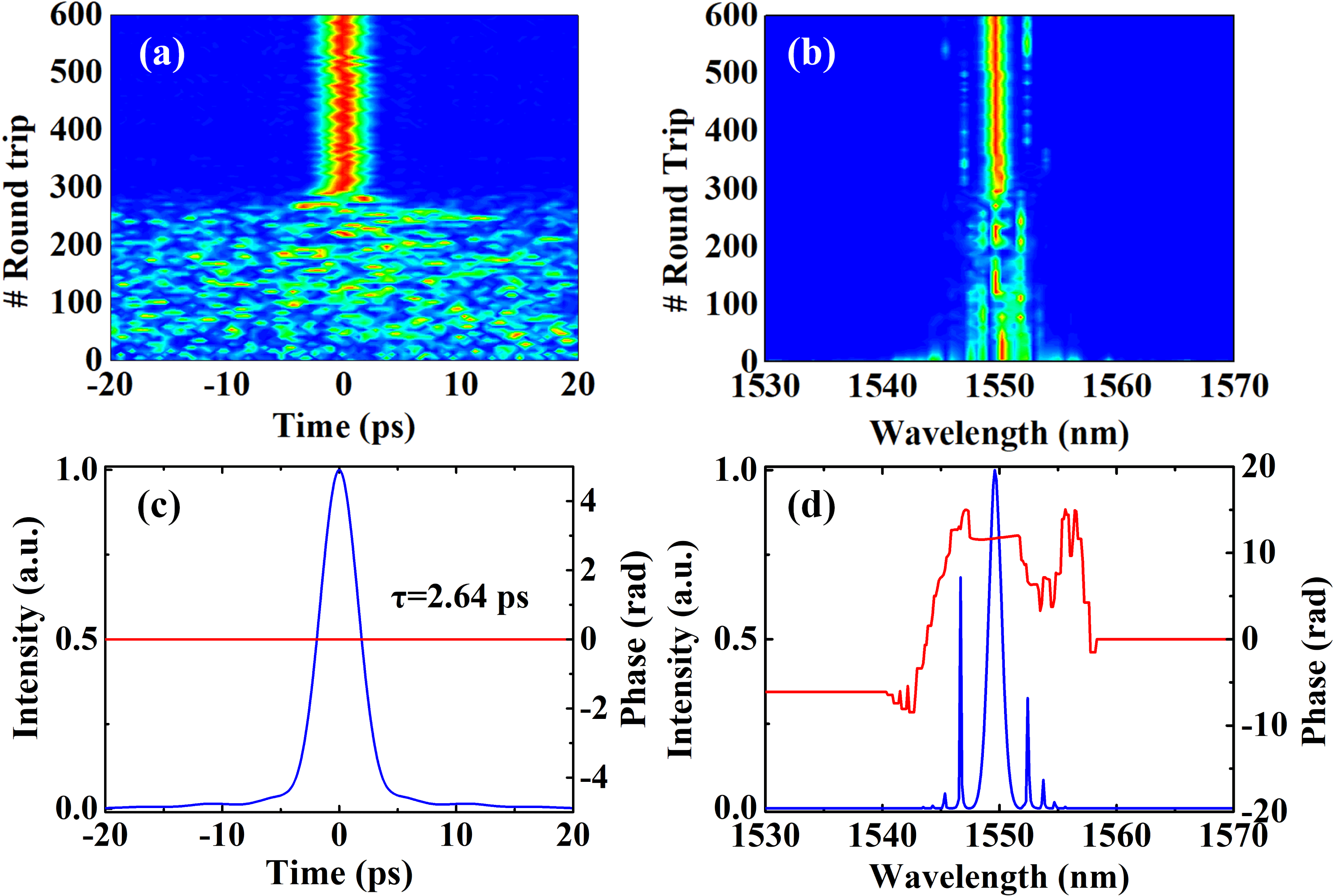
Figure 1. Results of numerical simulations without the intracavity bandpass filter. (a) Temporal and (b) spectral evolution of the pulse. (c) Temporal shape (blue curve) and phase (red curve) at the 600th round trip. (d) Spectral shape (blue curve) and phase (red curve) at the 600th round trip.
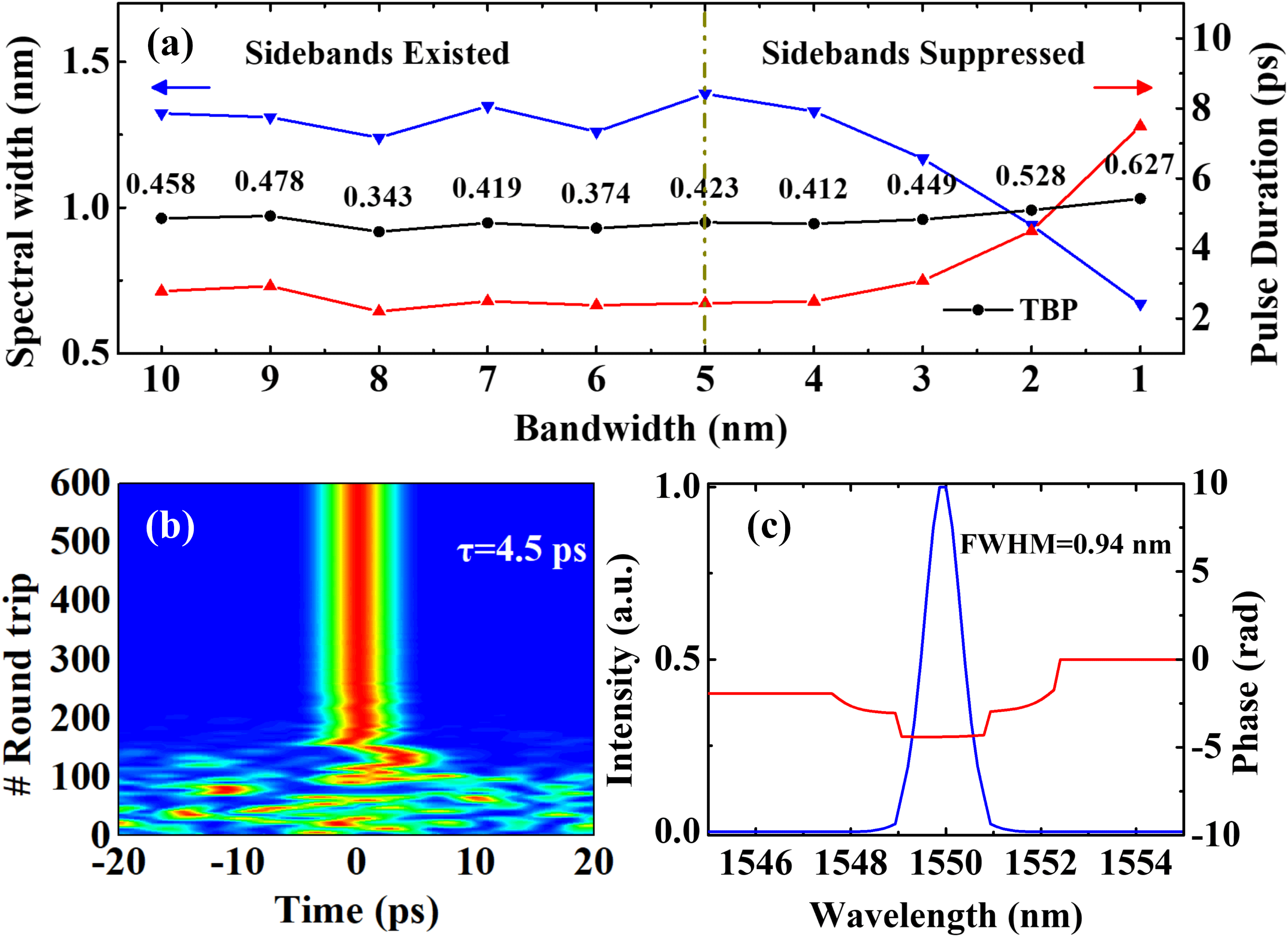
Figure 2. Results of numerical simulations with the intracavity bandpass filter. (a) Characteristics of the output pulses versus the bandwidth of the incorporated bandpass filter. (b) Evolution of the output pulses and (c) steady output spectrum and phase of the simulated oscillator with a 2-nm bandpass filter.
Figure 2 shows the numerical simulation results when the bandpass filter is employed. Steady soliton operation could always be observed as the transmission bandwidth of the bandpass filter varies from 10 to 1 nm. The blue and red curves in Figure 2(a) show the evolution of the spectral width and the temporal duration, respectively. When the bandwidth varies from 10 to 4 nm, the bandpass filter has no effect on the pulse shaping process. Notable Kelly sidebands can still be observed. As the bandwidth of the bandpass filter gradually decreases from 4 to 1 nm, the output spectral width decreases from 1.33 to 0.67 nm, and the corresponding temporal duration increases from 2.48 to 7.50 ps, respectively. An interesting phenomenon is that the TBP of the pulse increases slightly when the transmission bandwidth of the bandpass filter decreases. One possible explanation is that soliton pulses degenerate from a
![]() $\text{sech}^{2}$
shape to a Gaussian shape due to the effects of spectral filtering. Figure 2(b) shows the pulse evolution in the temporal domain with the help of a 2-nm bandpass filter. A stable soliton is achieved in 200 round trips, which is reduced by a factor
$\text{sech}^{2}$
shape to a Gaussian shape due to the effects of spectral filtering. Figure 2(b) shows the pulse evolution in the temporal domain with the help of a 2-nm bandpass filter. A stable soliton is achieved in 200 round trips, which is reduced by a factor
![]() $1/3$
relative to that when the bandpass filter is absent. The temporal duration and spectral FWHM of the soliton at the 600th round trip are 4.5 ps and 0.94 nm, as shown in Figures 2(b) and 2(c), respectively. Therefore, an appropriate bandpass filter will not only reduce the pulse build-up time, but also shape the spectral profile and effectively suppress the soliton sidebands in such long-cavity fiber lasers.
$1/3$
relative to that when the bandpass filter is absent. The temporal duration and spectral FWHM of the soliton at the 600th round trip are 4.5 ps and 0.94 nm, as shown in Figures 2(b) and 2(c), respectively. Therefore, an appropriate bandpass filter will not only reduce the pulse build-up time, but also shape the spectral profile and effectively suppress the soliton sidebands in such long-cavity fiber lasers.
3 Experimental results

Figure 3. (a) Schematic of the experimental oscillator. (b) Pulse train at a repetition rate of 1.84 MHz. (c) Radio-frequency spectra of the obtained pulses. LD: laser diode; WDM: wavelength division multiplexer; BP: bandpass filter; OFM: optical fiber mirror.
Guided by the numerical simulation, we experimentally construct a long-cavity Er-fiber laser with a 1.8-MHz repetition rate. The laser configuration based on the NALM mechanism is schematically shown in Figure 3(a). A linear arm and a nonlinear loop are bridged by a
![]() $2\times 2$
coupler with a splitting ratio of 40:60. A fiber-coupled bandpass filter with a 2-nm bandwidth and an optical fiber mirror make up the linear arm. The length of the linear arm is measured as 1.68 m. In the nonlinear loop, a segment of 0.7-m-long Er-doped fiber, a
$2\times 2$
coupler with a splitting ratio of 40:60. A fiber-coupled bandpass filter with a 2-nm bandwidth and an optical fiber mirror make up the linear arm. The length of the linear arm is measured as 1.68 m. In the nonlinear loop, a segment of 0.7-m-long Er-doped fiber, a
![]() $980/1550$
nm wavelength division multiplexer (WDM), a phase shifter, a 20:80 output coupler, and a 100-m-long PM 1550 fiber are successively spliced. The long-loop laser cavity has a total fiber length of 109.3 m. A
$980/1550$
nm wavelength division multiplexer (WDM), a phase shifter, a 20:80 output coupler, and a 100-m-long PM 1550 fiber are successively spliced. The long-loop laser cavity has a total fiber length of 109.3 m. A
![]() $-\unicode[STIX]{x03C0}/2$
nonreciprocal phase offset between the counter-propagating pulses is provided by the phase shifter to assist the self-started mode-locking. Two output ports (marked as output 1 and output 2) are used for exporting and monitoring, respectively.
$-\unicode[STIX]{x03C0}/2$
nonreciprocal phase offset between the counter-propagating pulses is provided by the phase shifter to assist the self-started mode-locking. Two output ports (marked as output 1 and output 2) are used for exporting and monitoring, respectively.
The self-started mode-locking benefits both from the long cavity length and the phase shifter. In the reflective NALM configuration, the desired phase difference for mode-locking between the bi-directional light has to approach 0 or
![]() $2\unicode[STIX]{x03C0}$
. The phase shifter is a reflection-type fiber component, which contains a Wollaston prism, a Faraday rotator, a
$2\unicode[STIX]{x03C0}$
. The phase shifter is a reflection-type fiber component, which contains a Wollaston prism, a Faraday rotator, a
![]() $\unicode[STIX]{x1D706}/8$
waveplate and a reflection mirror, as reported in Ref. [Reference Jiang, Cui, Pei, Chen, Wang and Zhang23]. The polarized beams from both ports have orthogonal polarization states and are then combined by the Wollaston prism. When the counter-propagating laser beams travel through the phase shifter, each beam receives a
$\unicode[STIX]{x1D706}/8$
waveplate and a reflection mirror, as reported in Ref. [Reference Jiang, Cui, Pei, Chen, Wang and Zhang23]. The polarized beams from both ports have orthogonal polarization states and are then combined by the Wollaston prism. When the counter-propagating laser beams travel through the phase shifter, each beam receives a
![]() $90^{\circ }$
rotation and enters opposite fiber collimators with a total phase difference of
$90^{\circ }$
rotation and enters opposite fiber collimators with a total phase difference of
![]() $\unicode[STIX]{x03C0}/2$
. Assuming that the phase shift gain of the clockwise transmitting light has a normal value, the phase shifter will provide a
$\unicode[STIX]{x03C0}/2$
. Assuming that the phase shift gain of the clockwise transmitting light has a normal value, the phase shifter will provide a
![]() $-\unicode[STIX]{x03C0}/2$
phase to the cavity. The pump-power- and fiber-length-induced phase shift is a normal value, and increasing the pump power and fiber length will raise it. Thus, at an optimized pump power, the total phase difference between the counter-propagating laser light in the nonlinear loop will approach zero to ensure the lowest cavity loss for mode-locking.
$-\unicode[STIX]{x03C0}/2$
phase to the cavity. The pump-power- and fiber-length-induced phase shift is a normal value, and increasing the pump power and fiber length will raise it. Thus, at an optimized pump power, the total phase difference between the counter-propagating laser light in the nonlinear loop will approach zero to ensure the lowest cavity loss for mode-locking.
When the phase shifter is absent, mode-locking operation cannot be achieved even with the maximum available pumping power (400 mW) of the laser diode and active mechanical perturbation. With the help of a
![]() $-\unicode[STIX]{x03C0}/2$
phase shifter, the reflection efficiency increases with the pumping power, and reaches its maximum value as the nonlinear phase accumulation approaches
$-\unicode[STIX]{x03C0}/2$
phase shifter, the reflection efficiency increases with the pumping power, and reaches its maximum value as the nonlinear phase accumulation approaches
![]() $\unicode[STIX]{x03C0}/2$
. Mode-locking operation is initiated in the multiple-pulse operation regime when the pumping power at 976 nm increases to 70 mW. At 24-mW pumping power, single-pulse operation at the fundamental repetition rate is achieved. Figure 3(b) shows the soliton pulse train with a 1.84-MHz repetition rate recorded by an oscilloscope. The average power is measured to be
$\unicode[STIX]{x03C0}/2$
. Mode-locking operation is initiated in the multiple-pulse operation regime when the pumping power at 976 nm increases to 70 mW. At 24-mW pumping power, single-pulse operation at the fundamental repetition rate is achieved. Figure 3(b) shows the soliton pulse train with a 1.84-MHz repetition rate recorded by an oscilloscope. The average power is measured to be
![]() $32~\unicode[STIX]{x03BC}\text{W}$
, corresponding to a pulse energy of 17.4 pJ. By adding 150-m PM 1550 fiber, the pulse repetition rate is further decreased to 0.8 MHz, shown as the red curve in Figure 3(c). Since the generated pulse has a relatively low energy, the signal-to-noise ratio of the RF spectrum is approximately 50 dB, and a slight noise component is observed.
$32~\unicode[STIX]{x03BC}\text{W}$
, corresponding to a pulse energy of 17.4 pJ. By adding 150-m PM 1550 fiber, the pulse repetition rate is further decreased to 0.8 MHz, shown as the red curve in Figure 3(c). Since the generated pulse has a relatively low energy, the signal-to-noise ratio of the RF spectrum is approximately 50 dB, and a slight noise component is observed.

Figure 4. Comparison of the spectra with (blue curves) and without (red curves) the bandpass filter when the oscillator operates in the (a) multiple-pulse and (b) single-pulse operation regimes. For a better comparison, the blue curves are red-shifted by 6.4 nm.
To confirm the spectral filtering effect of the bandpass filter, we remove it from the cavity. Multiple-pulse mode-locking builds up at a 100-mW pump power, and single-pulse operation with the lowest pump power is achieved at 20 mW. Figure 4 shows the output spectra obtained from output 1. Without the bandpass filter, the output spectra exhibit notable sidebands, both in multiple-pulse and single-pulse operation, as shown by the red curves in Figure 4. In the spectral domain, the output pulses are both centered at 1556.4 nm with an FWHM of 1.48 nm. The separations of the first- and second-order sidebands from the central wavelength are measured as 2.51 and 3.87 nm, respectively. The blue curves in Figure 4 show the output spectra of the laser incorporated with a bandpass filter. The sharp spectral peak in Figure 4(a) indicates that the pump power is too great to induce continuous wave oscillation. The single-pulse operation case has a spectral width of 1 nm, shown as the blue curve in Figure 4(b). Furthermore, over a larger wavelength range from 1520 to 1580 nm, the ASE components at 1530 nm are suppressed to better than 5 dB and the inevitable soliton sidebands are effectively eliminated by the bandpass filter incorporated in the long-cavity oscillator.
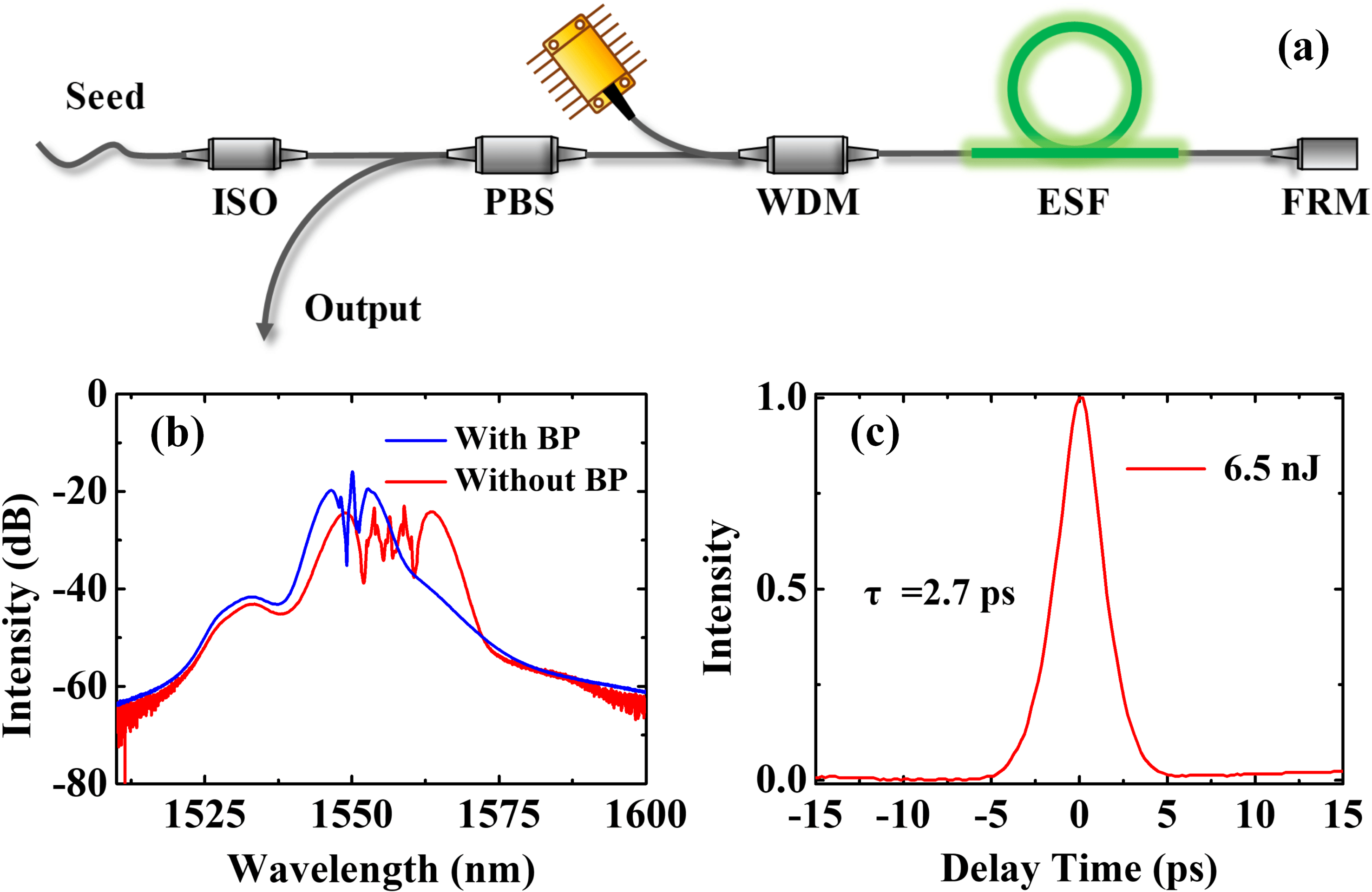
Figure 5. (a) Schematic configuration of the pre-amplifier. ISO: isolator; PBS: polarized beam splitter; ESF: Er-doped single-mode fiber; FRM: Faraday rotation mirror. (b) Spectral profiles when the intracavity bandpass filter in the laser oscillator is activated (blue curve) or removed (red curve). (c) Autocorrelation trace measured by the PulseCheck.
Since the output pulse is too weak to be measured by the autocorrelator, a single-mode-fiber amplifier is applied to pre-amplify the output pulses (see Figure 5(a)). This fiber amplifier has a dual-pass configuration, which has the benefit of suppressing ASE and polarization perturbation[Reference Hao, Zhang, Sun, Chen, Guo, Wang, Guo, Yang and Zeng24]. With 120-mW pump power, the pulse energy of the seed laser is boosted from 17.4 pJ to 6.5 nJ. Figure 5(b) compares the amplified spectra of the seed pulse with or without the intracavity bandpass filter. The amplified spectra are broadened by self-phase modulation (SPM). When the bandpass filter is removed, the amplified laser exhibits more serious spectral modulation due to the shorter seed pulses. In the time domain, no matter whether the bandpass filter is incorporated or not, the measured pulse duration is around 2.7 ps, as shown in Figure 5(c).
The output pulse of the long-cavity oscillator has a spectral width of 1.48 nm, corresponding to a transform-limited (TFL) pulse width of 2.4 ps (assuming a Gaussian profile). As reported in Ref. [Reference Tamura, Doerr, Haus and Ippen25], the soliton characteristics do not change as the sidebands are suppressed by an intracavity bandpass filter. Another aspect is that the total fiber length of the pre-amplifier is only about 110 cm (including 70-cm ESF and 40-cm SMF-28 fibers). Thus, the total fiber dispersion is negligible for pulse temporal stretching. Therefore, the pulse duration of the oscillator is nearly the same as the pre-amplified pulses.

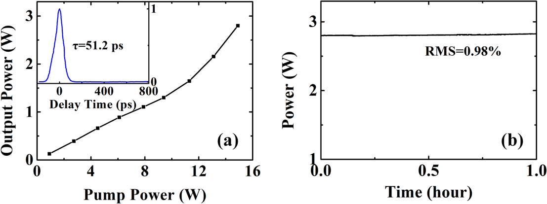
Figure 6. (a) Slope efficiency of the double-cladding amplifier. Inset: autocorrelation trace of the amplified pulses. (b) Average power stability.
To meet the requirement for high pulse energy applications, the pre-amplified pulse is further amplified by a double-clad fiber main amplifier, which is similar to the amplifier used in Ref. [Reference Han, Jang, Kim, Kim and Kim26]. The length of the Er/Yb co-doped fiber (PM-EYDF-12/130-HE, Nufern) is optimized to 2.3 m to provide sufficient gain and avoid detrimental nonlinear phase accumulation. With a 14.9-W pump power, the average power of the output pulses is amplified to 2.8 W, corresponding to a slope efficiency of 18.8% (see Figure 6(a)). Due to the co-effect of dispersion and nonlinearity, the amplified pulse is stretched to 51 ps (see the inset of Figure 6(a)). Figure 6(b) shows the stability of the output power over an hour. Owing to the environmentally stable architecture, the root mean square (RMS) of the output power is measured to be 0.98%.
For outdoor applications, the fiber laser system (including fiber chain, electrical controller and power supply) is integrated into an aluminum box with dimensions of
![]() $382.5~\text{mm}\times 320~\text{mm}\times 123~\text{mm}$
. In combination with the all-PM-fiber architecture, the laser system could be operated reliably without any adjustment after transportation to another laboratory at a distance of 2000 km away. Furthermore, to investigate the effect of thermal variations on the laser stability, the whole laser system is placed in an incubator. During the temperature test, the fiber oscillator and the pre-amplifier are activated, while the main amplifier is turned off. The mode-locking operation remains stable for more than 6 h, as shown in Figure 7. Because the efficiency of
$382.5~\text{mm}\times 320~\text{mm}\times 123~\text{mm}$
. In combination with the all-PM-fiber architecture, the laser system could be operated reliably without any adjustment after transportation to another laboratory at a distance of 2000 km away. Furthermore, to investigate the effect of thermal variations on the laser stability, the whole laser system is placed in an incubator. During the temperature test, the fiber oscillator and the pre-amplifier are activated, while the main amplifier is turned off. The mode-locking operation remains stable for more than 6 h, as shown in Figure 7. Because the efficiency of
![]() $\text{Er}^{3+}$
is highly related to the temperature, the output power increases from 3 to 3.4 mW as the temperature increases from 10 to
$\text{Er}^{3+}$
is highly related to the temperature, the output power increases from 3 to 3.4 mW as the temperature increases from 10 to
![]() $40\,^{\circ }\text{C}$
. The more severe fluctuations of output power at
$40\,^{\circ }\text{C}$
. The more severe fluctuations of output power at
![]() $10\,^{\circ }\text{C}$
are because the refrigeration capacity of the incubator is not as good as its heating capacity. Overall, our long-cavity laser system exhibits excellent robustness and long-term stability.
$10\,^{\circ }\text{C}$
are because the refrigeration capacity of the incubator is not as good as its heating capacity. Overall, our long-cavity laser system exhibits excellent robustness and long-term stability.
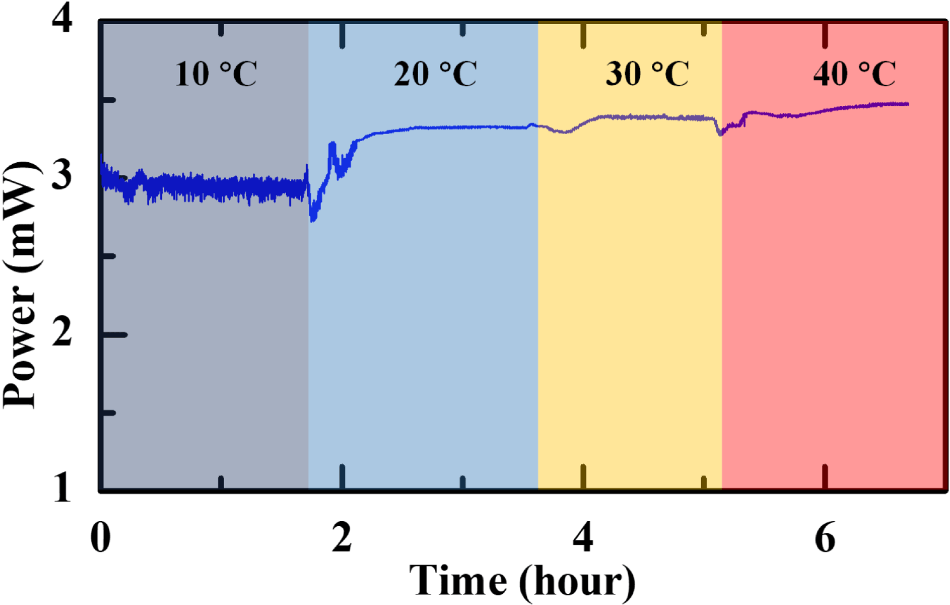
Figure 7. Output power of the laser system in an incubator as the temperature changes.
4 Conclusions
In conclusion, we have demonstrated an environmentally stable Er-fiber ultrafast laser operating at a quite low repetition rate. With the assistance of a phase-biased shifter in a long nonlinear loop, the Er-fiber laser oscillator realizes self-started mode-locking at a low threshold and delivers pulses with a 17-pJ energy at a 1.84-MHz repetition rate. The longer than 100 m PM fiber, which has giant anomalous dispersion, forces the mode-locking pulse laser to operate in the soliton regime. Numerical simulation guides us to suppress the Kelly sidebands by using an intracavity bandpass filter. Furthermore, the seed pulses with eliminated ASE noise are boosted to an average power of 2.8 W, yielding a pulse energy of
![]() $1.5~\unicode[STIX]{x03BC}\text{J}$
. This laser system exhibits long-term stability and reliability, and will be suitable for various lidar measurements and unambiguous long-distance ranging.
$1.5~\unicode[STIX]{x03BC}\text{J}$
. This laser system exhibits long-term stability and reliability, and will be suitable for various lidar measurements and unambiguous long-distance ranging.
Acknowledgements
This work is supported by the National Key Research and Development Program (No. 2018YFB0407100), National Natural Science Foundation of China (Nos. 11434005 and 11621404), and Key Project of Shanghai Education Commission (No. 2017-01-07-00-05-E00021).


