


1. Introduction
Capsules are droplets enclosed by a thin elastic membrane and are found in various situations, such as red blood cells and fish eggs in nature, cosmetics and agricultural products in industrial processes. They are therefore widely used in fields such as bioengineering and chemical engineering. In the agricultural field, Friedman & Mualem (Reference Friedman and Mualem1994) conducted a study on the diffusion of fertilisers into soil from capsules. They investigated the influence of membrane conductance and capsule density on the fertiliser release rate, and managed to achieve the desired release rate using their proposed model. In the field of biomedical engineering, encapsulation techniques have been used for targeted drug delivery (Shi & Tan Reference Shi and Tan2002; Skirtach et al. Reference Skirtach, Karageorgiev, Bédard, Sukhorukov and Möhwald2008; Bhujbal, de Vos & Niclou Reference Bhujbal, de Vos and Niclou2014; Kamat et al. Reference Kamat, Palin, Lubelli and Schlangen2024), and controlled release of the drug in capsules has become an important issue. To consider this issue, controlled release of certain substances has been achieved by varying the permeability of the capsule membrane. For example, Kamat et al. (Reference Kamat, Palin, Lubelli and Schlangen2024) changed the ratio of complexing chitosan and calcium-alginate in the capsule membrane, and controlled the release rate of NaFeCN within the mortar. Skirtach et al. (Reference Skirtach, Karageorgiev, Bédard, Sukhorukov and Möhwald2008) made aggregates of gold nanoparticles in polyelectrolyte shells, and changed the capsule permeability by near-infrared illumination. Bhujbal et al. (Reference Bhujbal, de Vos and Niclou2014) used liposomes to contain active cytotoxic compounds, and managed to release those compounds in the long term to treat brain tumours. They changed the ratio of phospholipid and cholesterol in liposomes to obtain different release rates. Shi & Tan (Reference Shi and Tan2002) conducted research on encapsulating vitamin $\text{D}_2$
within a capsule made of chitosan. They found that the capsule can achieve sustained release in the intestine juice and delayed release in the gastric environment by changing the molecular weight and concentration of chitosan. Despite the advent of sophisticated control techniques for membrane permeability by employing light irradiation and chemical concentration fields, viscous forces also play an important role in membrane mechanics. The viscous stress exerted on the capsule membrane by the surrounding fluid flow has the potential to cause damage to the membrane and result in the unintended release of drugs. Consequently, it is imperative to undertake a comprehensive study of the motion and deformation of capsules within the context of fluid flow.
$\text{D}_2$
within a capsule made of chitosan. They found that the capsule can achieve sustained release in the intestine juice and delayed release in the gastric environment by changing the molecular weight and concentration of chitosan. Despite the advent of sophisticated control techniques for membrane permeability by employing light irradiation and chemical concentration fields, viscous forces also play an important role in membrane mechanics. The viscous stress exerted on the capsule membrane by the surrounding fluid flow has the potential to cause damage to the membrane and result in the unintended release of drugs. Consequently, it is imperative to undertake a comprehensive study of the motion and deformation of capsules within the context of fluid flow.
Theories of capsule dynamics have been developed sufficiently by Barthès-Biesel, Pozrikidis and their colleagues. As outlined in the seminal work of Pozrikidis (Reference Pozrikidis2010), an overview of capsule dynamics can be found in the Introduction. Barthès-Biesel (Reference Barthès-Biesel1980) conducted an analytical study on the dynamics of a microcapsule under linear shear flow, deriving an analytical solution in the limit of small deformation. In order to extend this to large deformations, Barthès-Biesel et al. (Reference Barthès-Biesel, Diaz and Dhenin2002) investigated the mechanical properties of two-dimensional hyperelastic materials with different constitutive laws. Lac et al. (Reference Lac, Barthès-Biesel, Pelekasis and Tsamopoulos2004) then undertook a numerical investigation into a spherical capsule in three-dimensional Stokes flow. The numerical results obtained by the researchers were in agreement with the prediction made by Barthès-Biesel et al. (Reference Barthès-Biesel, Diaz and Dhenin2002), although the computation became unstable in the case of large deformation. As demonstrated by Walter et al. (Reference Walter, Salsac, Barthès-Biesel and Tallec2010), the development of a coupled finite element and boundary element method has enabled the stabilisation of computations. This methodology has been employed successfully to quantify the transition capillary numbers of different deformation regimes for various constitutive laws.
Foessel et al. (Reference Foessel, Walter, Salsac and Barthès-Biesel2011) have also investigated the influence of the viscosity ratio of internal to external fluids. Their findings indicate that the internal viscosity exerts a significant effect on capsule deformation when the internal viscosity is smaller than that of the external environment. Conversely, when the internal viscosity exceeds that of the external environment, the internal motion’s decelerating effect on the capsule deformation is diminished. Omori et al. (Reference Omori, Imai, Yamaguchi and Ishikawa2012) conducted a numerical study of a non-spherical capsule in creeping shear flow, the results of which demonstrate that the orientation of a non-spherical capsule is subject to variation under time reversal, and that this variation can be controlled by adjusting the background flow strength or unsteadiness. Dupont et al. (Reference Dupont, Tallec, Barthès-Biesel, Vidrascu and Salsac2015) conducted an investigation into the influence of the bending resistance of a spherical capsule. The findings of the study indicate that the wrinkle wavenumber of the membrane is contingent solely on the bending resistance, and that the bending resistance exerts an influence on local buckling. However, its effect on shape and deformation can be disregarded. Matsunaga et al. (Reference Matsunaga, Imai, Yamaguchi and Ishikawa2015) investigated capsule deformation under oscillating shear flow, finding that deformation is larger under oscillation than under steady shear flow, and that the overshoot is also larger when the capsule is softer. Matsunaga et al. (Reference Matsunaga, Imai, Yamaguchi and Ishikawa2016) also conducted a numerical investigation of the capsule dynamics in their dense suspensions. It was observed that as the volume fraction of the capsules increased, the capsule deformation increased correspondingly; however, the angle of inclination of the capsules with respect to the flow direction decreased.
However, as the deformation increases, the capsule will inevitably sustain damage due to the substantial deformation that it undergoes. Consequently, research into membrane damage due to mechanical stress has been undertaken both experimentally and theoretically (Chang & Olbricht Reference Chang and Olbricht1993; Walter, Rehage & Leonhard Reference Walter, Rehage and Leonhard2001; Husmann et al. Reference Husmann, Rehage, Dhenin and Barthès-Biesel2005; Koleva & Rehage Reference Koleva and Rehage2012; Leopércio et al. Reference Leopércio, Michelon and Carvalho2021; Jambon-Puillet, Jones & Brun Reference Jambon-Puillet, Jones and Brun2020). As demonstrated by Chang & Olbricht (Reference Chang and Olbricht1993), the insertion of a capsule into Couette flow resulted in the observation of capsule deformation. Furthermore, capsule break-up was observed when the deformation induced by the flow reached a sufficient magnitude. Walter et al. (Reference Walter, Rehage and Leonhard2001) conducted experiments on a capsule within shear flow, observing shape oscillation and membrane folding phenomena, which have the potential to lead to fatigue mechanisms. Leopércio et al. (Reference Leopércio, Michelon and Carvalho2021) conducted a microfluidic experiment in which they observed the flow of microcapsules through constricted channels. The rupture of microcapsules was found to be initiated by stress caused by deformation, which in turn is influenced by capsule diameter and thickness. Jambon-Puillet et al. (Reference Jambon-Puillet, Jones and Brun2020) conducted experiments on the impact of capsules against rigid walls. The impact velocity of the capsules was found to have a significant effect on their deformation and rupture. Furthermore, the viscosity of the surrounding fluid was found to influence the critical velocity at which rupture occurs.
Moreover, Husmann et al. (Reference Husmann, Rehage, Dhenin and Barthès-Biesel2005) exposed a microcapsule to centrifugal forces, and observed its destruction as a result of the substantial centrifugal force applied. The rupture of the capsule was found to occur exclusively at the pole ends. As stated by Koleva & Rehage (Reference Koleva and Rehage2012), the wrinkling and break-up of microcapsules in extreme large deformation was observed through the introduction of microcapsules into shear flow. Furthermore, Grandmaison, Brancherie & Salsac (Reference Grandmaison, Brancherie and Salsac2021) presented a numerical model of capsule damage and rupture, considering damage behaviour within the framework of continuum damage mechanics. The damage model employed was of the isotropic brittle damage type, with the membrane damage state being dependent on the history of loading.
The flow applied to a capsule is not limited to background flows; it could also be the flow created by external forces or microswimmers of the same size as the capsule. In their study, Kree, Rückert & Zippelius (Reference Kree, Rückert and Zippelius2021) examined the impact of diverse external forces on the locomotion of a droplet, encompassing a single point force, a force dipole, and even the forces generated by a biflagellate swimmer. In the context of microswimmers, the squimer model developed by Lighthill (Reference Lighthill1952) has been seminal. This model, the basis of the present study, propels itself by generating small deformations on the particle surface. It was later expanded upon by Blake (Reference Blake1971) to create a more generalised microswimmer model, corresponding to a microswimmer that propels itself by generating slip velocities on its surface (Ishikawa Reference Ishikawa2024a ). This is the best-known self-propelled particle model in microfluid dynamics. As demonstrated in the works of Reigh et al. (Reference Reigh, Zhu, Gallaire and Lauga2017) and Huang, Omori & Ishikawa (Reference Huang, Omori and Ishikawa2020), the interaction between squirmers and droplets has been the subject of numerous studies. In particular, Reigh et al. (Reference Reigh, Zhu, Gallaire and Lauga2017) conducted a numerical simulation of a squirmer enclosed within a droplet, thereby demonstrating that the enclosed squirmer is capable of propelling the droplet through hydrodynamic interactions. Furthermore, the co-swimming state exhibited by both the squirmer and the droplet was found to be stable. As stated by Huang et al. (Reference Huang, Omori and Ishikawa2020), a self-propelled droplet model analogous to a squirmer has also been documented. This model demonstrates that the collective swimming of squirmers within a drop engenders a flow on the drop’s surface, which subsequently swims due to its slip velocity. The aforementioned models operated under the assumption that the surface tension of the droplet is considerably larger than the viscous stress of the flow. Consequently, the deformation or breakdown of the droplet was not taken into consideration. In considering the deformation of droplets due to a microswimmer’s swimming, Kawakami & Vlahovska (Reference Kawakami and Vlahovska2025) conducted an analytical study of an active particle confined within a spherical, deformable droplet. It was established that an active particle offset from the centre of the drop can disrupt the symmetry, resulting in shape changes and droplet displacement.
Additionally, there has been considerable research activity on the deformation of capsules and vesicles due to the movement of microswimmers (Dias & Powers Reference Dias and Powers2013; Daddi-Moussa-Ider et al. Reference Daddi-Moussa-Ider, Goh, Liebchen, Hoell, Mathijssen, Guzmán-Lastra, Scholz, Menzel and Löwen2019; Takatori & Sahu Reference Takatori and Sahu2020; Vutukuri et al. Reference Vutukuri, Hoore, Abaurrea-Velasco, van Buren, Dutto, Auth, Fedosov, Gompper and Vermant2020; Nagard et al. Reference Le Nagard, Brown, Dawson, Martinez, Poon and Staykova2022; Fessler et al. Reference Fessler, Wittmann, Simmchen and Stocco2024; Wu, Omori & Ishikawa Reference Wu, Omori and Ishikawa2024). Dias & Powers (Reference Dias and Powers2013) conducted a study on the locomotion of an infinitely long swimmer in proximity to a deformable boundary that separates the fluid into two distinct parts. The direction of fluid flow can be controlled by manipulating the viscosity ratio on either side of the swimmer. Subsequently, when microswimmers are located outside of capsules and vesicles, Daddi-Moussa-Ider et al. (Reference Daddi-Moussa-Ider, Goh, Liebchen, Hoell, Mathijssen, Guzmán-Lastra, Scholz, Menzel and Löwen2019) developed a simple model to describe the interaction of a self-driven spherical particle with a minimal membrane system, allowing for both penetration and trapping. It has been demonstrated that the active particle may either become trapped in proximity to the membrane or penetrate through it. In the latter case, the membrane may be permanently destroyed or recover its initial shape by means of self-healing. Concurrently, Fessler et al. (Reference Fessler, Wittmann, Simmchen and Stocco2024) investigated the interaction of Janus colloids with giant vesicles, leading to the observation of endocytosis. The study indicated the pivotal function of far-field hydrodynamic interaction, determining that puller-type swimmers possess the capacity to target giant vesicles, deform their membranes, and achieve stable engulfment. In addition, a numerical simulation of a squirmer swimming in a suspension of red blood cells was conducted by Wu et al. (Reference Wu, Omori and Ishikawa2024), which revealed that a squirmer can swim faster than a passive swimmer by repelling red blood cells to the side of the squirmer. Furthermore, the influence of microswimmers inside capsules and vesicles is also investigated. In their research, Vutukuri et al. (Reference Vutukuri, Hoore, Abaurrea-Velasco, van Buren, Dutto, Auth, Fedosov, Gompper and Vermant2020) conducted numerical simulations, placing self-propelled particles within giant unilamellar vesicles, and observing the resultant non-equilibrium shapes and active membrane fluctuations induced by the particles. Similarly, Takatori & Sahu (Reference Takatori and Sahu2020) conducted experiments but replaced the particles with bacteria and derived an analytical solution. Subsequently, Nagard et al. (Reference Le Nagard, Brown, Dawson, Martinez, Poon and Staykova2022) encapsulated bacteria within giant lipid vesicles, thereby forming a tube-like structure that can transform into an effective helical flagellum and propel the vesicle. The development of a theoretical model to estimate the propulsive force and efficiency is also reported.
Furthermore, external magnetic fields and lasers have been utilised to regulate the movement of the swimmers. For instance, as cited in Huang et al. (Reference Huang, Sakar, Petruska, Pané and Nelson2016), the incorporation of magnetic particles into a near-infrared responsive material has enabled the fabrication of a self-folding microrobot that is powered by magnetism. Lozano et al. (Reference Lozano, Hagen, Löwen and Bechinger2016) conducted experiments by subjecting a spherical active colloid exposed to an inhomogeneous laser field. The outcomes of these studies demonstrate that the transportation of active colloids can be directed towards lower laser intensity, and that the motion of active colloids can be modulated by adjusting the laser field.
Notwithstanding the exhaustive research that has been carried out in this field, the precise mechanisms by which microswimmers are confined within elastic capsules, and the effects of the flow generated by them on the capsule membrane, remain to be elucidated. The present study focuses on the hydrodynamic interaction between the capsule membrane and the microswimmer. This is done with a view to determining the effect on capsule membrane damage and rupture. Moreover, the objective of the present study is to develop a damage control technique that utilises an external magnetic torque. In § 2, we present our numerical models of a capsule, the damage behaviour of the capsule membrane and a microswimmer, together with the fundamental equations and our numerical method. In § 3, we present the simulation results obtained under various conditions, and provide a range of different capsule states. In § 4, an external magnetic field is imposed in order to control the squirmer orientation and to investigate damage control techniques using the external magnetic torque. The conclusions of this study are outlined in § 5.
2. Governing equations and numerical method
Consider a capsule immersed in an unbounded incompressible Newtonian liquid with viscosity $\mu$
and density
$\mu$
and density $\rho$
. The capsule contains the same liquid as the exterior and a spherical microswimmer with radius
$\rho$
. The capsule contains the same liquid as the exterior and a spherical microswimmer with radius $a_s$
, as shown in figure 1(a). The reference shape of the capsule is assumed to be a sphere with radius
$a_s$
, as shown in figure 1(a). The reference shape of the capsule is assumed to be a sphere with radius $a_c$
. Due to the small size of both capsule and microswimmer, the Reynolds number is small enough that the flow field can be considered as Stokes flow, where inertia can be neglected. The thickness of the capsule membrane is sufficiently small compared to its size and curvature radius, thus the membrane is considered as a two-dimensional hyperelastic material. To estimate the damage to the capsule due to hydrodynamic interaction with the microswimmer, we employ a continuum-based isotropic brittle damage model, as described previously by Grandmaison et al. (Reference Grandmaison, Brancherie and Salsac2021).
$a_c$
. Due to the small size of both capsule and microswimmer, the Reynolds number is small enough that the flow field can be considered as Stokes flow, where inertia can be neglected. The thickness of the capsule membrane is sufficiently small compared to its size and curvature radius, thus the membrane is considered as a two-dimensional hyperelastic material. To estimate the damage to the capsule due to hydrodynamic interaction with the microswimmer, we employ a continuum-based isotropic brittle damage model, as described previously by Grandmaison et al. (Reference Grandmaison, Brancherie and Salsac2021).
The ensuing sections are to be perused with a view to acquiring an understanding of the governing equations of fluid–solid interactions between the capsule and the microswimmer.
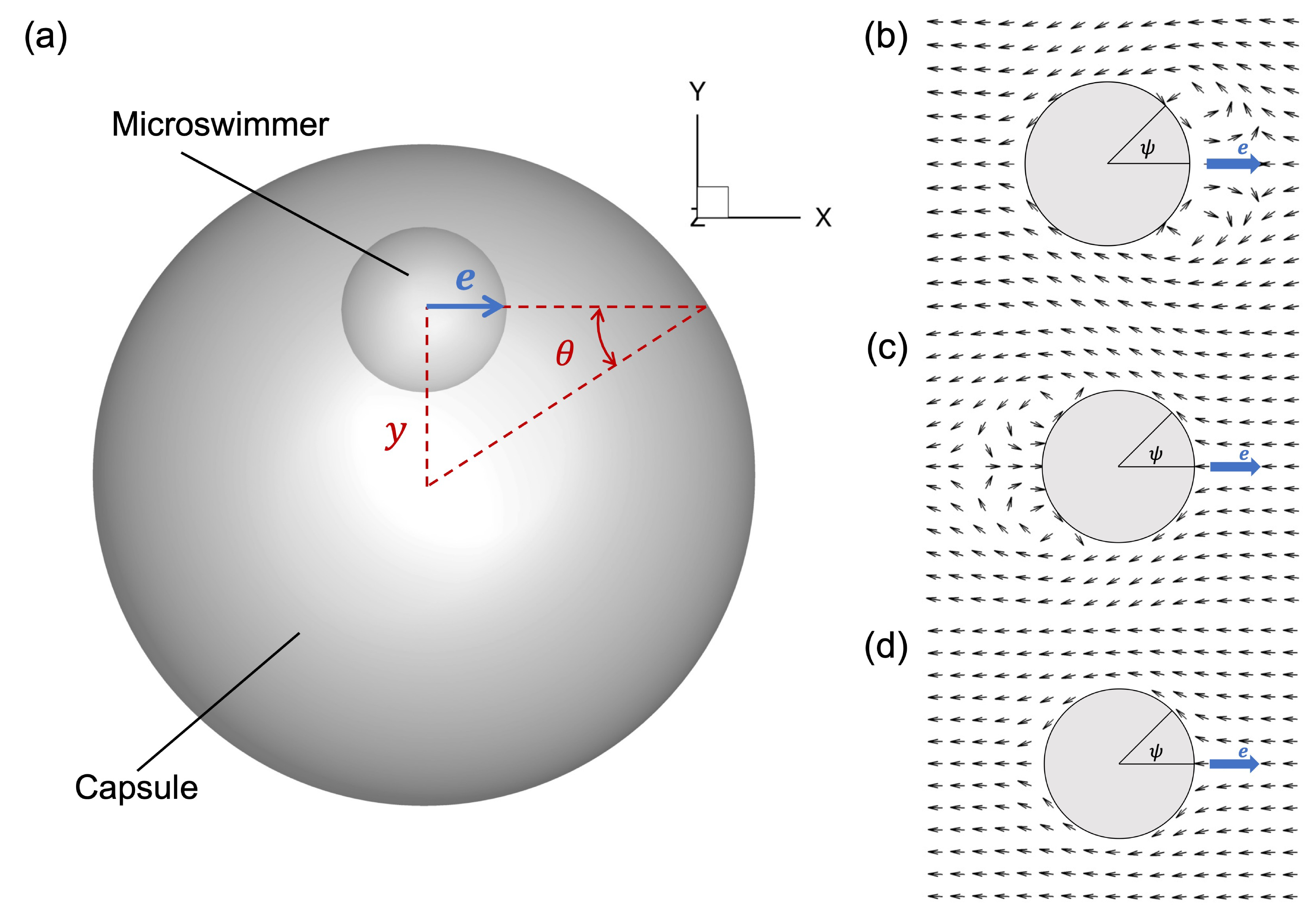
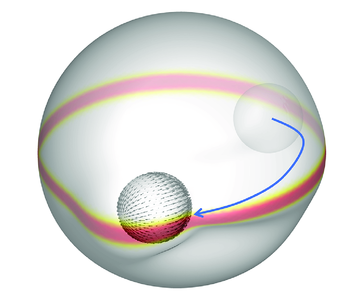
Figure 1. Problem setting of the numerical simulation. (a) A spherical capsule of radius $a_c$
is immersed in an infinite Newtonian liquid of density
$a_c$
is immersed in an infinite Newtonian liquid of density $\rho$
and viscosity
$\rho$
and viscosity $\mu$
(the centre of mass of the capsule corresponds to the Cartesian origin). The inner liquid of the capsule is assumed to be the same as the external liquid. A squirmer of radius
$\mu$
(the centre of mass of the capsule corresponds to the Cartesian origin). The inner liquid of the capsule is assumed to be the same as the external liquid. A squirmer of radius $a_s$
is contained within the capsule, and the size ratio is fixed to
$a_s$
is contained within the capsule, and the size ratio is fixed to $a_c/a_s = 4$
. The squirmer orientation
$a_c/a_s = 4$
. The squirmer orientation $\boldsymbol{e}$
is initially set to
$\boldsymbol{e}$
is initially set to $(1,0,0)$
, and the initial centre of the squirmer is
$(1,0,0)$
, and the initial centre of the squirmer is $(0,y,0)$
. The initial incidence angle
$(0,y,0)$
. The initial incidence angle $\theta$
is determined by adjusting the initial position
$\theta$
is determined by adjusting the initial position $y$
. (b–d) The flow created by the squirmer with different swimming modes: (b) a pusher-type squirmer (
$y$
. (b–d) The flow created by the squirmer with different swimming modes: (b) a pusher-type squirmer ( $\beta = -3$
); (c) a puller-type squirmer (
$\beta = -3$
); (c) a puller-type squirmer ( $\beta = 3$
); and (d) a neutral-type squirmer (
$\beta = 3$
); and (d) a neutral-type squirmer ( $\beta = 0$
).
$\beta = 0$
).
2.1. Membrane mechanics
Assume that the membrane thickness is sufficiently small for the membrane to be considered as a two-dimensional hyperelastic material. The membrane surface $S$
is determined by two surface curvilinear coordinates (
$S$
is determined by two surface curvilinear coordinates ( $\xi ^1,\xi ^2$
). The membrane material points in the reference and deformed states are given by
$\xi ^1,\xi ^2$
). The membrane material points in the reference and deformed states are given by $\boldsymbol{X}(\xi ^1,\xi ^2)$
and
$\boldsymbol{X}(\xi ^1,\xi ^2)$
and $\boldsymbol{x}(\boldsymbol{X},t)$
, respectively. The gradient of transformation, denoted by
$\boldsymbol{x}(\boldsymbol{X},t)$
, respectively. The gradient of transformation, denoted by $\unicode{x1D641}$
, is given by (Pozrikidis Reference Pozrikidis2010)
$\unicode{x1D641}$
, is given by (Pozrikidis Reference Pozrikidis2010)
 \begin{equation} {\rm d}\boldsymbol{x}=\unicode{x1D641} \cdot {\rm d}\boldsymbol{X}. \end{equation}
Then the local deformation of the membrane can be measured by the Green–Lagrange strain tensor
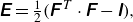 \begin{equation} \unicode{x1D640}=\tfrac {1}{2}\big(\unicode{x1D641}^{\kern1pt T} \cdot \unicode{x1D641}-\unicode{x1D644}\big), \end{equation}
where $\unicode{x1D644}$
is the identity tensor. And two invariants of the transformation are given by
$\unicode{x1D644}$
is the identity tensor. And two invariants of the transformation are given by
 \begin{equation} I_1=\lambda _1^2+\lambda _2^2-2, \quad I_2=\lambda _1^2\lambda _2^2-1=J_s^2-1, \end{equation}
where $\lambda _1,\lambda _2$
are the principal dilation ratios, and the Jacobian
$\lambda _1,\lambda _2$
are the principal dilation ratios, and the Jacobian $J_s=\lambda _1 \lambda _2$
expresses the ratio of the deformed to the undeformed surface areas. Assuming that the membrane is an isotropic material, Cauchy tension tensor
$J_s=\lambda _1 \lambda _2$
expresses the ratio of the deformed to the undeformed surface areas. Assuming that the membrane is an isotropic material, Cauchy tension tensor $\unicode{x1D64F}$
can be related to a strain energy function per unit area of undeformed membrane
$\unicode{x1D64F}$
can be related to a strain energy function per unit area of undeformed membrane $\omega _s(I_1,I_2)$
by the equation
$\omega _s(I_1,I_2)$
by the equation
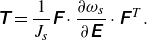 \begin{equation} \unicode{x1D64F}=\frac {1}{J_s} \unicode{x1D641} \cdot \frac {\partial \omega _s}{\partial \unicode{x1D640}} \cdot \unicode{x1D641}^{\kern1pt T}. \end{equation}
The behaviour of the capsule membrane is described by means of a neo-Hookean (NH) law, the strain energy function of which is given by
 \begin{equation} \omega _s^{NH}=\frac {G_s}{2} \left (I_1-1+\frac {1}{I_2+1}\right ), \end{equation}
where $G_s$
is the surface elastic shear modulus.
$G_s$
is the surface elastic shear modulus.
In the case of an infinitely thin membrane, the inertia of the membrane can be considered negligible. Consequently, the motion of the membrane is governed by local mechanical equilibrium:
 \begin{equation} \boldsymbol{q}_e + \nabla _s \cdot \unicode{x1D64F} = \boldsymbol{0}, \end{equation}
where $\boldsymbol{q}_e$
is the surface load due to membrane in-plane stretch, and
$\boldsymbol{q}_e$
is the surface load due to membrane in-plane stretch, and $\nabla _s$
is the surface divergence operator. By applying the virtual work principle, the equilibrium equation (2.6) can be written in a weak form (Walter et al. Reference Walter, Salsac, Barthès-Biesel and Tallec2010)
$\nabla _s$
is the surface divergence operator. By applying the virtual work principle, the equilibrium equation (2.6) can be written in a weak form (Walter et al. Reference Walter, Salsac, Barthès-Biesel and Tallec2010)
 \begin{equation} \iint _s \hat{\boldsymbol{v}} \cdot \boldsymbol{q}_e\, {\rm d}S-\iint _s\hat{\boldsymbol{\epsilon }}(\hat{\boldsymbol{v}}):\unicode{x1D64F}\,{\rm d}S=0, \end{equation}
where $\boldsymbol{\hat {v}}$
and
$\boldsymbol{\hat {v}}$
and $\boldsymbol{\hat {\epsilon }}(\boldsymbol{\hat {v}})= ({1}/{2}) (\nabla _s \boldsymbol{\hat {v}}+\nabla _s \boldsymbol{\hat {v}}^{T})$
are the virtual displacement and virtual deformation tensor, respectively.
$\boldsymbol{\hat {\epsilon }}(\boldsymbol{\hat {v}})= ({1}/{2}) (\nabla _s \boldsymbol{\hat {v}}+\nabla _s \boldsymbol{\hat {v}}^{T})$
are the virtual displacement and virtual deformation tensor, respectively.
The equilibrium equation under consideration pertains to in-plane deformation and does not encompass the bending stiffness of the membrane. This renders the calculations highly unstable for compressive deformations, thus necessitating the use of a weak bending energy in this study. It is assumed that the in-plane deformation load and the bending deformation load can be expressed as a linear sum due to the sufficiently small membrane thickness, and Helfrich’s model (Helfrich Reference Helfrich1973) is adopted for the bending energy:
 \begin{equation} \omega _b=\frac {E_b}{2} \int \left (2H-c_0\right ){\rm d}S, \end{equation}
where $E_b$
is the bending modulus,
$E_b$
is the bending modulus, $H$
is the mean curvature of the surface, and
$H$
is the mean curvature of the surface, and $c_0$
is spontaneous curvature. Assume that the reference curvature is a flat shape, i.e.
$c_0$
is spontaneous curvature. Assume that the reference curvature is a flat shape, i.e. $c_0=0$
, and the bending force density
$c_0=0$
, and the bending force density $\boldsymbol{q}_b$
is expressed by the first variant of the bending energy (Ou-Yang & Helfrich Reference Ou-Yang and Helfrich1989):
$\boldsymbol{q}_b$
is expressed by the first variant of the bending energy (Ou-Yang & Helfrich Reference Ou-Yang and Helfrich1989):
 \begin{equation} \boldsymbol{q}_b=-2E_b[\varDelta _{s} H +2H(H^2-K)] \boldsymbol{n}, \end{equation}
where $\varDelta _{s}$
is the Laplace–Beltrami operator on the surface,
$\varDelta _{s}$
is the Laplace–Beltrami operator on the surface, $K$
is the Gaussian curvature, and
$K$
is the Gaussian curvature, and $\boldsymbol{n}$
is the normal vector on the surface to the outside. Thus the membrane load due to the elastic deformation
$\boldsymbol{n}$
is the normal vector on the surface to the outside. Thus the membrane load due to the elastic deformation $\boldsymbol{q}_c$
is determined by
$\boldsymbol{q}_c$
is determined by $\boldsymbol{q}_c = \boldsymbol{q}_e + \boldsymbol{q}_b$
. The findings of Dupont et al. (Reference Dupont, Tallec, Barthès-Biesel, Vidrascu and Salsac2015) demonstrate that the effect of bending resistance is negligible in comparison to the effect of in-plane stretch. Consequently, the influence of bending resistance on the shape and deformation can be disregarded.
$\boldsymbol{q}_c = \boldsymbol{q}_e + \boldsymbol{q}_b$
. The findings of Dupont et al. (Reference Dupont, Tallec, Barthès-Biesel, Vidrascu and Salsac2015) demonstrate that the effect of bending resistance is negligible in comparison to the effect of in-plane stretch. Consequently, the influence of bending resistance on the shape and deformation can be disregarded.
2.2. Damage behaviour
The model proposed by Grandmaison et al. (Reference Grandmaison, Brancherie and Salsac2021) is employed to delineate the damage to a two-dimensional membrane. The damage is modelled on the basis of continuum damage mechanics, with the damage state being defined as an isotropic brittle damage model, and the damage state determined by the history of loading.
We assume that the transformations of the capsule wall correspond to isothermal elastic deformation and damage. The damage variable represents the irreversible growth of microdefects in infinitesimal elements. Here, an overview of the work of Grandmaison et al. (Reference Grandmaison, Brancherie and Salsac2021) will be provided, with the aim of elucidating the brittle damage model.
Assume the presence of irreversible microdefects growing within the membrane in response to large deformations. The deformation is assumed to be isothermal elastic deformation, and the damage is defined by the irreversible growth of microdefects in the infinitesimal element. It is also assumed that the growth of the microdefects in the element is isotropic. Thus the microdefects have no preferential orientation, and the damage variable can be expressed by a scalar function $d$
, which is defined as
$d$
, which is defined as $d=\delta S_D / \delta S = 1-\delta \tilde {S} / \delta S$
, where
$d=\delta S_D / \delta S = 1-\delta \tilde {S} / \delta S$
, where $\delta S$
is the total area of the infinitesimal element including the microdefects, and
$\delta S$
is the total area of the infinitesimal element including the microdefects, and $\delta S_D$
is the maximum intersection of microdefects in
$\delta S_D$
is the maximum intersection of microdefects in $\delta S$
. The function
$\delta S$
. The function $d$
ranges from 0, for the local undamaged state, to 1, indicating the crack having the size of the element.
$d$
ranges from 0, for the local undamaged state, to 1, indicating the crack having the size of the element.
By using the principle of strain equivalence (Grandmaison et al. Reference Grandmaison, Brancherie and Salsac2021), tension in the damaged state can be written as
 \begin{equation} \tilde {\unicode{x1D64F}}= \frac {\delta \tilde { S}}{\delta S} \unicode{x1D64F} = (1-d) \unicode{x1D64F}, \end{equation}
where $\unicode{x1D64F}$
is calculated from an undamaged material. According to classical continuum damage mechanics, strain energy in the damaged state is assumed to be homogeneous, and the strain energy function of a damaged neo-Hookean membrane can be written as
$\unicode{x1D64F}$
is calculated from an undamaged material. According to classical continuum damage mechanics, strain energy in the damaged state is assumed to be homogeneous, and the strain energy function of a damaged neo-Hookean membrane can be written as
 \begin{equation} \omega _s(I_1,I_2,d)=(1-d)\omega _s^{NH}(I_1,I_2). \end{equation}
By introducing the damage threshold function (Besson et al. Reference Besson, Cailletaud, Chaboche and Forest2010) and model for quasi-brittle damage developed by (Marigo Reference Marigo1985), the damage variable $d$
can be calculated by
$d$
can be calculated by
 \begin{equation} d=\langle \zeta (\omega _s^{{NH}^{MAX}}) \rangle ^+, \end{equation}
where $\langle \, \rangle ^+$
is the Macaulay bracket defined by
$\langle \, \rangle ^+$
is the Macaulay bracket defined by
 \begin{equation} \langle x \rangle ^{+}=\begin{cases} x & \mbox{if } x \geqslant 0,\\ 0 & \mbox{otherwise}, \end{cases} \end{equation}
and $\zeta (\omega _s^{{NH}^{MAX}})$
is given by
$\zeta (\omega _s^{{NH}^{MAX}})$
is given by
 \begin{equation} \left . \begin{array}{ll} \displaystyle \zeta \Big(\omega _s^{{NH}^{MAX}}\Big)=\left(\omega _s^{{NH}^{MAX}}-Y_D\right)/Y_C,\\ \displaystyle \omega _s^{{NH}^{MAX}}(t)=\max _{\tau \leqslant t}\ {\omega _s^{NH}}(t), \end{array}\right \} \end{equation}
where $t$
indicates the time, and
$t$
indicates the time, and $Y_D \geqslant 0$
and
$Y_D \geqslant 0$
and $Y_C\gt 0$
represent damage threshold and hardening modulus, respectively.
$Y_C\gt 0$
represent damage threshold and hardening modulus, respectively.
Grandmaison et al. (Reference Grandmaison, Brancherie and Salsac2021) showed the sheer increase of the damage variable $d$
before rupture, and it is classical in damage mechanics to relax the criterion for rupture to
$d$
before rupture, and it is classical in damage mechanics to relax the criterion for rupture to $d=0.9$
or even
$d=0.9$
or even $d=0.8$
. In this paper, we consider
$d=0.8$
. In this paper, we consider $d=0.9$
as the criterion for membrane rupture.
$d=0.9$
as the criterion for membrane rupture.
In this context, a material is said to be in a damaged state if the strain energy $\omega _s$
attains a value greater than the damage threshold
$\omega _s$
attains a value greater than the damage threshold $Y_D$
. Conversely, if the strain energy remains below the damage threshold at all times, then the material is designated as undamaged. The categorisation of the damage state is dependent on the final value of
$Y_D$
. Conversely, if the strain energy remains below the damage threshold at all times, then the material is designated as undamaged. The categorisation of the damage state is dependent on the final value of $d$
in the results of the simulation. The damage state is divided into three distinct regimes, namely (i) the undamaged state (
$d$
in the results of the simulation. The damage state is divided into three distinct regimes, namely (i) the undamaged state ( $d=0$
), (ii) the damaged state (
$d=0$
), (ii) the damaged state ( $0 \lt d \lt 0.9$
), and (iii) the rupture state (
$0 \lt d \lt 0.9$
), and (iii) the rupture state ( $d \geqslant 0.9$
). In addition, given that the damage variable
$d \geqslant 0.9$
). In addition, given that the damage variable $d$
corresponds to the irreversible growth of microdefects in the capsule, it can be concluded that the value of
$d$
corresponds to the irreversible growth of microdefects in the capsule, it can be concluded that the value of $d$
will be permanently recorded even when deformation of the capsule ceases.
$d$
will be permanently recorded even when deformation of the capsule ceases.
2.3. Swimmer model
The microswimmer is modelled after the Lighthill–Blake squirmer (Lighthill Reference Lighthill1952; Blake Reference Blake1971), a model of a self-propelling sphere by its surface velocity $\boldsymbol{u}^s$
. The squirmer with the unit orientation vector
$\boldsymbol{u}^s$
. The squirmer with the unit orientation vector $\boldsymbol{e}$
exhibits axisymmetric and steady surface squirming velocities. The flow field surrounding the squirmer has been derived as an infinite series of eigensolutions of the Stokes equation in axisymmetric spherical polar coordinates (
$\boldsymbol{e}$
exhibits axisymmetric and steady surface squirming velocities. The flow field surrounding the squirmer has been derived as an infinite series of eigensolutions of the Stokes equation in axisymmetric spherical polar coordinates ( $r,\psi$
). The origin of the coordinate system is located at the centre of the squirmer, with
$r,\psi$
). The origin of the coordinate system is located at the centre of the squirmer, with $r$
denoting the radial position, and
$r$
denoting the radial position, and $\psi$
the angle from the unit orientation vector
$\psi$
the angle from the unit orientation vector $\boldsymbol{e}$
, as illustrated in figure 1. We follow Ishikawa, Simmonds & Pedley (Reference Ishikawa, Simmonds and Pedley2006) and consider the tangential velocities up to the second mode. The surface velocity is then given by
$\boldsymbol{e}$
, as illustrated in figure 1. We follow Ishikawa, Simmonds & Pedley (Reference Ishikawa, Simmonds and Pedley2006) and consider the tangential velocities up to the second mode. The surface velocity is then given by
 \begin{equation} u_r(r,\psi ) = 0, \quad u_\psi (r,\psi ) = B_1\sin \psi + B_2\sin \psi \cos \psi , \end{equation}
where swimming speed $U_0$
is then given by
$U_0$
is then given by $U_0=(2B_1)/3$
. The swimming mode and the stresslet strength of the squirmer are controlled by the squirmer parameter
$U_0=(2B_1)/3$
. The swimming mode and the stresslet strength of the squirmer are controlled by the squirmer parameter $\beta =B_2/B_1$
:
$\beta =B_2/B_1$
: $\beta \lt 0$
corresponds to a pusher-type squirmer that has a propulsion apparatus behind the body;
$\beta \lt 0$
corresponds to a pusher-type squirmer that has a propulsion apparatus behind the body; $\beta \gt 0$
corresponds to a puller-type squirmer that has a propulsion apparatus in front of the body;
$\beta \gt 0$
corresponds to a puller-type squirmer that has a propulsion apparatus in front of the body; $\beta =0$
corresponds to a neutral-type squirmer that has a propulsion apparatus at the centre of the body (see figure 1
b,c,d).
$\beta =0$
corresponds to a neutral-type squirmer that has a propulsion apparatus at the centre of the body (see figure 1
b,c,d).
2.4. Flow due to the capsule deformation and the squirmer
In the context of viscous-dominant fluid flow, the flow field is governed by the Stokes equation. The flow field is thus described by a boundary integral equation with the Green’s function. The flow resulting from the deformation of the capsule and the squirmer can be derived as
 \begin{equation} \boldsymbol{u}(\boldsymbol{x})=-\frac {1}{8\pi \mu } \left [ \int _{S_c}\unicode{x1D645}(\boldsymbol{x},\boldsymbol{y})\cdot \boldsymbol{q}_c(\boldsymbol{y})\,{\rm d}S_c(\boldsymbol{y})+\int _{S_s}\unicode{x1D645}(\boldsymbol{x},\boldsymbol{y})\cdot \boldsymbol{q}_s(\boldsymbol{y})\,{\rm d}S_s(\boldsymbol{y}) \right ], \end{equation}
where $\boldsymbol{q}_s$
is the viscous load exerted on the squirmer, and the subscripts
$\boldsymbol{q}_s$
is the viscous load exerted on the squirmer, and the subscripts $c$
and
$c$
and $s$
represent the capsule and squirmer surfaces, respectively. The Green’s function of the Stokeslet
$s$
represent the capsule and squirmer surfaces, respectively. The Green’s function of the Stokeslet $\unicode{x1D645}$
is defined by
$\unicode{x1D645}$
is defined by
 \begin{equation} \unicode{x1D645}(\boldsymbol{x},\boldsymbol{y})=\frac {\unicode{x1D644}}{r}+\frac {1}{r^3}\boldsymbol{r}\otimes \boldsymbol{r}, \end{equation}
where $\boldsymbol{r}=\boldsymbol{x}-\boldsymbol{y}$
,
$\boldsymbol{r}=\boldsymbol{x}-\boldsymbol{y}$
, $\boldsymbol{r}=|r|$
and
$\boldsymbol{r}=|r|$
and $\unicode{x1D644}$
is the identity tensor.
$\unicode{x1D644}$
is the identity tensor.
The determination of the viscous load on the capsule membrane, designated as $\boldsymbol{q}_c$
, can be achieved through the application of membrane mechanics, as elucidated in §§ 2.1 and 2.2, while the load on the squirmer, denoted as
$\boldsymbol{q}_c$
, can be achieved through the application of membrane mechanics, as elucidated in §§ 2.1 and 2.2, while the load on the squirmer, denoted as $\boldsymbol{q}_s$
, is unknown. From the boundary condition of the rigid motion of squirmer, the following equation holds:
$\boldsymbol{q}_s$
, is unknown. From the boundary condition of the rigid motion of squirmer, the following equation holds: $\boldsymbol{u} = \boldsymbol{U} + \boldsymbol{\Omega }\times \boldsymbol{\hat {r}} + \boldsymbol{u}^s$
when
$\boldsymbol{u} = \boldsymbol{U} + \boldsymbol{\Omega }\times \boldsymbol{\hat {r}} + \boldsymbol{u}^s$
when $\boldsymbol{x} \in S_s$
, where
$\boldsymbol{x} \in S_s$
, where $\boldsymbol{U}$
is the translational velocity,
$\boldsymbol{U}$
is the translational velocity, $\boldsymbol{\Omega }$
is the angular velocity,
$\boldsymbol{\Omega }$
is the angular velocity, $\boldsymbol{\hat {r}} = \boldsymbol{x} - \boldsymbol{x}_g$
, and
$\boldsymbol{\hat {r}} = \boldsymbol{x} - \boldsymbol{x}_g$
, and $\boldsymbol{x}_g$
is the centre of the squirmer. In addition, the force-free and torque-free conditions are given by
$\boldsymbol{x}_g$
is the centre of the squirmer. In addition, the force-free and torque-free conditions are given by
 \begin{equation} \int \boldsymbol{q}_s\,{\rm d}S_s = \boldsymbol{0} \end{equation}
and
 \begin{equation} \int \boldsymbol{q}_s\times \boldsymbol{\hat {r}}\,{\rm d}S_s = \boldsymbol{0}. \end{equation}
We solve for the three unknowns $\boldsymbol{q}_s$
,
$\boldsymbol{q}_s$
, $\boldsymbol{U}$
and
$\boldsymbol{U}$
and $\boldsymbol{\Omega }$
by coupling (2.16), (2.18) and (2.19). Detailed numerical methods are explained in the next subsection.
$\boldsymbol{\Omega }$
by coupling (2.16), (2.18) and (2.19). Detailed numerical methods are explained in the next subsection.
2.5. Numerical method
In order to compute the fluid–solid interactions, the finite element–boundary element coupling method is employed for the capsule deformation (Walter et al. Reference Walter, Salsac, Barthès-Biesel and Tallec2010), and a series of linear equations is discretised by the boundary element method for the squirmer motion (Huang et al. Reference Huang, Omori and Ishikawa2020). The capsule membrane is discretised into 20 480 triangular elements with 10 242 nodes, while the squirmer surface is discretised into 1280 triangular elements with 642 nodes.
All material points are tracked in a Lagrangian manner, and the strain energy and Cauchy tension can be calculated explicitly at any time. The equilibrium equation (2.7) is solved with respect to $\boldsymbol{q}_e$
by a finite element method (Walter et al. Reference Walter, Salsac, Barthès-Biesel and Tallec2010). The bending force density
$\boldsymbol{q}_e$
by a finite element method (Walter et al. Reference Walter, Salsac, Barthès-Biesel and Tallec2010). The bending force density $\boldsymbol{q}_b$
is determined from the local mean and Gaussian curvatures according to (2.9), and the load
$\boldsymbol{q}_b$
is determined from the local mean and Gaussian curvatures according to (2.9), and the load $\boldsymbol{q}_c$
on the capsule membrane is calculated by summing
$\boldsymbol{q}_c$
on the capsule membrane is calculated by summing $\boldsymbol{q}_e$
and
$\boldsymbol{q}_e$
and $\boldsymbol{q}_b$
. Substituting
$\boldsymbol{q}_b$
. Substituting $\boldsymbol{q}_c$
into (2.16), the flow generated by the capsule deformation, i.e. the first term of the equation, is computed by a Gaussian numerical integration scheme (Huang et al. Reference Huang, Omori and Ishikawa2020). To find the surface load on the squirmer
$\boldsymbol{q}_c$
into (2.16), the flow generated by the capsule deformation, i.e. the first term of the equation, is computed by a Gaussian numerical integration scheme (Huang et al. Reference Huang, Omori and Ishikawa2020). To find the surface load on the squirmer $\boldsymbol{q}_s$
, the following simultaneous linear equations are formulated from the boundary integral equation at
$\boldsymbol{q}_s$
, the following simultaneous linear equations are formulated from the boundary integral equation at $\boldsymbol{x} \in S_s$
and the force and torque balance (Huang et al. Reference Huang, Omori and Ishikawa2020):
$\boldsymbol{x} \in S_s$
and the force and torque balance (Huang et al. Reference Huang, Omori and Ishikawa2020):
 \begin{equation} \begin{bmatrix} \boldsymbol{\mathcal{J}} && \boldsymbol{\mathcal{M}_1} && \boldsymbol{\mathcal{M}_2} \\ \boldsymbol{\mathcal{F}} && \boldsymbol{0} && \boldsymbol{0}\\ \boldsymbol{\mathcal{T}} && \boldsymbol{0} && \boldsymbol{0} \end{bmatrix} \begin{bmatrix} \boldsymbol{q_s}\\ \boldsymbol{U}\\ \boldsymbol{\Omega } \end{bmatrix} = \begin{bmatrix} -\boldsymbol{u^c} + \boldsymbol{u}^s\\ \boldsymbol{0}\\ \boldsymbol{0} \end{bmatrix}, \end{equation}
where the matrix component $\boldsymbol{\mathcal{J}}$
is computed by the second term of (2.16),
$\boldsymbol{\mathcal{J}}$
is computed by the second term of (2.16), $\boldsymbol{\mathcal{F}}$
and
$\boldsymbol{\mathcal{F}}$
and $\boldsymbol{\mathcal{T}}$
are given by (2.18) and (2.19),
$\boldsymbol{\mathcal{T}}$
are given by (2.18) and (2.19), $\boldsymbol{\mathcal{M}_1}$
and
$\boldsymbol{\mathcal{M}_1}$
and $\boldsymbol{\mathcal{M}_2}$
are the mobility matrices given by the boundary condition, and the velocity
$\boldsymbol{\mathcal{M}_2}$
are the mobility matrices given by the boundary condition, and the velocity $\boldsymbol{u^c}$
is the flow generated by the capsule deformation. The total matrix size is
$\boldsymbol{u^c}$
is the flow generated by the capsule deformation. The total matrix size is $(3N+6)\times (3N+6)$
, and the dense matrix system is solved by a lower and upper factorisation technique (Huang et al. Reference Huang, Omori and Ishikawa2020), where
$(3N+6)\times (3N+6)$
, and the dense matrix system is solved by a lower and upper factorisation technique (Huang et al. Reference Huang, Omori and Ishikawa2020), where $N=642$
is the number of computational points. After solving (2.20), the translational
$N=642$
is the number of computational points. After solving (2.20), the translational $\boldsymbol{U}$
and rotational
$\boldsymbol{U}$
and rotational $\boldsymbol{\Omega }$
velocities of the squirmer are obtained, and each nodal point on the squirmer surface is updated by the second-order Runge–Kutta method. The flow field is also updated by substituting
$\boldsymbol{\Omega }$
velocities of the squirmer are obtained, and each nodal point on the squirmer surface is updated by the second-order Runge–Kutta method. The flow field is also updated by substituting $\boldsymbol{q}_s$
into (2.16), and new positions of the capsule membrane are given in the same way with the no-slip boundary condition
$\boldsymbol{q}_s$
into (2.16), and new positions of the capsule membrane are given in the same way with the no-slip boundary condition ${\rm d}\boldsymbol{x}/{\rm d}t = \boldsymbol{u}$
.
${\rm d}\boldsymbol{x}/{\rm d}t = \boldsymbol{u}$
.
When the squirmer comes too close to the capsule surface, the solution becomes less accurate and numerical instabilities may arise. To avoid this, we add short-range repulsive forces between the capsule and the squirmer, i.e. providing a force dipole against the nearest neighbour surface of the capsule and the squirmer.
The repulsive force is given by the following equation as an exponentially decaying function, as in previous studies (Brady & Bossis Reference Brady and Bossis1985; Ishikawa et al. Reference Ishikawa, Simmonds and Pedley2006):
 \begin{equation} \boldsymbol{F}_{rep}=\alpha _1\frac {\alpha _2 \exp(-\alpha _2 r)}{1- \exp(-\alpha _2 r)}(-\boldsymbol{r}), \end{equation}
where $\boldsymbol{r}$
is the vector connecting two nodes,
$\boldsymbol{r}$
is the vector connecting two nodes, $r=|\boldsymbol{r}|$
, and
$r=|\boldsymbol{r}|$
, and $\alpha _1$
,
$\alpha _1$
, $\alpha _2$
are the magnitude of the repulsive force and a parameter related to distance between two nodes. The stress acting on node
$\alpha _2$
are the magnitude of the repulsive force and a parameter related to distance between two nodes. The stress acting on node $i$
is computed by
$i$
is computed by $\boldsymbol{F}^{i}_{rep} / A_i$
, where
$\boldsymbol{F}^{i}_{rep} / A_i$
, where $A_i$
is the area of the Voronoi cell of node
$A_i$
is the area of the Voronoi cell of node $i$
.
$i$
.
In this study, we choose $\alpha _1=1000$
and
$\alpha _1=1000$
and $\alpha _2=50$
, corresponding to an effective working distance of the repulsive force of the order of
$\alpha _2=50$
, corresponding to an effective working distance of the repulsive force of the order of $r/a_s=0.2$
. This value is nearly equal to the mesh size
$r/a_s=0.2$
. This value is nearly equal to the mesh size $\Delta x/a_s \sim 0.1$
and can be seen to work only when the swimmer and the capsule are sufficiently close together. When a repulsive force is acting, the force balance of (2.18) changes as follows:
$\Delta x/a_s \sim 0.1$
and can be seen to work only when the swimmer and the capsule are sufficiently close together. When a repulsive force is acting, the force balance of (2.18) changes as follows:
 \begin{equation} \int \boldsymbol{q}_s\,{\rm d}S_s = \boldsymbol{F}_{rep}. \end{equation}
Another parameter, the capillary number, is defined as $Ca=\unicode{x03BC} U_0/G_s$
, expressing the ratio of viscous force and elastic force. In our simulations, all equations are non-dimensionalised by the free-swimming velocity
$Ca=\unicode{x03BC} U_0/G_s$
, expressing the ratio of viscous force and elastic force. In our simulations, all equations are non-dimensionalised by the free-swimming velocity $U_0$
, the radius of microswimmer
$U_0$
, the radius of microswimmer $a_s$
, the viscosity
$a_s$
, the viscosity $\mu$
, and the elastic modulus
$\mu$
, and the elastic modulus $G_s$
. The dimensionless bending rigidity is set to
$G_s$
. The dimensionless bending rigidity is set to $E_b/G_sa^2_s = 0.01$
, and the size ratio between capsule and squirmer is
$E_b/G_sa^2_s = 0.01$
, and the size ratio between capsule and squirmer is $a_c/a_s = 4.0$
throughout the study. As for damage behaviour of the capsule, we set
$a_c/a_s = 4.0$
throughout the study. As for damage behaviour of the capsule, we set $Y_D/ G_s=0.2$
,
$Y_D/ G_s=0.2$
, $Y_C / G_s=2.0$
. A dimensionless time step
$Y_C / G_s=2.0$
. A dimensionless time step $\Delta t\,U_0/a_s$
is set to
$\Delta t\,U_0/a_s$
is set to $\Delta t\,U_0/a_s=5.0\times 10^{-4}$
.
$\Delta t\,U_0/a_s=5.0\times 10^{-4}$
.
3. Damage to the membrane caused by an internal squirmer
3.1. Elastic deformation without damage to membranes
First, the capsule deformation is considered in the low capillary number regime. The swimming mode of the squirmer is set to $\beta = -3$
, corresponding to a pusher-type squirmer. The orientation of the squirmer is set to
$\beta = -3$
, corresponding to a pusher-type squirmer. The orientation of the squirmer is set to $\boldsymbol{e} = (1,0,0)$
, and the initial swimming direction is aligned with its orientation. The initial position of the squirmer is set to
$\boldsymbol{e} = (1,0,0)$
, and the initial swimming direction is aligned with its orientation. The initial position of the squirmer is set to $(x/a_s,y/a_s,z/a_s) = (0,2,0)$
, which corresponds to the initial incidence angle
$(x/a_s,y/a_s,z/a_s) = (0,2,0)$
, which corresponds to the initial incidence angle $\theta = 30^ \circ$
as shown in figure 1(a). The mass centre of the capsule is initially placed at
$\theta = 30^ \circ$
as shown in figure 1(a). The mass centre of the capsule is initially placed at $(0,0,0)$
, and the capillary number is set as
$(0,0,0)$
, and the capillary number is set as $Ca=0.1$
.
$Ca=0.1$
.
Figure 2. Swimming trajectory of a squirmer with different swimming modes in the undamaged regime; each snapshot indicates the time sequence. The incidence angle is set to $\theta = 30^{\circ }$
for all cases. (a) A pusher-type squirmer (
$\theta = 30^{\circ }$
for all cases. (a) A pusher-type squirmer ( $\beta = -3$
) case with
$\beta = -3$
) case with $Ca = 0.1$
. (b) A neutral-type squirmer (
$Ca = 0.1$
. (b) A neutral-type squirmer ( $\beta =0$
) case with
$\beta =0$
) case with $Ca = 0.07$
. (c) A puller-type squirmer (
$Ca = 0.07$
. (c) A puller-type squirmer ( $\beta = 3$
) case with
$\beta = 3$
) case with $Ca = 0.09$
. A pusher-type squirmer circles stably near the capsule membrane, while a neutral-type or puller-type squirmer swims perpendicularly towards the membrane, reaching equilibrium at
$Ca = 0.09$
. A pusher-type squirmer circles stably near the capsule membrane, while a neutral-type or puller-type squirmer swims perpendicularly towards the membrane, reaching equilibrium at $tU_0/a_s \geqslant 15$
. Blue arrows corresponds to the orientation vector
$tU_0/a_s \geqslant 15$
. Blue arrows corresponds to the orientation vector $\boldsymbol{e}$
.
$\boldsymbol{e}$
.
As illustrated in figure 2(a), the temporal development of the swimmer’s trajectory is demonstrated.
Subsequent to the initiation of the calculation, the swimming direction of the squirmer is modified by hydrodynamic interactions with the membrane, resulting in the adoption of a circular trajectory along the capsule membrane. In the low $Ca$
regime, the strain energy does not reach the threshold for brittle damage due to the small deformation of the membrane. Consequently, deformation of the membrane invariably occurs within the elastic region, without compromising the integrity of the membrane.
$Ca$
regime, the strain energy does not reach the threshold for brittle damage due to the small deformation of the membrane. Consequently, deformation of the membrane invariably occurs within the elastic region, without compromising the integrity of the membrane.
The same tendency can be observed for the puller-type and neutral-type squirmers, but their swimming trajectories are different from those of the pusher-type squirmer (cf. figure 2
b,c). In the cases of neutral-type and puller-type squirmers ( $\beta = 0,3$
), the squirmer swims towards the membrane and finally comes to rest in a position of equilibrium.
$\beta = 0,3$
), the squirmer swims towards the membrane and finally comes to rest in a position of equilibrium.
As demonstrated in figure 2(c), a dimple is also visible at the upper part of the capsule. The observed asymmetric distribution can be attributed to the initial conditions. Specifically, the initial position of the swimmer is near the top of the capsule, and the dimple manifests at the top of the capsule. Conversely, if the swimmer is initially positioned at the bottom, then the dimple will also appear at the bottom.
The underlying reason for these trajectory differences is elucidated in Ishikawa (Reference Ishikawa2019) by lubrication theory, where a pusher-type squirmer tends to escape from a free surface, while a puller-type squirmer tends to be trapped by a free surface. It is important to note that the findings of the present study demonstrate discrepancies with those of previous research. For instance, while the literature suggests that a neutral-type squirmer will typically escape from a free surface, our study demonstrates that it swims towards the capsule membrane. This deviation can be attributed to the deformation of the capsule membrane, which, upon being deformed around the squirmer, cancels out the rotational torque generated on the opposite side. Consequently, the torque generated in front of the squirmer is insufficient to alter its direction, resulting in the neutral-type squirmer swimming towards the capsule surface.
3.2. Effect of capillary number; three different states of membrane damage
The subsequent investigation focuses on the effect of capillary number. A pusher-type squirmer ( $\beta =-3$
) is confined within the capsule, and the initial conditions are the same as in figure 2; we observed three distinct states of membrane damage, which varied according to the capillary number.
$\beta =-3$
) is confined within the capsule, and the initial conditions are the same as in figure 2; we observed three distinct states of membrane damage, which varied according to the capillary number.
For low $Ca$
, e.g.
$Ca$
, e.g. $Ca = 0.1$
, the deformation of the capsule is small, thereby preserving the membrane’s undamaged state. Consequently, the maximum damage variable on the surface
$Ca = 0.1$
, the deformation of the capsule is small, thereby preserving the membrane’s undamaged state. Consequently, the maximum damage variable on the surface $d_{max}$
remains at zero, and the squirmer swims along the membrane surface (cf. figure 3
a,b).
$d_{max}$
remains at zero, and the squirmer swims along the membrane surface (cf. figure 3
a,b).
With an augmented capillary number, $Ca=0.11$
, deformation of the capsule increases, and the strain energy reaches the threshold for the onset of brittle damage. The damage variable
$Ca=0.11$
, deformation of the capsule increases, and the strain energy reaches the threshold for the onset of brittle damage. The damage variable $d_{max}$
then gradually increases but reaches a stable state, while the squirmer creates a ring-like damage area on the membrane surface (cf. figure 3
c). And this state is defined as the damaged state.
$d_{max}$
then gradually increases but reaches a stable state, while the squirmer creates a ring-like damage area on the membrane surface (cf. figure 3
c). And this state is defined as the damaged state.
With an even larger capillary number, $Ca = 0.12$
, the membrane damage no longer remains in the stable regime, but increases, eventually leading to membrane rupture forming a scratch-like rupture area diagonally ahead of its swimming direction (cf. figure 3
d). Accordingly, the damage variable
$Ca = 0.12$
, the membrane damage no longer remains in the stable regime, but increases, eventually leading to membrane rupture forming a scratch-like rupture area diagonally ahead of its swimming direction (cf. figure 3
d). Accordingly, the damage variable $d_{max}$
increases quickly and reaches its maximum in a short time, as shown in figure 3(a).
$d_{max}$
increases quickly and reaches its maximum in a short time, as shown in figure 3(a).

Figure 3. Different states of the capsule confining a pusher-type squirmer ( $\beta = -3$
): ruptured state (
$\beta = -3$
): ruptured state ( $Ca = 0.12$
), damaged state (
$Ca = 0.12$
), damaged state ( $Ca = 0.11$
) and undamaged state (
$Ca = 0.11$
) and undamaged state ( $Ca = 0.1$
). (a) Damage evolution of the capsule with different
$Ca = 0.1$
). (a) Damage evolution of the capsule with different $Ca$
. When
$Ca$
. When $Ca = 0.12$
, the capsule is ruptured at
$Ca = 0.12$
, the capsule is ruptured at $tU_0/a_s=32.5$
, whereas the damage to the membrane remains small below
$tU_0/a_s=32.5$
, whereas the damage to the membrane remains small below $Ca \leqslant 0.11$
. Snapshots of (b) an undamaged state (
$Ca \leqslant 0.11$
. Snapshots of (b) an undamaged state ( $Ca = 0.1,\ tU_0/a_s = 50$
), (c) a damaged state (
$Ca = 0.1,\ tU_0/a_s = 50$
), (c) a damaged state ( $Ca = 0.11,\ tU_0/a_s = 150$
), and (d) a ruptured state (
$Ca = 0.11,\ tU_0/a_s = 150$
), and (d) a ruptured state ( $Ca = 0.12,\ tU_0/a_s = 32.5$
). The initial incidence angle is set to
$Ca = 0.12,\ tU_0/a_s = 32.5$
). The initial incidence angle is set to $\theta = 30^{\circ }$
, and the colour band indicates the damage variable on the membrane.
$\theta = 30^{\circ }$
, and the colour band indicates the damage variable on the membrane.
3.3. Membrane rupture in different swimming modes
The squirmer with different $\beta$
is placed inside the capsule, and it is found find that the critical capillary number for membrane rupture depends on
$\beta$
is placed inside the capsule, and it is found find that the critical capillary number for membrane rupture depends on $\beta$
.
$\beta$
.
Figure 4. Rupture of the capsule by squirmers with different swimming modes: (a) a pusher-type squirmer ( $\beta = -3$
), (b) a neutral-type squirmer (
$\beta = -3$
), (b) a neutral-type squirmer ( $\beta = 0$
), and (c) a puller-type squirmer (
$\beta = 0$
), and (c) a puller-type squirmer ( $\beta = 3$
). The time of the rupture is indicated by the broken line in the graph;
$\beta = 3$
). The time of the rupture is indicated by the broken line in the graph; $tU_0/a_s = 32.5$
with a pusher-type squirmer,
$tU_0/a_s = 32.5$
with a pusher-type squirmer, $tU_0/a_s = 9.6$
with a neutral-type squirmer, and
$tU_0/a_s = 9.6$
with a neutral-type squirmer, and $tU_0/a_s = 9.1$
with a puller-type squirmer. The upper panels are viewed from the
$tU_0/a_s = 9.1$
with a puller-type squirmer. The upper panels are viewed from the $(x,y)$
-plane, while the middle panels are viewed from the
$(x,y)$
-plane, while the middle panels are viewed from the $(y,z)$
-plane. The initial incidence angle is set to
$(y,z)$
-plane. The initial incidence angle is set to $\theta = 30^{\circ }$
.
$\theta = 30^{\circ }$
.
In the case of a pusher-type squirmer ( $\beta = -3$
), the critical capillary number for membrane rupture,
$\beta = -3$
), the critical capillary number for membrane rupture, $Ca_0$
, is in the range
$Ca_0$
, is in the range $0.11 \lt Ca_0 \lt 0.12$
when the initial incidence angle is
$0.11 \lt Ca_0 \lt 0.12$
when the initial incidence angle is $\theta = 30^ \circ$
. As previously outlined, the pusher-type squirmer swims along the membrane, and membrane rupture occurs near the oblique front of the swimming direction (cf. figures 3(d) and 4(a), and supplementary movie 1).
$\theta = 30^ \circ$
. As previously outlined, the pusher-type squirmer swims along the membrane, and membrane rupture occurs near the oblique front of the swimming direction (cf. figures 3(d) and 4(a), and supplementary movie 1).
In the case of a puller-type squirmer ( $\beta =3$
) and a neutral-type squirmer (
$\beta =3$
) and a neutral-type squirmer ( $\beta =0$
), the damage area is similar in appearance, forming a small damage patch in front of the squirmer, and breaking the membrane from the centre of the patch (see figure 4(b,c) and supplementary movies 2 and 3). The time to membrane rupture for the puller-type and neutral-type squirmers is
$\beta =0$
), the damage area is similar in appearance, forming a small damage patch in front of the squirmer, and breaking the membrane from the centre of the patch (see figure 4(b,c) and supplementary movies 2 and 3). The time to membrane rupture for the puller-type and neutral-type squirmers is $tU_0/a_s \approx 10$
, which is faster than for the pusher-type squirmer (
$tU_0/a_s \approx 10$
, which is faster than for the pusher-type squirmer ( $tU_0/a_s = 32.5$
). Despite the similarity in the motions of the squirmer and the formations of membrane damage for the puller-type and neutral-type squirmers, their critical capillary numbers
$tU_0/a_s = 32.5$
). Despite the similarity in the motions of the squirmer and the formations of membrane damage for the puller-type and neutral-type squirmers, their critical capillary numbers $Ca_0$
are different, estimated to be
$Ca_0$
are different, estimated to be $0.12 \lt Ca_0 \lt 0.13$
for a puller-type squirmer, and
$0.12 \lt Ca_0 \lt 0.13$
for a puller-type squirmer, and $0.1 \lt Ca_0 \lt 0.11$
for a neutral-type squirmer.
$0.1 \lt Ca_0 \lt 0.11$
for a neutral-type squirmer.
Here, we compare the present results with the study by Grandmaison et al. (Reference Grandmaison, Brancherie and Salsac2021), who investigated capsule rupture in simple shear flow.
Previous studies have defined the capillary number as $Ca_{pre}=\unicode{x03BC} \gamma a_c/G_s$
, where
$Ca_{pre}=\unicode{x03BC} \gamma a_c/G_s$
, where $\gamma$
corresponds to the shear rate. However, due to the difference in capsule radius (
$\gamma$
corresponds to the shear rate. However, due to the difference in capsule radius ( $a_c / a^{pre}_c = 4$
), it is necessary to divide
$a_c / a^{pre}_c = 4$
), it is necessary to divide $Ca_{pre}$
by 4, converting to the one based on the capsule radius for a meaningful comparison with our
$Ca_{pre}$
by 4, converting to the one based on the capsule radius for a meaningful comparison with our $Ca_0$
. When they used
$Ca_0$
. When they used $Y_D / G_s = 0.2$
and
$Y_D / G_s = 0.2$
and $Y_C / G_s = 2.0$
, the capsule is damaged with
$Y_C / G_s = 2.0$
, the capsule is damaged with $Ca_{pre}/4 \approx 0.1$
, and broken with
$Ca_{pre}/4 \approx 0.1$
, and broken with $Ca_{pre}/4 \approx 0.18$
. On the other hand, when we choose the same
$Ca_{pre}/4 \approx 0.18$
. On the other hand, when we choose the same $Y_D$
and
$Y_D$
and $Y_C$
in the present setting, the capsule can be damaged with
$Y_C$
in the present setting, the capsule can be damaged with $Ca_0 \approx 0.1$
, and broken with
$Ca_0 \approx 0.1$
, and broken with $Ca_0 \approx 0.13$
. These results indicate that capsules can be broken more easily when subjected to the action of an internal swimmer than when subjected to a simple shear flow.
$Ca_0 \approx 0.13$
. These results indicate that capsules can be broken more easily when subjected to the action of an internal swimmer than when subjected to a simple shear flow.
3.4. Phase diagram of membrane damage
The effect of capillary number $Ca$
and swimming mode
$Ca$
and swimming mode $\beta$
on the membrane damage is summarised in figure 5. The initial angle of incidence is set to
$\beta$
on the membrane damage is summarised in figure 5. The initial angle of incidence is set to $\theta = 30^ \circ$
for all cases, and the effect of
$\theta = 30^ \circ$
for all cases, and the effect of $\theta$
is explained in the next subsection.
$\theta$
is explained in the next subsection.
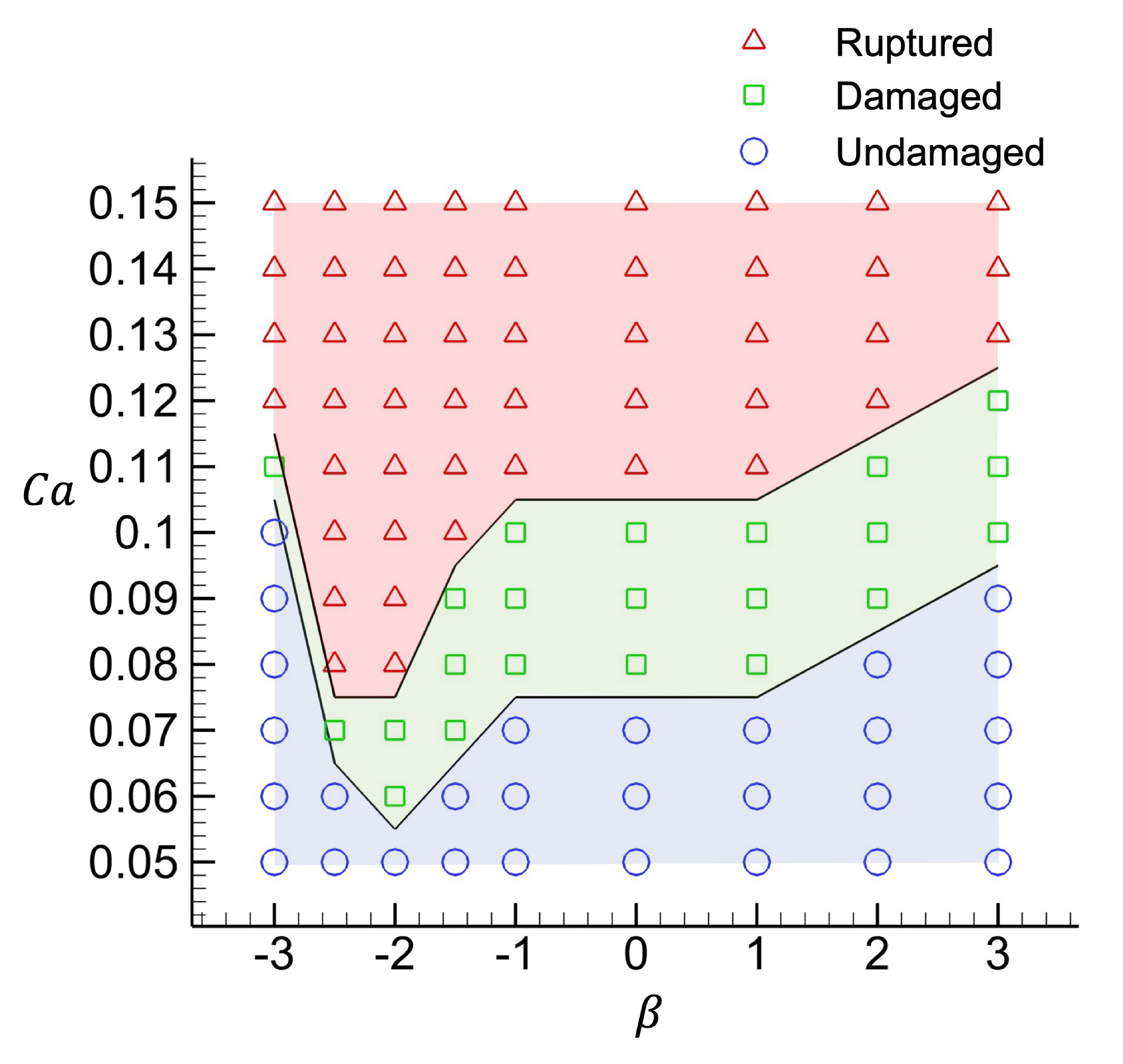
Figure 5. Phase diagram of damage development in $\beta$
and
$\beta$
and $Ca$
space. The initial incidence angle is set to
$Ca$
space. The initial incidence angle is set to $\theta = 30^{\circ }$
.
$\theta = 30^{\circ }$
.
When $Ca$
is less than 0.05, the membrane deformation is sufficiently small that the strain energy does not reach the threshold for onset of brittle damage for all
$Ca$
is less than 0.05, the membrane deformation is sufficiently small that the strain energy does not reach the threshold for onset of brittle damage for all $\beta$
. In regimes where
$\beta$
. In regimes where $Ca$
is greater than 0.05, the damage state depends on the swimming mode
$Ca$
is greater than 0.05, the damage state depends on the swimming mode $\beta$
. In the case of a strong pusher-type squirmer, i.e. in the
$\beta$
. In the case of a strong pusher-type squirmer, i.e. in the $\beta \lt -2$
regime, the squirmer tends to swim along with the membrane surface, and the undamaged regime expands with
$\beta \lt -2$
regime, the squirmer tends to swim along with the membrane surface, and the undamaged regime expands with $|\beta |$
. In this regime, the critical capillary number for membrane rupture
$|\beta |$
. In this regime, the critical capillary number for membrane rupture $Ca_0$
is close to the
$Ca_0$
is close to the $Ca$
value at which brittle damage begins, and the undamaged and rupture states are close together. However, in the case of a weak pusher-type squirmer (
$Ca$
value at which brittle damage begins, and the undamaged and rupture states are close together. However, in the case of a weak pusher-type squirmer ( $-2\leqslant \beta \lt -1$
), the squirmer tends to swim towards the membrane surface, and the membrane is susceptible to damage from the recirculating flow in front of the squirmer (cf. figure 1
b), with
$-2\leqslant \beta \lt -1$
), the squirmer tends to swim towards the membrane surface, and the membrane is susceptible to damage from the recirculating flow in front of the squirmer (cf. figure 1
b), with $Ca_0$
reaching a minimum value at
$Ca_0$
reaching a minimum value at $\beta = -2$
, where the swimming direction undergoes a transition from being aligned with the surface to being oriented against it. In regimes where
$\beta = -2$
, where the swimming direction undergoes a transition from being aligned with the surface to being oriented against it. In regimes where $\beta \geqslant -1$
, in particular where
$\beta \geqslant -1$
, in particular where $\beta \geqslant 1$
, the undamaged regime tends to widen as
$\beta \geqslant 1$
, the undamaged regime tends to widen as $\beta$
increases. In the
$\beta$
increases. In the $-1 \lt \beta \lt 1$
regime, the flow generated by the squirmer is relatively smooth and weak, and all squirmers in this regime tend to swim towards the membrane surface, thus the critical capillary numbers become the same. Conversely, in the
$-1 \lt \beta \lt 1$
regime, the flow generated by the squirmer is relatively smooth and weak, and all squirmers in this regime tend to swim towards the membrane surface, thus the critical capillary numbers become the same. Conversely, in the $\beta \gt 1$
regime, the flow in front of the squirmer tends to draw the capsule membrane close to the squirmer, thereby cancelling out a part of the deformation towards outside, and thus expanding the undamaged region as
$\beta \gt 1$
regime, the flow in front of the squirmer tends to draw the capsule membrane close to the squirmer, thereby cancelling out a part of the deformation towards outside, and thus expanding the undamaged region as $\beta$
increases.
$\beta$
increases.
3.5. Effect of incidence angle
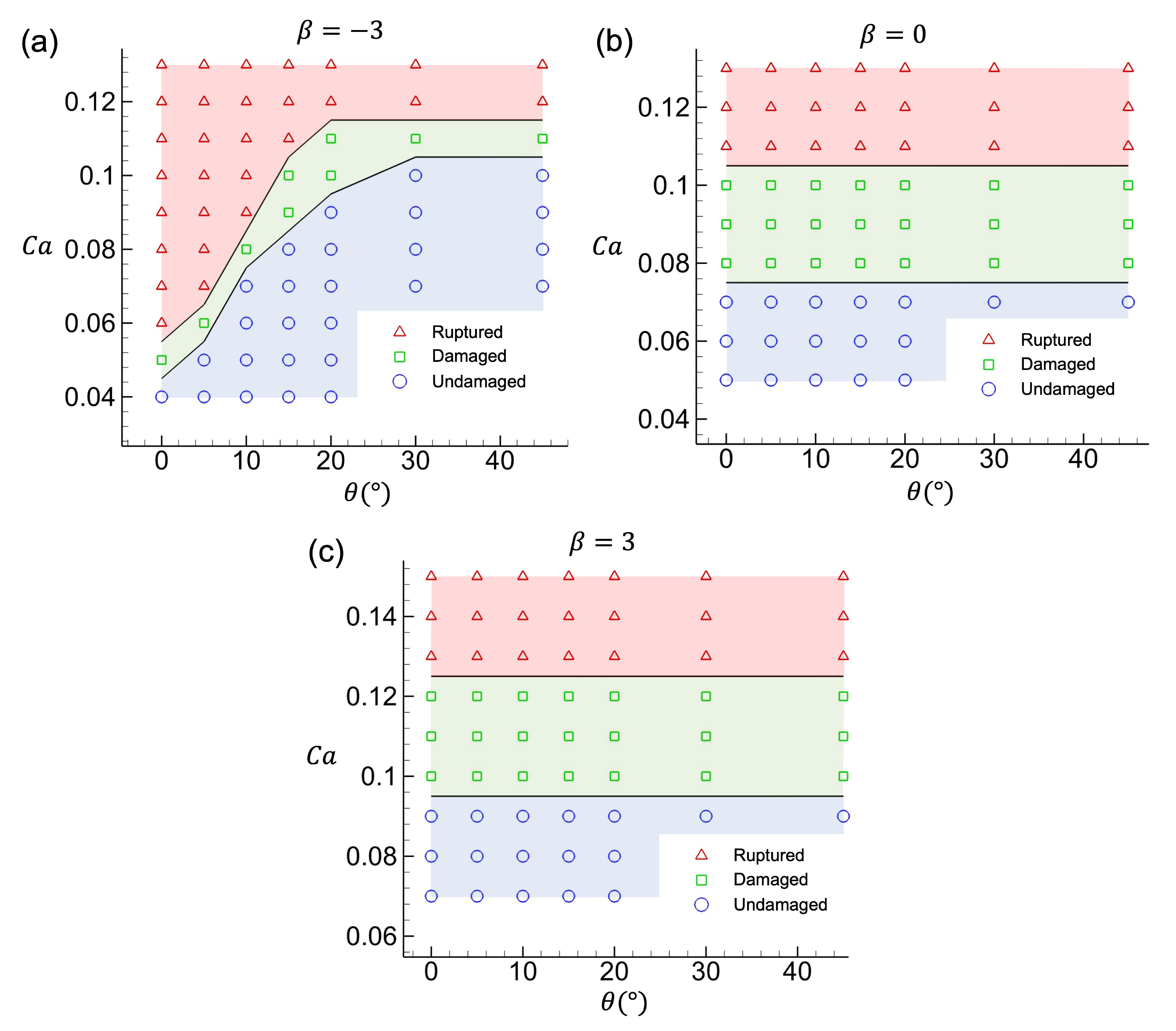
Figure 6. Effect of the initial incidence angle $\theta$
: capsule enclosing (a) a pusher-type squirmer (
$\theta$
: capsule enclosing (a) a pusher-type squirmer ( $\beta = -3$
), (b) a neutral-type squirmer (
$\beta = -3$
), (b) a neutral-type squirmer ( $\beta = 0$
), and (c) a puller-type squirmer (
$\beta = 0$
), and (c) a puller-type squirmer ( $\beta = 3$
).
$\beta = 3$
).
In the following investigation, the influence of the incidence angle $\theta$
is examined by varying the initial position of the squirmer
$\theta$
is examined by varying the initial position of the squirmer $y$
(see figure 1
a). The swimming mode
$y$
(see figure 1
a). The swimming mode $\beta$
is set to
$\beta$
is set to $\beta =-3,0,3$
, and the results are shown in figure 6.
$\beta =-3,0,3$
, and the results are shown in figure 6.
When $\beta =-3$
, the critical capillary number increases with the incidence angle (see figure 6
a), indicating that the capsule becomes harder to damage. When the angle of incidence is large, the initial swimming direction of the squirmer is almost tangential to the capsule surface, and it swims stably along the surface (see supplementary movie 5). Conversely, when the angle of incidence is small, the initial swimming direction is almost perpendicular to the capsule surface, resulting in severe deformation of the capsule (see supplementary movie 4). This makes the capsule more susceptible to damage.
$\beta =-3$
, the critical capillary number increases with the incidence angle (see figure 6
a), indicating that the capsule becomes harder to damage. When the angle of incidence is large, the initial swimming direction of the squirmer is almost tangential to the capsule surface, and it swims stably along the surface (see supplementary movie 5). Conversely, when the angle of incidence is small, the initial swimming direction is almost perpendicular to the capsule surface, resulting in severe deformation of the capsule (see supplementary movie 4). This makes the capsule more susceptible to damage.
When $\beta =0$
and 3, the critical capillary number is found to be unaffected by the incidence angle (figure 1
b,c), indicating that the occurrence of brittle damage is independent of the initial condition. In the case of a puller-type squirmer or a neutral-type squirmer, the squirmer tends to swim perpendicular to the capsule surface. Therefore, in the present study, the direction of swimming near the membrane is determined regardless of the initial conditions, and as a result,
$\beta =0$
and 3, the critical capillary number is found to be unaffected by the incidence angle (figure 1
b,c), indicating that the occurrence of brittle damage is independent of the initial condition. In the case of a puller-type squirmer or a neutral-type squirmer, the squirmer tends to swim perpendicular to the capsule surface. Therefore, in the present study, the direction of swimming near the membrane is determined regardless of the initial conditions, and as a result, $\theta$
dependence cannot be observed (see supplementary movies 6 and 7).
$\theta$
dependence cannot be observed (see supplementary movies 6 and 7).
4. Rupture control by external magnetic torque
Then comes the question, can we manipulate the damage of a capsule? Here, we consider using an external magnetic field to manipulate damage by controlling the swimming direction of the squirmer. We assume that the artificial squirmer is composed of a magnetic material with uniform magnetisation $\boldsymbol{M}$
, and the density of the magnetic field is considered as
$\boldsymbol{M}$
, and the density of the magnetic field is considered as $\boldsymbol{B}$
. The magnetic torque exerted on the squirmer is then defined in the equation (Abbott, Diller & Petruska Reference Abbott, Diller and Petruska2020)
$\boldsymbol{B}$
. The magnetic torque exerted on the squirmer is then defined in the equation (Abbott, Diller & Petruska Reference Abbott, Diller and Petruska2020)
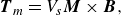 \begin{equation} \boldsymbol{T}_{m}=V_s\boldsymbol{M} \times \boldsymbol{B}, \end{equation}
where $V_s$
corresponds to the volume of the squirmer. We also assume that the orientation vector
$V_s$
corresponds to the volume of the squirmer. We also assume that the orientation vector $\boldsymbol{e}$
of the squirmer is the same as the magnetisation, and the magnetic field
$\boldsymbol{e}$
of the squirmer is the same as the magnetisation, and the magnetic field $\boldsymbol{B}$
is in the same plane as the swimming direction. Thus the magnetic torque exerted on the squirmer can be written as
$\boldsymbol{B}$
is in the same plane as the swimming direction. Thus the magnetic torque exerted on the squirmer can be written as
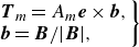 \begin{equation} \left.\begin{array}{l}\boldsymbol{T}_{m}=A_m\boldsymbol{e} \times \boldsymbol{b},\\ \boldsymbol{b}=\boldsymbol{B}/|\boldsymbol{B}|, \end{array}\right\}\end{equation}
where $A_m$
is the amplitude of the magnetic torque, and
$A_m$
is the amplitude of the magnetic torque, and $\boldsymbol{b}$
is the unit vector of the magnetic field
$\boldsymbol{b}$
is the unit vector of the magnetic field $\boldsymbol{B}$
.
$\boldsymbol{B}$
.
4.1. Breaking a harder capsule with a static magnetic field
First, drug release is assumed, then an external magnetic field is applied to rupture the elastically deforming capsule membrane. A pusher-type squirmer ( $\beta = -3$
) is used, and a static magnetic field is considered for the external magnetic field,
$\beta = -3$
) is used, and a static magnetic field is considered for the external magnetic field, $\boldsymbol{b}=(\sqrt {3},1,0)/2$
.
$\boldsymbol{b}=(\sqrt {3},1,0)/2$
.
The capillary number is set to $Ca=0.07$
to correspond to a brittle damage-free regime with stable elastic deformation except for initial defects with initial incidence angle less than
$Ca=0.07$
to correspond to a brittle damage-free regime with stable elastic deformation except for initial defects with initial incidence angle less than $10^ \circ$
.
$10^ \circ$
.
The magnetic torque activates at the dimensionless time $tU_0/a_s =15.0$
, and its amplitude is set to
$tU_0/a_s =15.0$
, and its amplitude is set to $A_m/\unicode{x03BC} a_s^2U_0 = 30$
. Before the activation of the magnetic torque, the squirmer swims along with the surface. However, after the activation of the magnetic field, the squirmer’s movement is directed towards the direction of the magnetic field
$A_m/\unicode{x03BC} a_s^2U_0 = 30$
. Before the activation of the magnetic torque, the squirmer swims along with the surface. However, after the activation of the magnetic field, the squirmer’s movement is directed towards the direction of the magnetic field $\boldsymbol{b}$
due to the magnetic torque, as shown in figure 7 and supplementary movie 8. The second incident angle is smaller, and is accompanied by deformation of the rupture regime. This results in the eventual rupture of the membrane.
$\boldsymbol{b}$
due to the magnetic torque, as shown in figure 7 and supplementary movie 8. The second incident angle is smaller, and is accompanied by deformation of the rupture regime. This results in the eventual rupture of the membrane.
We then investigate the effect of $A_m$
on the critical capillary number. As demonstrated in figure 7(a), the critical capillary number undergoes a substantial decrease due to the influence of the external magnetic torque
$A_m$
on the critical capillary number. As demonstrated in figure 7(a), the critical capillary number undergoes a substantial decrease due to the influence of the external magnetic torque $A_m$
. The findings suggest that the rupture of the membrane can be controlled by the squirmer through the application of a sufficiently large external torque.
$A_m$
. The findings suggest that the rupture of the membrane can be controlled by the squirmer through the application of a sufficiently large external torque.
Figure 7. Rupture of the capsule with a pusher-type squirmer inside controlled ( $\beta = -3$
) by a constant external magnetic torque. The normalised magnetic field vector is set to
$\beta = -3$
) by a constant external magnetic torque. The normalised magnetic field vector is set to $\boldsymbol{b} = (\sqrt {3},1,0)/2$
, and the initial incidence angle is set to
$\boldsymbol{b} = (\sqrt {3},1,0)/2$
, and the initial incidence angle is set to $\theta = 30^{\circ }$
. (a) Effect of the amplitude of external magnetic torque
$\theta = 30^{\circ }$
. (a) Effect of the amplitude of external magnetic torque $A_m$
. (b) Behaviour of the pusher-type squirmer until the membrane becomes ruptured. Magnetic torque is applied at
$A_m$
. (b) Behaviour of the pusher-type squirmer until the membrane becomes ruptured. Magnetic torque is applied at $tU_0/a_s = 15$
(indicated by the cross) to control the swimming direction of the squirmer. By applying the magnetic torque with amplitude
$tU_0/a_s = 15$
(indicated by the cross) to control the swimming direction of the squirmer. By applying the magnetic torque with amplitude $A_m/\unicode{x03BC} a_s^2U_0 = 30$
, the stable circular swimming of the inside squirmer changes to a one-directional swimming, which allows the squirmer to break the capsule (
$A_m/\unicode{x03BC} a_s^2U_0 = 30$
, the stable circular swimming of the inside squirmer changes to a one-directional swimming, which allows the squirmer to break the capsule ( $Ca$
is set to 0.07).
$Ca$
is set to 0.07).
4.2. Preserving a capsule by a rotational magnetic field
Figure 8. Rupture of the capsule with a pusher-type squirmer inside controlled by a rotating magnetic field; $\beta = -3$
,
$\beta = -3$
, $Ca = 0.15$
and
$Ca = 0.15$
and $\theta = 30^{\circ }$
for all cases. (a) Phase diagram in
$\theta = 30^{\circ }$
for all cases. (a) Phase diagram in $A_m$
and
$A_m$
and $\omega _m$
space. (b–g) Effects of the angular velocity on the swimming of the squirmer:
$\omega _m$
space. (b–g) Effects of the angular velocity on the swimming of the squirmer: $\omega _ma_s/U_0 = 0.2, 1.0,2.0, 2.2,5.0,50.0$
, respectively, while the amplitude is set to
$\omega _ma_s/U_0 = 0.2, 1.0,2.0, 2.2,5.0,50.0$
, respectively, while the amplitude is set to $A_m/\unicode{x03BC} a_s^2U_0 = 40$
for all cases. The black line indicates the swimming trajectory of the squirmer, and the blue and the red arrows correspond to the swimming direction
$A_m/\unicode{x03BC} a_s^2U_0 = 40$
for all cases. The black line indicates the swimming trajectory of the squirmer, and the blue and the red arrows correspond to the swimming direction $\boldsymbol{e}$
and the normalised magnetic field vector
$\boldsymbol{e}$
and the normalised magnetic field vector $\boldsymbol{b}$
, respectively.
$\boldsymbol{b}$
, respectively.
Next, the potential of a rotating magnetic field in preventing the rupture of a softer capsule is explored. A pusher-type squirmer ( $\beta = -3$
) is employed as the internal swimmer. Under these conditions, the capsule remains in the ruptured regime in the absence of magnetic torque. The rotating magnetic field is defined as
$\beta = -3$
) is employed as the internal swimmer. Under these conditions, the capsule remains in the ruptured regime in the absence of magnetic torque. The rotating magnetic field is defined as $\boldsymbol{b}=(\cos \omega _m t,-\sin \omega _m t,0)$
, where
$\boldsymbol{b}=(\cos \omega _m t,-\sin \omega _m t,0)$
, where $t$
is time. The magnitude of the torque is set to
$t$
is time. The magnitude of the torque is set to $A_m/\unicode{x03BC} a_s^2U_0 = 40$
, and the angular velocity
$A_m/\unicode{x03BC} a_s^2U_0 = 40$
, and the angular velocity $\omega _m$
is parametrised (see figure 8).
$\omega _m$
is parametrised (see figure 8).
When the angular velocity is sufficiently small, e.g. $\omega _ma_s/U_0 = 0.2$
in figure 8(b), the magnetic field changes too slowly to make the swimmer move away from the membrane. This condition is analogous to the absence of a magnetic field, and the capsule reaches a rupture state (see supplementary movie 9). When the angular velocity of the magnetic field is comparable to the swimming speed (
$\omega _ma_s/U_0 = 0.2$
in figure 8(b), the magnetic field changes too slowly to make the swimmer move away from the membrane. This condition is analogous to the absence of a magnetic field, and the capsule reaches a rupture state (see supplementary movie 9). When the angular velocity of the magnetic field is comparable to the swimming speed ( $0.2 \lt \omega _ma_s/U_0 \leqslant 1.5$
), the squirmer traces a circular orbit of its radius, and the interaction with the membrane also becomes weak. Therefore, the capsule membrane is preserved (cf. figure 8(c) and supplementary movie 10). However, when the angular velocity is approximately
$0.2 \lt \omega _ma_s/U_0 \leqslant 1.5$
), the squirmer traces a circular orbit of its radius, and the interaction with the membrane also becomes weak. Therefore, the capsule membrane is preserved (cf. figure 8(c) and supplementary movie 10). However, when the angular velocity is approximately $1.5 \lt \omega _ma_s/U_0 \leqslant 2$
, the swimming path becomes unstable, and the increased frequency of near-field interactions between the capsule and the squirmer tends to increase the susceptibility to rupture (cf. figure 8(d) and supplementary movie 11). Then in the regime with larger
$1.5 \lt \omega _ma_s/U_0 \leqslant 2$
, the swimming path becomes unstable, and the increased frequency of near-field interactions between the capsule and the squirmer tends to increase the susceptibility to rupture (cf. figure 8(d) and supplementary movie 11). Then in the regime with larger $\omega _m$
(
$\omega _m$
( $2 \lt \omega _ma_s/U_0 \leqslant 10$
), the angular velocity of the magnetic field gradually becomes dominant in relation to the angular velocity of swimming (
$2 \lt \omega _ma_s/U_0 \leqslant 10$
), the angular velocity of the magnetic field gradually becomes dominant in relation to the angular velocity of swimming ( $\omega _m \gt |\boldsymbol{\Omega }|$
), and the swimming trajectory again approaches a smooth circular path (cf. figure 8(e,f ) and supplementary movies 12 and 13). However, with extremely large angular velocities, e.g.
$\omega _m \gt |\boldsymbol{\Omega }|$
), and the swimming trajectory again approaches a smooth circular path (cf. figure 8(e,f ) and supplementary movies 12 and 13). However, with extremely large angular velocities, e.g. $\omega _ma_s/U_0=50$
in figure 8(g), the magnetic field undergoes such rapid changes that the swimmer is unable to maintain its course. Consequently, the motion of the squirmer reverts to a state of sufficiently small angular velocity, resulting in the membrane reaching a rupture state (see supplementary movie 14).
$\omega _ma_s/U_0=50$
in figure 8(g), the magnetic field undergoes such rapid changes that the swimmer is unable to maintain its course. Consequently, the motion of the squirmer reverts to a state of sufficiently small angular velocity, resulting in the membrane reaching a rupture state (see supplementary movie 14).
The phase diagram of the membrane damage due to torque magnitude $A_m$
and angular velocity
$A_m$
and angular velocity $\omega _s$
is summarised in figure 8(a). Evidence suggests that there is indeed a damage-free region, indicating the potential for utilising the rotating magnetic field as a soft capsule transport technique.
$\omega _s$
is summarised in figure 8(a). Evidence suggests that there is indeed a damage-free region, indicating the potential for utilising the rotating magnetic field as a soft capsule transport technique.
5. Conclusion
In this study, we proposed a capsule enclosing a microswimmer, and focused on the damage behaviour of the capsule membrane. In the present simulation, three distinct capsule states were obtained: namely, the undamaged state, the damaged state, and the rupture state.
It is important to note that the repulsive force determines the minimum distance between the squirmer and the capsule membrane, thus it has the capacity to affect the result quantitatively. In this study, the minimum repulsive force required for a mesh-size separation between the squirmer and the capsule membrane was determined. However, for repulsive forces below this level, the calculations become unstable due to a lack of resolution in expressing the lubrication flow.
In the context of the fixed swimming mode, an increase in $Ca$
has been observed to result in capsules undergoing greater deformation, attributable to hydrodynamic interaction. A comparison of these findings with those of a previous study (Grandmaison et al. Reference Grandmaison, Brancherie and Salsac2021) reveals a parallel in the damage development process of the capsules. Specifically, the damage variable exhibits a steady increase below
$Ca$
has been observed to result in capsules undergoing greater deformation, attributable to hydrodynamic interaction. A comparison of these findings with those of a previous study (Grandmaison et al. Reference Grandmaison, Brancherie and Salsac2021) reveals a parallel in the damage development process of the capsules. Specifically, the damage variable exhibits a steady increase below $d \approx 0.2$
, and subsequently experiences a steep rise until reaching
$d \approx 0.2$
, and subsequently experiences a steep rise until reaching $d=1$
. Meanwhile, we find that our capsule can be damaged more easily (with a smaller
$d=1$
. Meanwhile, we find that our capsule can be damaged more easily (with a smaller $Ca_0$
). The underlying cause of these discrepancies can be attributed to the hydrodynamic interaction. Grandmaison et al. (Reference Grandmaison, Brancherie and Salsac2021) made their capsule deformed by simple shear flow, a moderate interaction affecting the whole capsule, while we use an inside microswimmer, generating a strong interaction near the microswimmer. Also, comparing our results with Leopércio et al. (Reference Leopércio, Michelon and Carvalho2021), we find the same trend of damage: a capsule with a larger capillary number
$Ca_0$
). The underlying cause of these discrepancies can be attributed to the hydrodynamic interaction. Grandmaison et al. (Reference Grandmaison, Brancherie and Salsac2021) made their capsule deformed by simple shear flow, a moderate interaction affecting the whole capsule, while we use an inside microswimmer, generating a strong interaction near the microswimmer. Also, comparing our results with Leopércio et al. (Reference Leopércio, Michelon and Carvalho2021), we find the same trend of damage: a capsule with a larger capillary number $Ca$
and larger deformation can be damaged more easily.
$Ca$
and larger deformation can be damaged more easily.
When $Ca$
is held constant, the difference in the swimming mode
$Ca$
is held constant, the difference in the swimming mode $\beta$
can be categorised into two distinct behaviours of the inside squirmer: sliding along the capsule surface (
$\beta$
can be categorised into two distinct behaviours of the inside squirmer: sliding along the capsule surface ( $\beta \lt -2$
), and swimming towards the capsule surface (
$\beta \lt -2$
), and swimming towards the capsule surface ( $\beta \geqslant -2$
). According to previous research (Ishikawa Reference Ishikawa2019), a pusher-type squirmer (
$\beta \geqslant -2$
). According to previous research (Ishikawa Reference Ishikawa2019), a pusher-type squirmer ( $\beta \lt 0$
) tends to turn away from the free surface, while a neutral-type squirmer (
$\beta \lt 0$
) tends to turn away from the free surface, while a neutral-type squirmer ( $\beta = 0$
) or a puller-type squirmer (
$\beta = 0$
) or a puller-type squirmer ( $\beta \gt 0$
) tends to swim towards the free surface. In our results, a strong pusher-type squirmer (
$\beta \gt 0$
) tends to swim towards the free surface. In our results, a strong pusher-type squirmer ( $\beta \lt -2$
), a neutral-type squirmer (
$\beta \lt -2$
), a neutral-type squirmer ( $\beta = 0$
) and a puller-type squirmer (
$\beta = 0$
) and a puller-type squirmer ( $\beta \gt 0$
) have the same motion with Ishikawa (Reference Ishikawa2019), while a weak pusher-type squirmer (
$\beta \gt 0$
) have the same motion with Ishikawa (Reference Ishikawa2019), while a weak pusher-type squirmer ( $ -2 \leqslant \beta \lt 0$
) also swims towards the capsule surface. The reason for this phenomenon is attributed to the soft capsule surface. When a weak pusher-type squirmer first encounters the capsule surface, the torque received is not strong enough to make it completely turn away from the capsule surface, and it is then surrounded by the capsule membrane because of deformation. Also, in the results of Ishikawa (Reference Ishikawa2019), a pusher-type squirmer receives larger rotational torque when swimming parallel to the free surface than when swimming towards the surface. In our results, therefore, a weak pusher-type squirmer receives larger torque from its side than from its front, and becomes no longer able to turn away from the capsule surface. In terms of damage of the capsule, in the situation
$ -2 \leqslant \beta \lt 0$
) also swims towards the capsule surface. The reason for this phenomenon is attributed to the soft capsule surface. When a weak pusher-type squirmer first encounters the capsule surface, the torque received is not strong enough to make it completely turn away from the capsule surface, and it is then surrounded by the capsule membrane because of deformation. Also, in the results of Ishikawa (Reference Ishikawa2019), a pusher-type squirmer receives larger rotational torque when swimming parallel to the free surface than when swimming towards the surface. In our results, therefore, a weak pusher-type squirmer receives larger torque from its side than from its front, and becomes no longer able to turn away from the capsule surface. In terms of damage of the capsule, in the situation $\beta \lt -2$
, a squirmer with smaller
$\beta \lt -2$
, a squirmer with smaller $\beta$
receives a larger rotational torque to make itself turn away from the capsule surface. This results in a weaker hydrodynamic interaction with the capsule, and an increased threshold
$\beta$
receives a larger rotational torque to make itself turn away from the capsule surface. This results in a weaker hydrodynamic interaction with the capsule, and an increased threshold $Ca$
. But in the situation
$Ca$
. But in the situation $\beta \geqslant -2$
, all kinds of squirmers swim towards the capsule surface. As
$\beta \geqslant -2$
, all kinds of squirmers swim towards the capsule surface. As $\beta$
increases, the deformation at the capsule surface is gradually annulled by the hydrodynamic interaction, and the threshold
$\beta$
increases, the deformation at the capsule surface is gradually annulled by the hydrodynamic interaction, and the threshold $Ca$
also increases. In terms of damage manipulation, it has been found that the application of a static magnetic torque to the microswimmer results in the rupture state being attained at a lower
$Ca$
also increases. In terms of damage manipulation, it has been found that the application of a static magnetic torque to the microswimmer results in the rupture state being attained at a lower $Ca=0.07$
as compared to the value
$Ca=0.07$
as compared to the value $Ca=0.12$
observed in the absence of a static torque. Conversely, when a rotational magnetic torque is applied to the microswimmer, it is observed that the capsule can be maintained in an undamaged state at a high capillary number (
$Ca=0.12$
observed in the absence of a static torque. Conversely, when a rotational magnetic torque is applied to the microswimmer, it is observed that the capsule can be maintained in an undamaged state at a high capillary number ( $Ca=0.15$
) if the appropriate rotational magnetic field is applied (cf. figure 8).
$Ca=0.15$
) if the appropriate rotational magnetic field is applied (cf. figure 8).
When considering a real microswimmer, a Janus particle constitutes a viable candidate. A Janus particle is composed of two distinct materials, and can be propelled by a concentration difference, electrical or thermal conductivity of the surrounding fluid. For instance, a metal rod made of platinum and gold can be propelled by its self-electrophoresis (Moran & Posner Reference Moran and Posner2017). When such a metal rod is immersed in hydrogen peroxide, peroxide oxidation occurs at the platinum end, and peroxide reduction occurs at the gold end. The oxidation reaction produces protons, while the reduction reaction consumes them, thereby establishing a proton concentration gradient via the electrochemical reactions occurring on the nanomotor surface. The ions drag fluid in the same direction, leading to relative motion between the particle and the fluid such that the motor moves with the platinum end directed forwards. In the mathematical analysis of phoretic microswimmers, the fluid domain is commonly divided into two regions: the bulk region, and the interfacial region surrounding the particle (Moran & Posner Reference Moran and Posner2017). Assuming that phoretic effects are confined to the thin interfacial region, such effects can be represented as surface slip velocities. Therefore, a phoretic microswimmer can be modelled as a squirmer. Control of such microswimmers can be achieved through magnetism by substituting one metal with a magnetic metal, such as Janus particles of a gold–nickel alloy, as demonstrated in the study by Wang et al. (Reference Wang, Hernandez, Bartlett, Bingham, Kline, Sen and Mallouk2006).
In the context of the capsule, previous research focused on the vesicle membrane, as evidenced by the work of Nagard et al. (Reference Le Nagard, Brown, Dawson, Martinez, Poon and Staykova2022), who put several inside giant unilamellar vesicles. The vesicle membrane deformed enormously due to bacterial movement, yet it remained intact, suggesting that the lipid molecules that make up the vesicle membrane may flow in response to deformation, thereby preventing rupture. However, the fluidity of vesicle membranes poses challenges in terms of control over membrane breakdown. In contrast, a capsule does not fluidise because it has an elastic membrane, and brittle fracture occurs when local deformation exceeds a threshold value. We therefore focus on the control of substance release by an elastic capsule membrane rather than by a vesicle membrane.
In a previous study, for instance, a capsule was fabricated using polysiloxane, which possesses elastic modulus approximately $G_s\sim 5 \times 10^{-5}\ \rm N\ m^-{^1}$
(Feinberg, Funderburgh & Simko Reference Feinberg, Funderburgh and Simko2015). Another example can be a capsule made by a ghost cell of a red blood cell membrane, whose elastic modulus is
$G_s\sim 5 \times 10^{-5}\ \rm N\ m^-{^1}$
(Feinberg, Funderburgh & Simko Reference Feinberg, Funderburgh and Simko2015). Another example can be a capsule made by a ghost cell of a red blood cell membrane, whose elastic modulus is $G_s\sim 10^{-6}\ \rm N\ m^-{^1}$
, as cited in Omori et al. (Reference Omori, Imai, Yamaguchi and Ishikawa2012). Examples of squirmers include Janus particles and swimming microorganisms. Recent studies have revealed that gold–platinum type Janus particles exhibit swimming velocity 25
$G_s\sim 10^{-6}\ \rm N\ m^-{^1}$
, as cited in Omori et al. (Reference Omori, Imai, Yamaguchi and Ishikawa2012). Examples of squirmers include Janus particles and swimming microorganisms. Recent studies have revealed that gold–platinum type Janus particles exhibit swimming velocity 25 $\unicode{x03BC} \rm m\ s^-{^1}$
(Moran & Posner Reference Moran and Posner2017), while bacteria E. coli have been documented to swim at velocity 1
$\unicode{x03BC} \rm m\ s^-{^1}$
(Moran & Posner Reference Moran and Posner2017), while bacteria E. coli have been documented to swim at velocity 1 $\unicode{x03BC} \rm m\ s^-{^1}$
(Ishikawa Reference Ishikawa2024b
). Additionally, microalgae Volvox have been recorded to swim at velocity 250
$\unicode{x03BC} \rm m\ s^-{^1}$
(Ishikawa Reference Ishikawa2024b
). Additionally, microalgae Volvox have been recorded to swim at velocity 250 $\unicode{x03BC} \rm m\ s^-{^1}$
(Drescher et al. Reference Drescher, Leptos, Tuval, Ishikawa, Pedley and Goldstein2009), and ciliate Paramecium have been recorded to swim at velocity 1
$\unicode{x03BC} \rm m\ s^-{^1}$
(Drescher et al. Reference Drescher, Leptos, Tuval, Ishikawa, Pedley and Goldstein2009), and ciliate Paramecium have been recorded to swim at velocity 1 $\rm mm\ s^-{^1}$
(Ishikawa Reference Ishikawa2024b
). Assuming the surrounding fluid to be oleic acid, whose viscosity is approximately
$\rm mm\ s^-{^1}$
(Ishikawa Reference Ishikawa2024b
). Assuming the surrounding fluid to be oleic acid, whose viscosity is approximately $\unicode{x03BC} \sim 5 \times 10^{-2}\ \text{Pa s}$
(Sagdeev et al. Reference Sagdeev, Gabitov, Isyanov, Khairutdinov, Farakhov, Zaripov and Abdulagatov2019), the critical speed that can break the polysiloxane capsule is
$\unicode{x03BC} \sim 5 \times 10^{-2}\ \text{Pa s}$
(Sagdeev et al. Reference Sagdeev, Gabitov, Isyanov, Khairutdinov, Farakhov, Zaripov and Abdulagatov2019), the critical speed that can break the polysiloxane capsule is $U \sim 100\ \unicode{x03BC} \rm m\ s^-{^1}$
. However, if the capsule is composed of a ghost cell derived from a red blood cell membrane, then the critical speed required for capsule rupture decreases to approximately
$U \sim 100\ \unicode{x03BC} \rm m\ s^-{^1}$
. However, if the capsule is composed of a ghost cell derived from a red blood cell membrane, then the critical speed required for capsule rupture decreases to approximately $U \sim 2\ \unicode{x03BC} \rm m\ s^-{^1}$
. It is then considered that both Janus swimmers and microorganisms can disrupt these capsules from the inside.
$U \sim 2\ \unicode{x03BC} \rm m\ s^-{^1}$
. It is then considered that both Janus swimmers and microorganisms can disrupt these capsules from the inside.
The findings of this study demonstrate that the impairment of the capsule membrane can be regulated by modifying its capillary number, as well as the swimming mode and incidence angle of the inside microswimmer. Furthermore, the implementation of a magnetic field enables the modulation of the internal microswimmer’s trajectory, thereby affecting the integrity of the capsule membrane. It is imperative to comprehend the interplay between the damage to the capsule membrane and the motion of the internal microswimmer, as evidenced by these findings. Furthermore, they establish the basis for potential applications, including controlled drug release.
Supplementary movies
Supplementary movies are available at https://doi.org/10.1017/jfm.2025.10238.
Acknowledgements
This work was supported by JST SPRING (grant no. JPMJSP2114), JST PRESTO (grant no. J210002385) and JSPS KAKENHI (grant nos 24H01458, 21H04999 and 21H05308).
Declaration of interests
The authors report no conflict of interest.


 Open access