


1. Introduction
Vortex-ring dynamics is one of the most extensively studied topics in the area of fluid dynamics because vortices are closely associated with a wide range of natural phenomena and engineering applications. The former would include the swimming mechanisms of aquatic animals (Alben et al. Reference Alben, Miller and Peng2013; Maertens et al. Reference Maertens, Gao and Triantafyllou2017) and vortex rings produced by the left ventricles of human hearts (Le & Sotiropoulos Reference Le and Sotiropoulos2012; Töger et al. Reference Töger, Kanski, Carlsson, Kovács, Söderlind, Arheden and Heiberg2012). As for the latter, one of the most popular vortex ring-based usages would be synthetic jets for flow control (Amitay et al. Reference Amitay, Smith and Glezer1998; Glezer & Amitay Reference Glezer and Amitay2002) as well as heat and mass transfer (Donaldson et al. Reference Donaldson, Snedeker and Margolis1971; Hadžiabdić & Hanjalić Reference Hadžiabdić and Hanjalić2008; Arshad et al. Reference Arshad, Jabbal and Yan2020) purposes. Much effort has been expended looking into vortex-ring interactions with different surfaces as well due to their direct relevance to jet impingement-based heating/cooling techniques.
Earlier work on vortex-ring collisions typically looked at head-on or inclined flat wall-based collisions by circular vortex rings (CVRs), such as those by Walker et al. (Reference Walker, Smith, Cerra and Doligalski1987), Lim (Reference Lim1989), Lim et al. (Reference Lim, Nickels and Chong1991), Orlandi & Verzicco (Reference Orlandi and Verzicco1993), Chu et al. (Reference Chu, Wang and Chang1995), Fabris et al. (Reference Fabris, Liepmann and Marcus1996), Cheng et al. (Reference Cheng, Lou and Luo2010), Couch & Krueger (Reference Couch and Krueger2011), New et al. (Reference New, Shi and Zang2016), Gargan-Shingles (Reference Gargan-Shingles2017) and New et al. (Reference New, Long, Zang and Shi2020). These studies have revealed the expansion of the primary vortex-ring diameter upon collision as well as the formation of secondary vortex rings (SVRs) and tertiary vortex rings. Later on, vortex-ring collisions with more complex geometries have been explored, such as those with porous walls (Hrynuk et al. Reference Hrynuk, Van Luipen and Bohl2012; Naaktgeboren et al. Reference Naaktgeboren, Krueger and Lage2012; Cheng et al. Reference Cheng, Lou and Lim2014), convex and concave surfaces (Allen et al. Reference Allen, Jouanne and Shashikanth2007; New & Zang Reference New and Zang2017; Nguyen et al. Reference Nguyen, Takamure and Uchiyama2019; New et al. Reference New, Gotama and Vevek2021; Ahmed & Erath Reference Ahmed and Erath2023; New et al. Reference New, Xu and Shi2024a,Reference New, Xu and Shib; Xu & New Reference Xu and New2024), coaxial circular apertures (Hu & Peterson Reference Hu and Peterson2021), slip boundaries (Song et al. Reference Song, Bernal and Tryggvason1992; Chu et al. Reference Chu, Wang and Hsieh1993; Ohring & Lugt Reference Ohring and Lugt1996; Zhang et al. Reference Zhang, Shen and Yue1999; Archer et al. Reference Archer, Thomas and Coleman2010; Terrington et al. Reference Terrington, Thompson and Hourigan2024; New et al. Reference New, Yeo, Koh and Long2024c), among others.
The variations in vortex-ring collisions of proceeding studies involve varying the collision surface configurations through changes in their boundary types, orientations or relative positions. Changing the vortex rings themselves beyond Reynolds number, core thickness, turbulence level and their generation remain scarce at this point. This is because it is relatively easier to vary the collision surface configurations than the vortex-ring characteristics. This is especially the case for experiments when the vortex-ring generation set-ups need to be modified and recommissioned. Secondly, it is typically more challenging and timeconsuming to design experimental set-ups that produce well-initialised and highly coherent non-circular vortex rings that exhibit idealised and symmetrical behaviour about the dominant axes. Thirdly, non-circular vortex rings exhibit axis-switching behaviour which complicates the interpretations of the collision flow dynamics substantially. Previously, axisswitching of rectangular/square vortex rings has been documented by Grinstein & DeVore (Reference Grinstein and DeVore1996) and Ghasemi et al. (Reference Ghasemi, Tuna and Li2018), while that of the elliptic vortex rings (EVRs) has been noted by Dhanak & Bernardinis (Reference Dhanak and Bernardinis1981), Oshima et al. (Reference Oshima, Izutsu, Oshima and Hussain1988), Hussain & Husain (Reference Hussain and Husain1989), Cheng et al. (Reference Cheng, Lou and Lim2016) and Li & Hong (Reference Li and Hong2024). These studies have revealed that axis-switching behaviour will not only see the major and minor axes of the non-circular vortex rings interchanging repeatedly, but their filaments undergo regular three-dimensional (3-D) distortions as well. These changes arise from the different induced velocities incurred along the entire vortex filament due to its non-uniform curvature. Thus any non-circular vortex-ring collision will be highly sensitive to its exact axis-switching stage when it occurs.
Non-circular vortex-ring collisions are known to be complicated by the non-uniform interactions between non-circular vortex rings and solid surfaces. From previous studies on vortex rings colliding with inclined walls and convex cylindrical surfaces (Lim Reference Lim1989; New et al. Reference New, Shi and Zang2016; New & Zang Reference New and Zang2017), non-uniform formation and entrainment of SVRs lead to the formation of vortex loops and their pinch-off process. Meanwhile, the non-uniform collisions of vortex pairs with solid surfaces also highlight the important role played by the secondary vortices. In this case, the non-uniformity can be either caused by the instability of primary vortices (Asselin & Williamson Reference Asselin and Williamson2017) or imposed by wavy surfaces (Morris & Williamson Reference Morris and Williamson2020; Nguyen et al. Reference Nguyen, Duong and Duong2024). Non-uniform formation and entrainment of secondary vortices lead to vortex loop formations followed by a pinch-off process that gives rise to vortex ringlets. Due to axis-switching behaviour, interactions between non-circular vortex rings and walls are expected to be non-uniform as well.
Among non-circular vortex-ring geometries, an EVR is considered to be the most interesting one. Firstly, its circumference is curved smoothly throughout, just like a CVR, the only difference is that EVR behaviour is sensitive to its aspect ratio. This will be in contrast to rectangular/square vortex rings possessing abrupt curvature changes due to the sharp corners of the nozzle/orifice where they are generated from. Secondly, its ellipticity is described by the aspect ratio ( $AR$
), which makes it easier to control its exact geometry. Thirdly, there exists much research literature on EVRs that sheds much light on their fundamental flow behaviour without external influences, with their axis-switching phenomenon being one of the most interesting flow aspects. Additionally, the pinch-off process of EVRs has also been studied by O’Farrell & Dabiri (Reference O’Farrell and Dabiri2014). More recently, the collisions between EVRs were explored by Chen et al. (Reference Chen, Wang, Li and Wang2016) and Cheng et al. (Reference Cheng, Lou and Lim2019).
$AR$
), which makes it easier to control its exact geometry. Thirdly, there exists much research literature on EVRs that sheds much light on their fundamental flow behaviour without external influences, with their axis-switching phenomenon being one of the most interesting flow aspects. Additionally, the pinch-off process of EVRs has also been studied by O’Farrell & Dabiri (Reference O’Farrell and Dabiri2014). More recently, the collisions between EVRs were explored by Chen et al. (Reference Chen, Wang, Li and Wang2016) and Cheng et al. (Reference Cheng, Lou and Lim2019).
The collision of EVRs with walls is a rarely explored flow scenario, although Xu et al. (Reference Xu, Fan and Wang2024) recently investigated an elliptic synthetic jet impinging upon a wall numerically. Their simulation results reveal notable differences in the collision outcomes between elliptic and circular synthetic impinging jets, where the former leads to additional arc-shaped vortex structures not observed previously. However, firstly the orifice-to-wall distances used were based on regular multiples of the orifice hydraulic diameter rather than key axis-switching stages. While this approach is appropriate for CVRs, it does not fully reveal the impact of axis-switching behaviour on non-circular vortex-ring collisions more systematically. Secondly, synthetic jets comprise trains of multiple vortex rings and their collisions upon a wall may not reflect the actual behaviour of a single discrete vortex ring colliding with the wall in isolation. The presence of additional vortex rings upstream and downstream of the colliding vortex ring is likely to confer additional flow influences.
Therefore, a more systematic understanding of discrete EVR collisions should take into account the key axis-switching stages at the point of collision, where the separation distances are based on these axis-switching locations. Such a consideration motivates the present experimental study, where a combination of planar laser-induced fluorescence (PLIF) visualisations and time-resolved particleimage velocimetry (TR-PIV) measurements was used to shed light on this matter. Results from these experiments not only inform upon the potentially very different vortex dynamics underpinning collisions based on key axis-switching stages, but also potentially provide more information on the most appropriate separation distance for optimal elliptic jet-based heat transfer purposes.
2. Experimental set-up and procedures
2.1. Experimental set-up and vortex-ring generation
All experiments were conducted in a water tank made of 20mm-thick transparent Plexiglass panels with inner working dimensions of 500 mm (W) $\times$
500 mm (L)
$\times$
500 mm (L) $\times$
500 mm (H), as shown in figure 1. A circular opening in one of the panels allowed a specially designed circular plug to be fitted in flushed with the inner surface, where a machined hollow tube was affixed coaxially to form a flushed orifice. A Teflon-based piston block resided at the back of the hollow tube and was attached to a stiff stainless steel rod-and-block set-up fixed to the carriage of a ball screw-based linear actuator. The linear actuator was driven by a high-torque stepper motor, which in turn was controlled by a motor driver programmed using a computer. Although the water tank is different from that of previous studies (New et al. Reference New, Shi and Zang2016; New & Zang Reference New and Zang2017; New et al. Reference New, Long, Zang and Shi2020), the vortex-ring generation method remains similar to these studies. The EVRs were generated using the classical ‘cylindrical slug’ technique, whereby a slug of water was ejected out of the orifice by the impulsivelystarted piston based on a pre-programmed trapezoidal velocity profile.
$\times$
500 mm (H), as shown in figure 1. A circular opening in one of the panels allowed a specially designed circular plug to be fitted in flushed with the inner surface, where a machined hollow tube was affixed coaxially to form a flushed orifice. A Teflon-based piston block resided at the back of the hollow tube and was attached to a stiff stainless steel rod-and-block set-up fixed to the carriage of a ball screw-based linear actuator. The linear actuator was driven by a high-torque stepper motor, which in turn was controlled by a motor driver programmed using a computer. Although the water tank is different from that of previous studies (New et al. Reference New, Shi and Zang2016; New & Zang Reference New and Zang2017; New et al. Reference New, Long, Zang and Shi2020), the vortex-ring generation method remains similar to these studies. The EVRs were generated using the classical ‘cylindrical slug’ technique, whereby a slug of water was ejected out of the orifice by the impulsivelystarted piston based on a pre-programmed trapezoidal velocity profile.
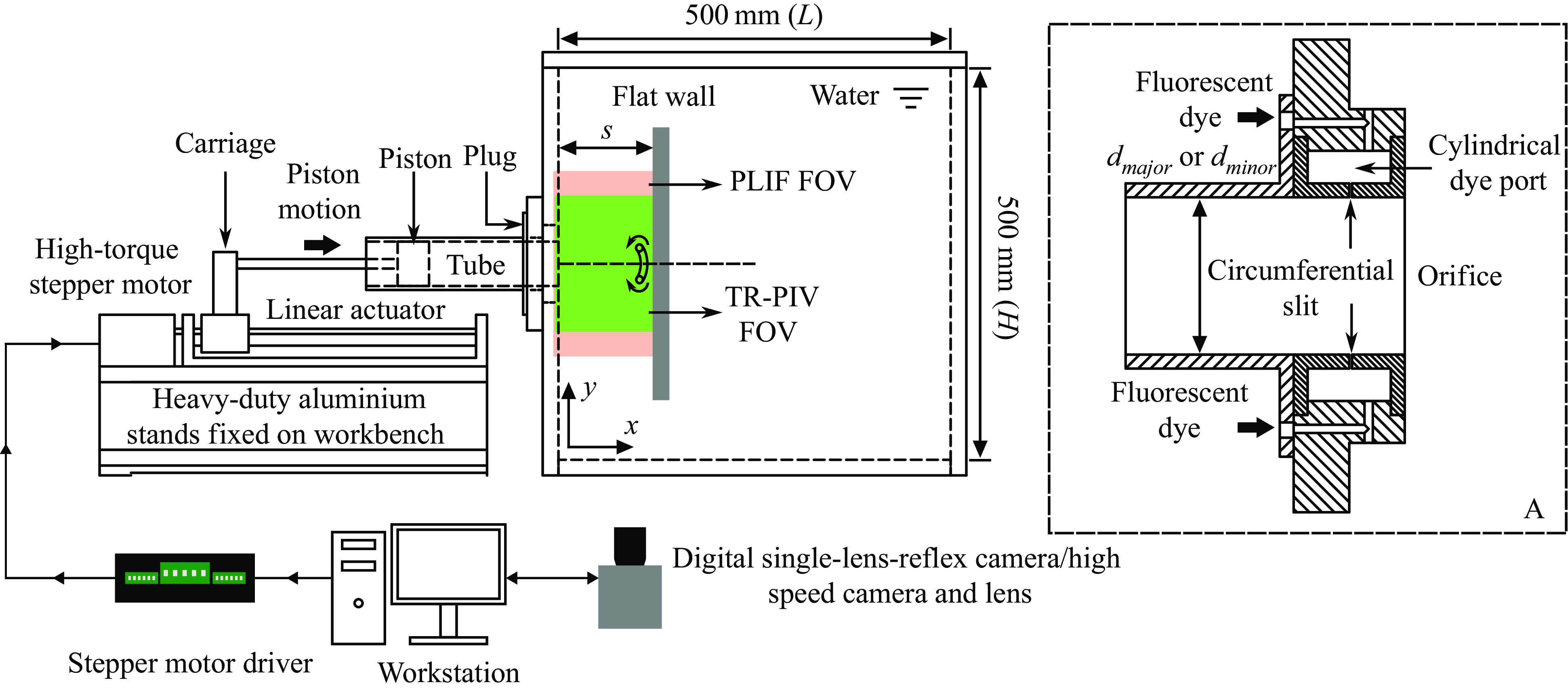
Figure 1. Schematics of the experimental set-up showing how the vortex rings were produced via a ‘cylindrical slug’ approach based on an impulsively driven piston. The FOVs of PLIF visualisations and TR-PIV measurements are included as well. Inset A shows a close-up cross-sectional view of the circumferential dye-release set-up for PLIF visualisations.
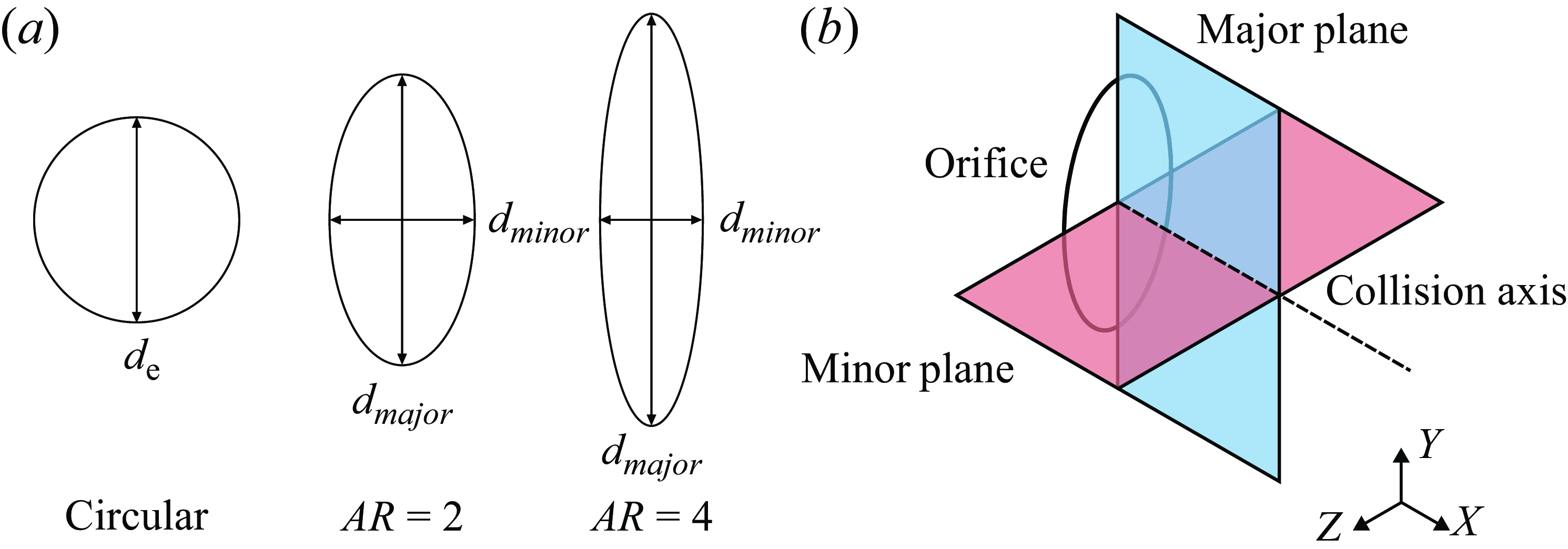
Figure 2. (a) Schematics and nomenclature for the circular, $AR=2$
and 4 elliptic orifices used in the present study, and (b) major and minor planes used for the PLIF visualisations and TR-PIV measurements.
$AR=2$
and 4 elliptic orifices used in the present study, and (b) major and minor planes used for the PLIF visualisations and TR-PIV measurements.
Three different orifice geometries were used for the present study, which included a circular, and aspect-ratios of $AR=2$
and 4 elliptic orifices, as shown in figure 2(a). To ensure consistency, the equivalent diameters of the two elliptic orifices,
$AR=2$
and 4 elliptic orifices, as shown in figure 2(a). To ensure consistency, the equivalent diameters of the two elliptic orifices, $d_e$
, were designed to share the same diameter as the circular orifice. The equivalent diameter is defined to be
$d_e$
, were designed to share the same diameter as the circular orifice. The equivalent diameter is defined to be $d_e=\sqrt {d_{major}\ d_{minor}}=40$
mm, where
$d_e=\sqrt {d_{major}\ d_{minor}}=40$
mm, where $d_{major}$
and
$d_{major}$
and $d_{minor}$
are the elliptic orifice major and minor diameters respectively. Consequently, the major and minor diameters of the
$d_{minor}$
are the elliptic orifice major and minor diameters respectively. Consequently, the major and minor diameters of the $AR=2$
elliptic orifice are 56.6 and 28.3 mm respectively, while those for the
$AR=2$
elliptic orifice are 56.6 and 28.3 mm respectively, while those for the $AR=4$
elliptic orifice are 80 and 20 mm. The piston stroke length and ratio were maintained at
$AR=4$
elliptic orifice are 80 and 20 mm. The piston stroke length and ratio were maintained at $L=50$
mm and
$L=50$
mm and $L/{d_e}=1.25$
throughout the study, the latter of which was significantly smaller than the value of 3.6 suggested by Gharib et al. (Reference Gharib, Rambod and Shariff1998) to avoid trailing jet formation behind the vortex rings. Vortex-ring Reynolds number based on the equivalentdiameter was kept at
$L/{d_e}=1.25$
throughout the study, the latter of which was significantly smaller than the value of 3.6 suggested by Gharib et al. (Reference Gharib, Rambod and Shariff1998) to avoid trailing jet formation behind the vortex rings. Vortex-ring Reynolds number based on the equivalentdiameter was kept at $Re=Ud_e/\nu =4000$
, where
$Re=Ud_e/\nu =4000$
, where $U$
is the maximum piston velocity and
$U$
is the maximum piston velocity and $\nu$
is the water kinematic viscosity. A 20mm-thick large plate was used as the collision surface, where it was mounted on a flat base reinforced by weights to ensure stability. It would be positioned at different separation distances,
$\nu$
is the water kinematic viscosity. A 20mm-thick large plate was used as the collision surface, where it was mounted on a flat base reinforced by weights to ensure stability. It would be positioned at different separation distances, $s$
, away from the orifice exits during the experiments, where they corresponded to the various EVR axis-switching stages under freelytranslating conditions.
$s$
, away from the orifice exits during the experiments, where they corresponded to the various EVR axis-switching stages under freelytranslating conditions.
2.2. Flow visualisation and measurement approaches
To visualise the vortex structures of the collisions, the PLIF technique was used, wherein fluorescein disodium salt premixed with water and ethanol to match the density of the working fluid was directed into a circumferential dye-release port built into the plug. The Schmidt number of the fluorescent dye was estimated to be approximately 1200 (New & Zang Reference New and Zang2017). As shown in inset A of figure 1, the dye-release port comprises a cylindrical dye port and an 1mm-wide circumferential slit that allows more homogeneous dye releases along the circumferential direction without affecting the formation of vortex ring significantly. A 3 W, 532 nm wavelength CNI diode-pumped solid-state continuous-wave laser served as the excitation light source, where the laser beam was directed to the regions of interest after being formed into 2-D laser sheets along the desired visualisation planes. These planes were aligned with the elliptic orifice major/minor diameters and will be known as the major/minor planes, respectively, as shown in figure 2(b). A Canon 77D digital single-lens-reflex camera equipped with a $f$
1.4, 50 mm lens was positioned in front of the water tank to capture the flow developments at a resolution of 1920 px
$f$
1.4, 50 mm lens was positioned in front of the water tank to capture the flow developments at a resolution of 1920 px $\times$
1080 px and 60 frames-per-second (f.p.s.). The PLIF visualisation fieldofview (FOV) is approximately 238 mm
$\times$
1080 px and 60 frames-per-second (f.p.s.). The PLIF visualisation fieldofview (FOV) is approximately 238 mm $\times$
134 mm, and still images were extracted from the videos to showcase the most notable vortical changes during the collisions.
$\times$
134 mm, and still images were extracted from the videos to showcase the most notable vortical changes during the collisions.
The TR-PIV measurements were conducted using the same illumination source, beam-steering and sheet-forming set-ups, but with a 1600 px $\times$
1200 px resolution IDT NX8 grey-scale high-speed camera equipped with a
$\times$
1200 px resolution IDT NX8 grey-scale high-speed camera equipped with a $f$
1.4, 50 mm lens. The measurement FOV is approximately 175 mm
$f$
1.4, 50 mm lens. The measurement FOV is approximately 175 mm $\times$
131 mm. Twenty micron diameter Dantec Dynamics polyamide seeding particles were distributed uniformly within the water tank prior to the TR-PIV experiments, where the high-speed camera captured sequential particle images of the vortex-ring collisions at 250 f.p.s. These particle images were subsequently processed by the open-source software PIVLab (Stamhuis & Thielicke Reference Stamhuis and Thielicke2014) using a 3-pass multi-grid cross-correlation between two consecutive particle images, where the interrogation window sizes used were 96 px
$\times$
131 mm. Twenty micron diameter Dantec Dynamics polyamide seeding particles were distributed uniformly within the water tank prior to the TR-PIV experiments, where the high-speed camera captured sequential particle images of the vortex-ring collisions at 250 f.p.s. These particle images were subsequently processed by the open-source software PIVLab (Stamhuis & Thielicke Reference Stamhuis and Thielicke2014) using a 3-pass multi-grid cross-correlation between two consecutive particle images, where the interrogation window sizes used were 96 px $\times$
96 px, 48 px
$\times$
96 px, 48 px $\times$
48 px and 24 px
$\times$
48 px and 24 px $\times$
24 px, respectively. Global and local validations including a 3-point
$\times$
24 px, respectively. Global and local validations including a 3-point $\times$
3-point neighbourhood validation were used to reject spurious vectors, with the replacement vector estimated from the eight neighbouring points, before other flow quantities such as vorticity and circulations were determined from the final velocity fields.
$\times$
3-point neighbourhood validation were used to reject spurious vectors, with the replacement vector estimated from the eight neighbouring points, before other flow quantities such as vorticity and circulations were determined from the final velocity fields.
The calculations of quantitative variables are presented as follows. Primary and secondary vortex-core (PVC and SVC) circulations, $\Gamma$
, were calculated from TR-PIV results using the following equation (New & Zang Reference New and Zang2017):
$\Gamma$
, were calculated from TR-PIV results using the following equation (New & Zang Reference New and Zang2017):
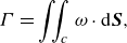 \begin{equation} \Gamma =\iint _{c}^{}\omega \cdot \mathrm{d}\boldsymbol{S}, \end{equation}
where $\omega$
is absolute vorticity, and
$\omega$
is absolute vorticity, and $c$
is the vortex-core area. Vortex-core area is defined as the region within the closed contour bounded by a vorticity magnitude of 10
$c$
is the vortex-core area. Vortex-core area is defined as the region within the closed contour bounded by a vorticity magnitude of 10 $\mathrm{s}^{-1}$
within PVCs/SVCs. Circulations were subsequently non-dimensionalised by the maximum circulation of PVCs, such that
$\mathrm{s}^{-1}$
within PVCs/SVCs. Circulations were subsequently non-dimensionalised by the maximum circulation of PVCs, such that $\Gamma ^*= \Gamma /\Gamma _{{max}}$
. Meanwhile, vortex-core centres were estimated based on the following equations:
$\Gamma ^*= \Gamma /\Gamma _{{max}}$
. Meanwhile, vortex-core centres were estimated based on the following equations:
 \begin{equation} \left . \begin{array}{ll} x_{c}=\iint _{c}^{}x\omega \cdot \mathrm{d}\boldsymbol{S}/\iint _{c}^{}\omega \cdot \mathrm{d}\boldsymbol{S},\\[8pt] y_{c}=\iint _{c}^{}y\omega \cdot \mathrm{d}\boldsymbol{S}/\iint _{c}^{}\omega \cdot \mathrm{d}\boldsymbol{S} \end{array}\right \} .\end{equation}
2.3. Key axis-switching stages of free elliptic vortex rings
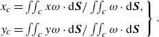
One of the most intriguing differences between CVRs and EVRs is the axis-switching behaviour of the latter. Although this phenomenon has been well documented, the key axis-switching stages and hence locations are sensitive to the EVR initial conditions, such as their aspect ratios, Reynolds numbers and how they are generated. Since the present study focuses on EVRs colliding with the wall at their key axis-switching stages, hence their locations for one complete axis-switching cycle must be ascertained first. To do that, TR-PIV experiments on freely translating EVRs were conducted first, where the vortex-core locations of both $AR=2$
and 4 EVRs were extracted along the major and minor planes from the vorticity fields and presented in figure 3. Note that lower and upper vortex-core locations for each plane were averaged to minimise experimental uncertainties.
$AR=2$
and 4 EVRs were extracted along the major and minor planes from the vorticity fields and presented in figure 3. Note that lower and upper vortex-core locations for each plane were averaged to minimise experimental uncertainties.
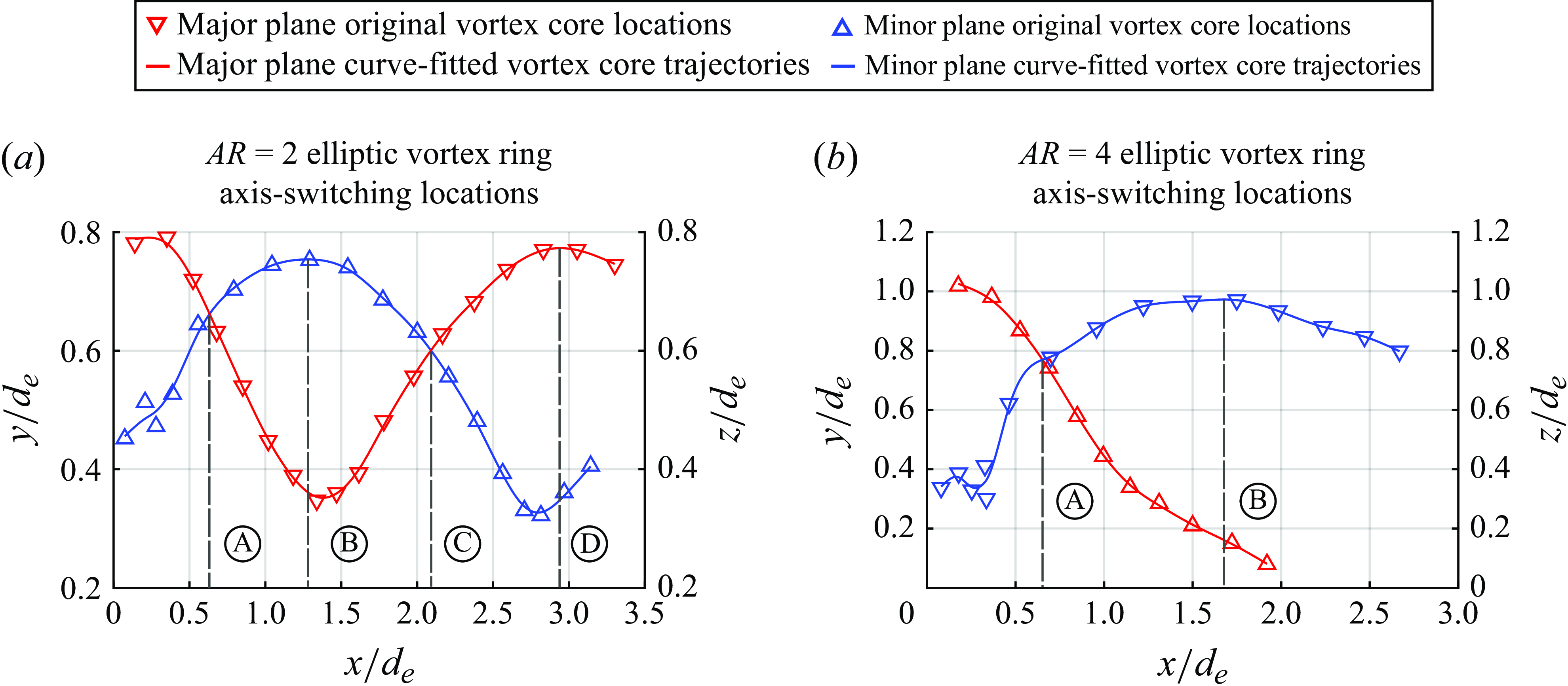
Figure 3. Averaged vortex-core trajectories extracted from TR-PIV vorticity results and key axis-switching stages identified for (a) $AR=2$
and (b)
$AR=2$
and (b) $AR=4$
free EVRs.
$AR=4$
free EVRs.
Figure 3(a) shows the key axis-switching stages and locations for $AR=2$
EVR, where the vortex-core trajectories cover slightly beyond one complete axis-switching cycle. Its major and minor diameters clearly vary as it translates downstream. Once the EVR is formed, its two segment ends along the major plane move faster downstream due to their smaller radii of curvature, where they subsequently curve inwards and towards the centreline. Incidentally, this has the effect of gradually reducing the radii of curvature for the EVR segment ends along the minor plane, which in turn leads to these segment ends behaving the same way as described above for their counterparts along the major plane. As a result, the major and minor diameters and hence axes would ‘switch’ as the EVR continues to move downstream until it loses flow coherence.
$AR=2$
EVR, where the vortex-core trajectories cover slightly beyond one complete axis-switching cycle. Its major and minor diameters clearly vary as it translates downstream. Once the EVR is formed, its two segment ends along the major plane move faster downstream due to their smaller radii of curvature, where they subsequently curve inwards and towards the centreline. Incidentally, this has the effect of gradually reducing the radii of curvature for the EVR segment ends along the minor plane, which in turn leads to these segment ends behaving the same way as described above for their counterparts along the major plane. As a result, the major and minor diameters and hence axes would ‘switch’ as the EVR continues to move downstream until it loses flow coherence.
Four key axis-switching stages can be identified as points A, B, C and D as indicated in the figure. Points A and C are when the major and minor diameters are similar, while points B and D are when the EVR incurs the first and second axis-switching instances. Point D is also the point when the EVR almost reverts back to its original state. While the maximum and minimum diameters associated with points B and D do not exactly align with the same dimensionless streamwise distance, a decision was made to use streamwise distances associated with the maximum diameter. While this approach introduces some discrepancies in the streamwise distances, they are sufficiently small to reflect the drastic differences in the major and minor diameters at points B and D. Lastly, as these four key axis-switching stages are relatively evenly distributed, they will be known as the quarter-, half-, three-quarter and fullcycle to ease better appreciation of their relative stages and locations.
The corresponding vortex-core trajectories for the $AR=4$
EVR are shown in figure 3(b) and their axis-switching behaviour differs from that of the
$AR=4$
EVR are shown in figure 3(b) and their axis-switching behaviour differs from that of the $AR=2$
EVR. Rather than an oscillatory interchanging of the major and minor axes, there is only one cross-over point in the trajectories. However, this can be understood if one appreciates that an
$AR=2$
EVR. Rather than an oscillatory interchanging of the major and minor axes, there is only one cross-over point in the trajectories. However, this can be understood if one appreciates that an $AR=4$
EVR will undergo bifurcation behaviour, as reported by Oshima et al. (Reference Oshima, Izutsu, Oshima and Hussain1988), Hussain & Husain (Reference Hussain and Husain1989) and Cheng et al. (Reference Cheng, Lou and Lim2016) earlier. Bifurcation is essentially a vortex disconnection and reconnection process, whereby the two vortex-ring segments along the major plane come into contact with each other after they move inwards and towards the centreline, thereby producing two sub-vortexrings and disrupting the axis-switching behaviour. As this study focuses on EVR collisions before bifurcations happen, effects of bifurcations on their collisions will not be discussed in detail here. In turn, the key axis-switching locations identified for the
$AR=4$
EVR will undergo bifurcation behaviour, as reported by Oshima et al. (Reference Oshima, Izutsu, Oshima and Hussain1988), Hussain & Husain (Reference Hussain and Husain1989) and Cheng et al. (Reference Cheng, Lou and Lim2016) earlier. Bifurcation is essentially a vortex disconnection and reconnection process, whereby the two vortex-ring segments along the major plane come into contact with each other after they move inwards and towards the centreline, thereby producing two sub-vortexrings and disrupting the axis-switching behaviour. As this study focuses on EVR collisions before bifurcations happen, effects of bifurcations on their collisions will not be discussed in detail here. In turn, the key axis-switching locations identified for the $AR=4$
EVR will be points A and B, where they are associated with the first instance when the major and minor axes are similar and when the minor diameter increases to a maximum and becomes the major diameter (i.e. quarter- and half-cycles). Table 1 summarises all the non-dimensional streamwise distances (i.e.
$AR=4$
EVR will be points A and B, where they are associated with the first instance when the major and minor axes are similar and when the minor diameter increases to a maximum and becomes the major diameter (i.e. quarter- and half-cycles). Table 1 summarises all the non-dimensional streamwise distances (i.e. $s/d_e$
) for all key axis-switching stages for both EVRs, which would be used to set the separation distances between the orifice and flat wall.
$s/d_e$
) for all key axis-switching stages for both EVRs, which would be used to set the separation distances between the orifice and flat wall.
Table 1. Dimensionless locations, $s/d_e$
, associated with the quarter-, half-, three-quarter and fullcycles of the axis-switching behaviour for
$s/d_e$
, associated with the quarter-, half-, three-quarter and fullcycles of the axis-switching behaviour for $AR=2$
and 4 free EVRs.
$AR=2$
and 4 free EVRs.
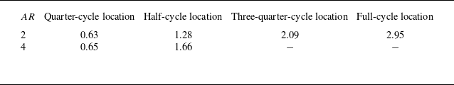
Figure 4(a) shows the $AR=2$
and 4 EVR states and their distortionary motions at each key axis-switching location. This was done by reconstructing the instantaneous 3-D vortex filaments for both EVRs, based on previous experimental results and observations. The EVRs undergo different motions along different vortex filament segments due to axisswitching, where the arrows indicate the more dominant directions. To enable more intuitive understanding of the flow mechanisms leading to the experimental results, figures 4(a)–4(b) further show how these two EVRs and distortionary motions look like along the major and minor planes when they are at the key axis-switching locations.
$AR=2$
and 4 EVR states and their distortionary motions at each key axis-switching location. This was done by reconstructing the instantaneous 3-D vortex filaments for both EVRs, based on previous experimental results and observations. The EVRs undergo different motions along different vortex filament segments due to axisswitching, where the arrows indicate the more dominant directions. To enable more intuitive understanding of the flow mechanisms leading to the experimental results, figures 4(a)–4(b) further show how these two EVRs and distortionary motions look like along the major and minor planes when they are at the key axis-switching locations.
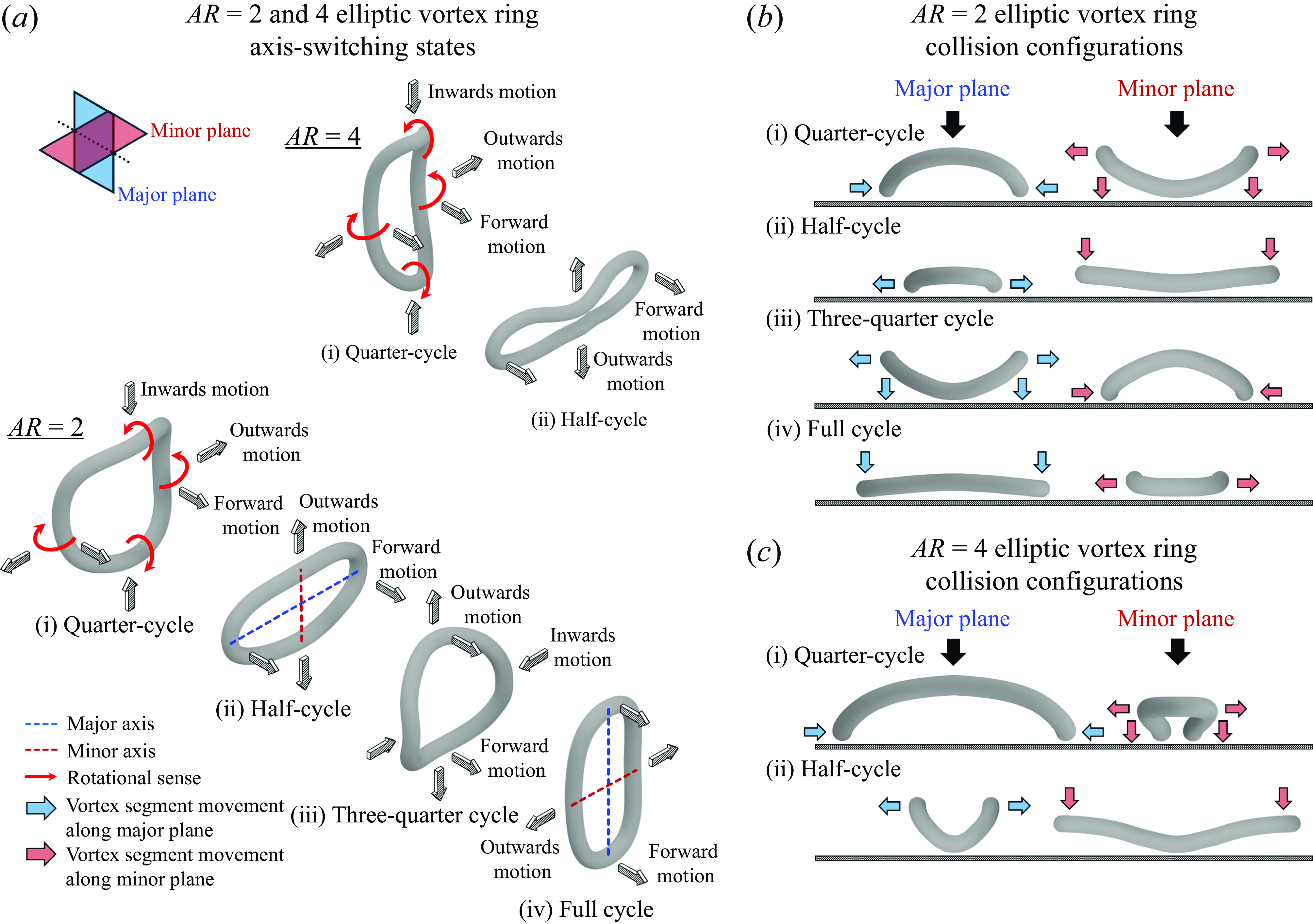
Figure 4. Sketch showing the 3-D structures of (a) $AR=2$
and 4 freely translating EVRs at each key axis-switching location and collision configurations for (b)
$AR=2$
and 4 freely translating EVRs at each key axis-switching location and collision configurations for (b) $AR=2$
and (c)
$AR=2$
and (c) $AR=4$
EVRs.
$AR=4$
EVRs.
2.4. Validation of PLIF visualisation technique
To establish a baseline for comparisons later as well as validating that the PLIF technique can capture consistent collision dynamics like TR-PIV measurements, the flow developments associated with CVR colliding with the flat wall at the full-cycle location of $AR=2$
EVR were studied using both these techniques.
$AR=2$
EVR were studied using both these techniques.
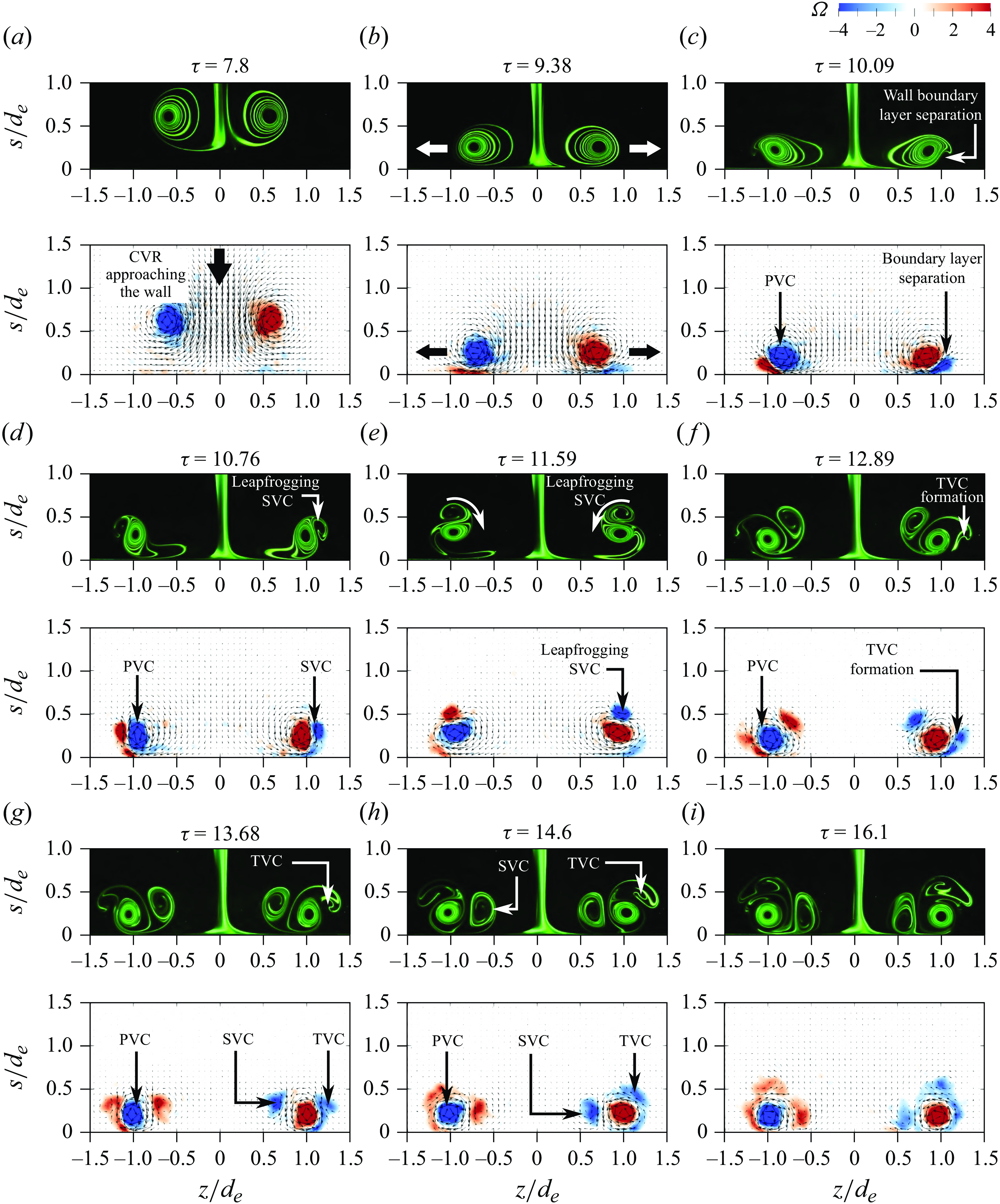
Figure 5. Comparisons between PLIF visualisations and vorticity fields measured by TR-PIV of the CVR colliding with the flat wall at the $AR=2$
EVR full-cycle location along the minor plane.
$AR=2$
EVR full-cycle location along the minor plane.
Figure 5 compares PLIF visualisation and vorticity results captured for CVR collision, where the non-dimensional time, $\tau$
, is defined as
$\tau$
, is defined as $\tau =tU/d_e$
, and
$\tau =tU/d_e$
, and $t$
is the absolute time. Due to good axisymmetry of the CVRs observed during the study, flow developments along major and minor planes are highly similar. Thus, the comparison was only conducted along the minor plane. Note that
$t$
is the absolute time. Due to good axisymmetry of the CVRs observed during the study, flow developments along major and minor planes are highly similar. Thus, the comparison was only conducted along the minor plane. Note that $\tau =0$
is set to the instance when the piston started to move. Non-dimensional vorticity is calculated using the equation
$\tau =0$
is set to the instance when the piston started to move. Non-dimensional vorticity is calculated using the equation $\Omega =\omega d_{e}/U$
, where
$\Omega =\omega d_{e}/U$
, where $\omega$
is the absolute vorticity. Similar to the vortical developments observed by earlier studies, the early stages of collision witness the flattening of PVCs and radial expansion of primary vortex-ring diameter, as can be observed in figures 5(a)–5(b). Subsequently, figures 5(d)–5(e) show the SVCs form from wall boundary layer separation before they leapfrog over the PVCs. Thereafter, the formation of TVCs and its entrainment by the PVCs in the same manner as the SVCs before can be seen in figures 5(f)–5(i). Note that the entrained SVCs remain relatively coherent within the confines of the PVCs in figure 5(i), and that vorticity results are able to confirm that the dyestreak produced by the CVR as it translates towards the flat wall is due to excess dye rather than the presence of any trailingjet. Thus, there are good agreements between both techniques and PLIF visualisations will primarily be used to describe the collision vortex dynamics, unless TR-PIV results are able provide additional flow details.
$\omega$
is the absolute vorticity. Similar to the vortical developments observed by earlier studies, the early stages of collision witness the flattening of PVCs and radial expansion of primary vortex-ring diameter, as can be observed in figures 5(a)–5(b). Subsequently, figures 5(d)–5(e) show the SVCs form from wall boundary layer separation before they leapfrog over the PVCs. Thereafter, the formation of TVCs and its entrainment by the PVCs in the same manner as the SVCs before can be seen in figures 5(f)–5(i). Note that the entrained SVCs remain relatively coherent within the confines of the PVCs in figure 5(i), and that vorticity results are able to confirm that the dyestreak produced by the CVR as it translates towards the flat wall is due to excess dye rather than the presence of any trailingjet. Thus, there are good agreements between both techniques and PLIF visualisations will primarily be used to describe the collision vortex dynamics, unless TR-PIV results are able provide additional flow details.
Lastly, the PLIF visualisation technique is further validated by comparing the PVC and SVC trajectories extracted from both PLIF visualisation images and TR-PIV results associated with $AR=2$
EVR collisions at full-cycle location along major and minor planes. Similar to the study of New & Zang (Reference New and Zang2017), the trajectories of PVCs extracted from both methods align with each other well. While the discrepancies between SVCs extracted from both methods become larger at the later stages of collisions, this can be attributed to the fact that the fluorescent dye in this study was released inside the tube where the vortex rings were generated. Consequently, the SVCs cannot entrain as much dye as the PVCs, thus increasing the uncertainty of tracking the SVCs. The TR-PIV-based vortex-core trajectories would be more reliable and hence preferred over PLIF visualisation-based vortex-core trajectories. With this in mind, the vortex-core trajectories presented later will be based on TR-PIV results.
$AR=2$
EVR collisions at full-cycle location along major and minor planes. Similar to the study of New & Zang (Reference New and Zang2017), the trajectories of PVCs extracted from both methods align with each other well. While the discrepancies between SVCs extracted from both methods become larger at the later stages of collisions, this can be attributed to the fact that the fluorescent dye in this study was released inside the tube where the vortex rings were generated. Consequently, the SVCs cannot entrain as much dye as the PVCs, thus increasing the uncertainty of tracking the SVCs. The TR-PIV-based vortex-core trajectories would be more reliable and hence preferred over PLIF visualisation-based vortex-core trajectories. With this in mind, the vortex-core trajectories presented later will be based on TR-PIV results.
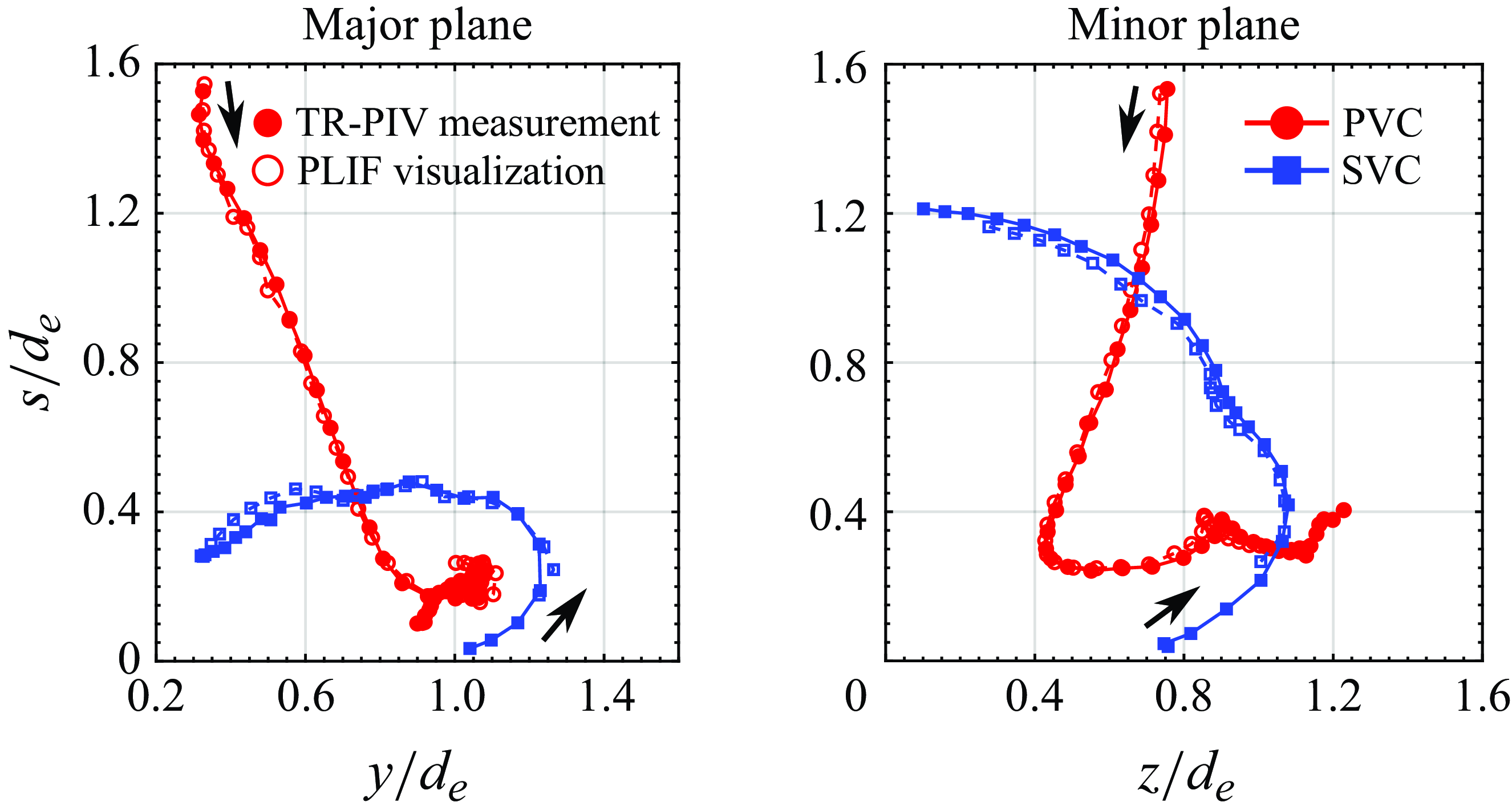
Figure 6. Comparisons of PVC and SVC trajectories extracted from PLIF visualisation images and TR-PIV results associated with $AR=2$
EVR collisions at full-cycle location along both the major plane and minor plane.
$AR=2$
EVR collisions at full-cycle location along both the major plane and minor plane.
3. Results and discussions
3.1. The case of AR = 2 elliptic vortex-ring collisions
The PLIF visualisations for $AR=2$
EVR collisions at key axis-switching stages will now be presented and discussed. Results will be presented from the largest to the smallest separation distance (i.e from full-, three-quarter, half- to quarter-cycles). Note that the PLIF images across different figures are not of the same scale, due to different physical radial extents of the vortex dynamics.
$AR=2$
EVR collisions at key axis-switching stages will now be presented and discussed. Results will be presented from the largest to the smallest separation distance (i.e from full-, three-quarter, half- to quarter-cycles). Note that the PLIF images across different figures are not of the same scale, due to different physical radial extents of the vortex dynamics.
3.1.1. Full-cycle collision behaviour
Figures 7 and 8 (see supplementary movies 1 and 2) present PLIF visualisations taken for the $AR=2$
EVR collision at the full-cycle location along the major and minor planes, respectively. Along the major plane, the early stages as shown by figures 7(a)–7(c) are quite similar to the CVR collision. Not only do the PVCs flatten, but SVCs are formed due to wall boundary layer separations before they begin to leapfrog over the PVCs, as can be observed in figures 7(d)–7(e). Subsequently, however, figures 7(f)–7(i) reveal that the SVCs move towards the collision axis almost horizontally instead of getting entrained into the PVC confines. At the same time, TVCs are produced by a second wall boundary layer separation, as shown in figure 7(g), and are entrained by the increasingly smaller PVCs at a much quicker pace. Shortly after that, as shown in figure 7(j), the PVCs have transitioned into incoherence while the SVCs have finally moved into their confines. Intriguingly, figure 7(k) shows a vortex structure along the collision axis crossing the laser sheet. As it descends towards the flat wall shown in figure 7(l), a pair of vortex structures pair up with the SVCs to form two vortexdipoles that move away from the collision axis. This will be discussed in a later section.
$AR=2$
EVR collision at the full-cycle location along the major and minor planes, respectively. Along the major plane, the early stages as shown by figures 7(a)–7(c) are quite similar to the CVR collision. Not only do the PVCs flatten, but SVCs are formed due to wall boundary layer separations before they begin to leapfrog over the PVCs, as can be observed in figures 7(d)–7(e). Subsequently, however, figures 7(f)–7(i) reveal that the SVCs move towards the collision axis almost horizontally instead of getting entrained into the PVC confines. At the same time, TVCs are produced by a second wall boundary layer separation, as shown in figure 7(g), and are entrained by the increasingly smaller PVCs at a much quicker pace. Shortly after that, as shown in figure 7(j), the PVCs have transitioned into incoherence while the SVCs have finally moved into their confines. Intriguingly, figure 7(k) shows a vortex structure along the collision axis crossing the laser sheet. As it descends towards the flat wall shown in figure 7(l), a pair of vortex structures pair up with the SVCs to form two vortexdipoles that move away from the collision axis. This will be discussed in a later section.
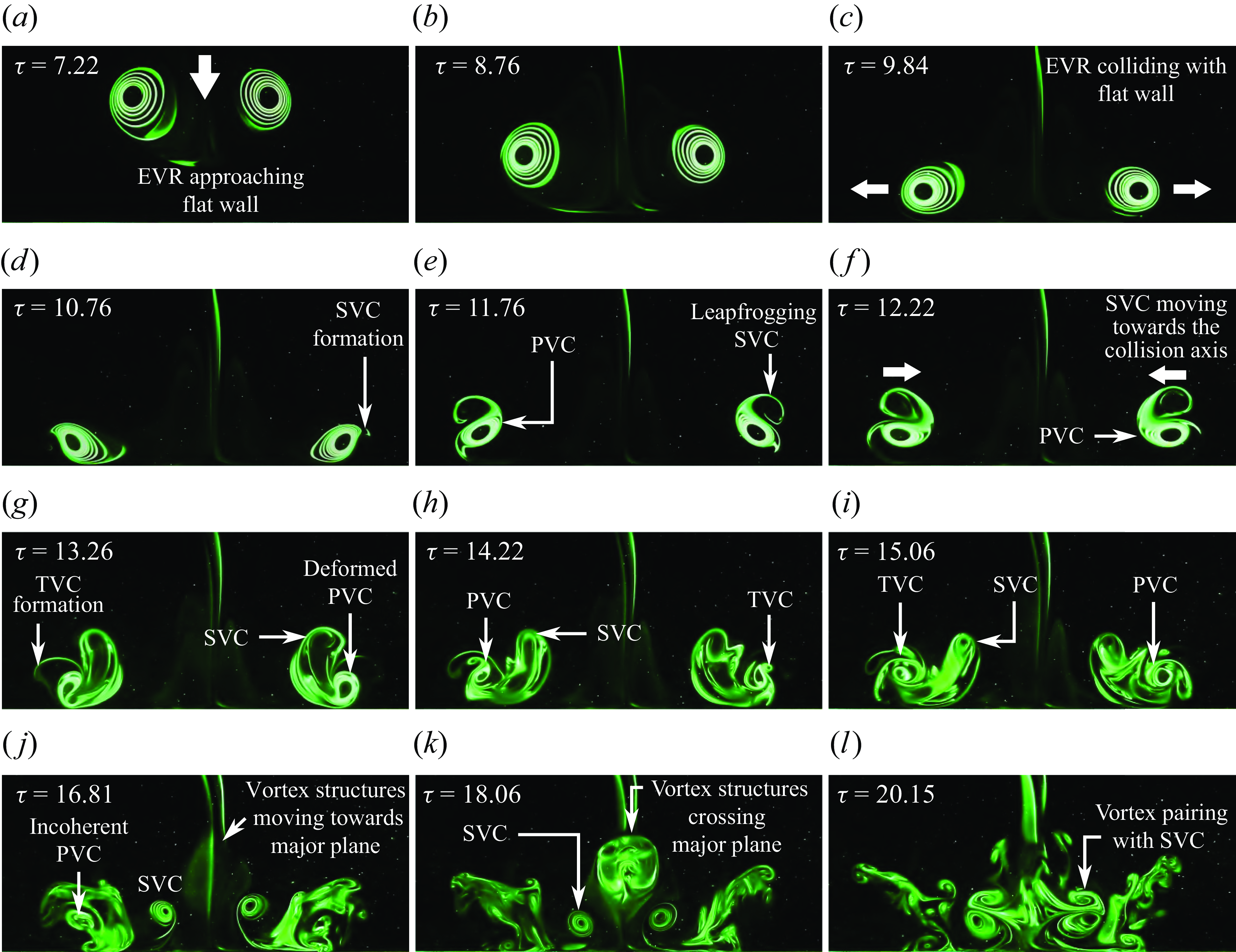
Figure 7. Instantaneous PLIF visualisations along the major plane of the $AR=2$
EVR colliding with the wall at the full-cycle location.
$AR=2$
EVR colliding with the wall at the full-cycle location.
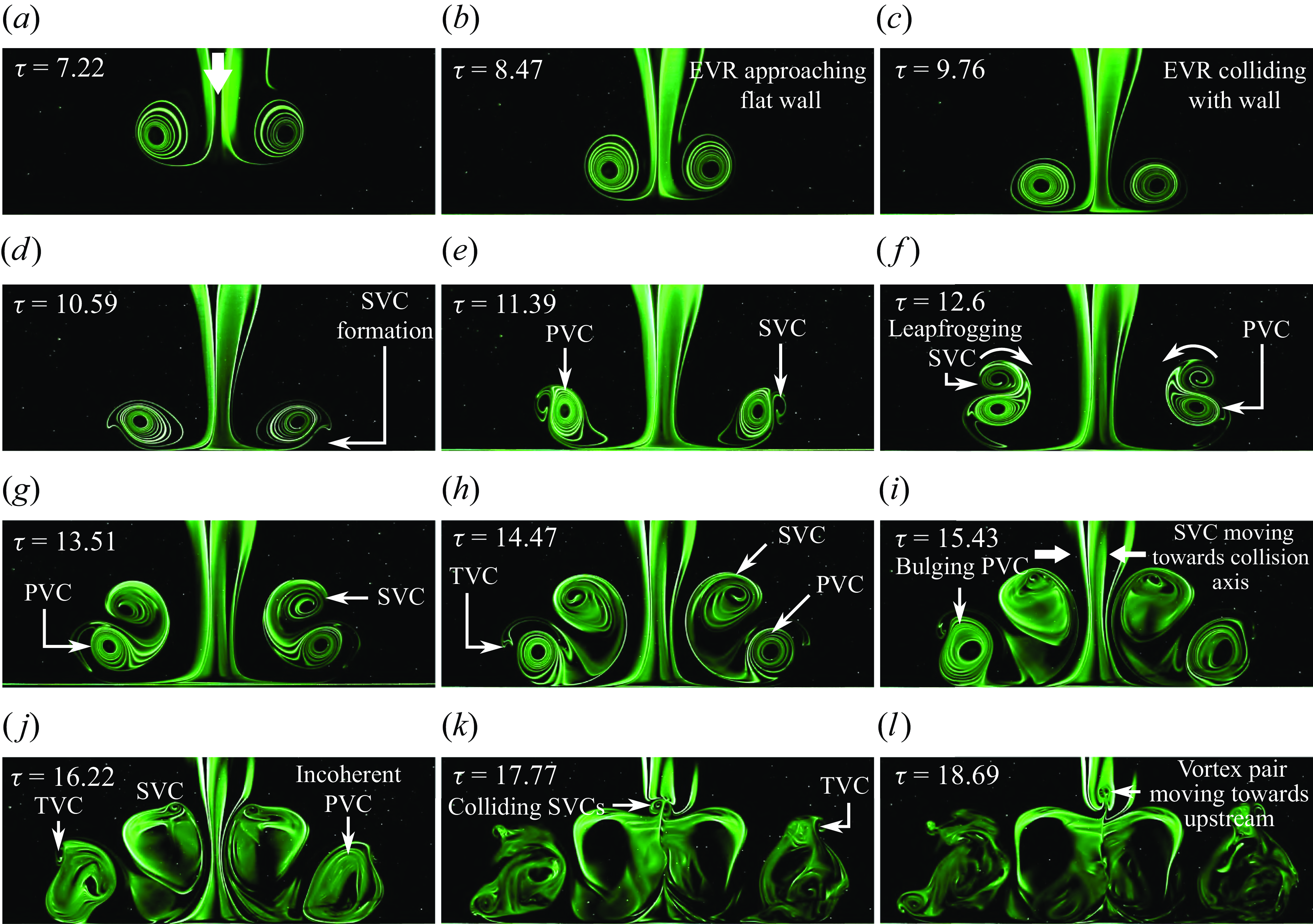
Figure 8. Instantaneous PLIF visualisations along the minor plane of the $AR=2$
EVR colliding with the wall at the full-cycle location.
$AR=2$
EVR colliding with the wall at the full-cycle location.
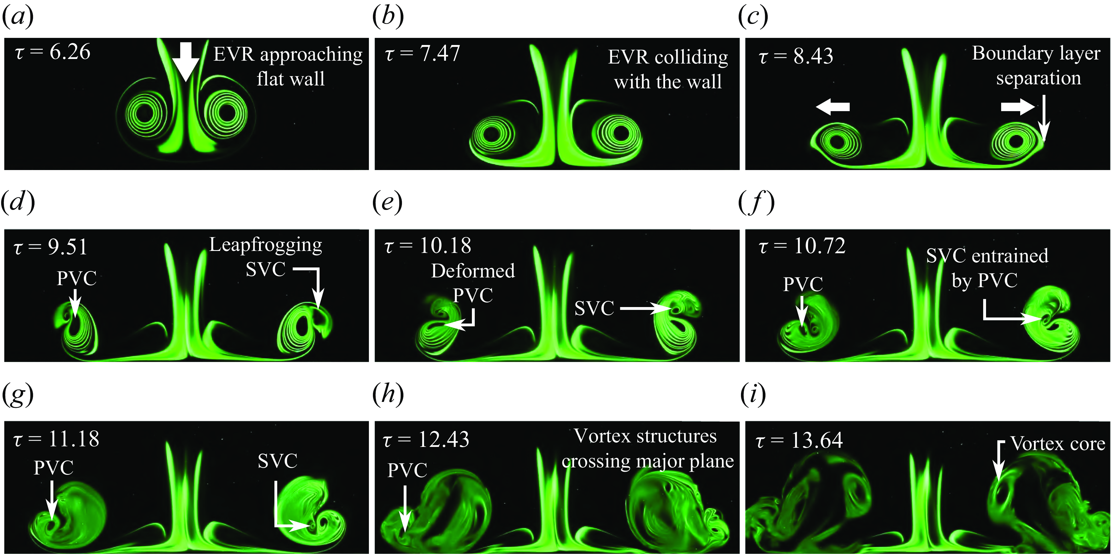
Figure 9. Instantaneous PLIF visualisations along the major plane of the $AR=2$
EVR colliding with the wall at the three-quarter-cycle location.
$AR=2$
EVR colliding with the wall at the three-quarter-cycle location.
Moving to the minor plane, the gradual EVR diameter reduction as part of the axis-switching behaviour while it approaches the wall can be observed in figures 8(a)–8(b). Similar to that along the major plane, formations of SVCs and their subsequent leapfrogging over the PVCs can also be seen in figures 8(d)–8(f). Curiously, figures 8(g)–8(j) reveal that the leapfrogging process does not involve the SVCs moving into the PVC confines, but rather they move upstream and towards the collision axis, as well as becoming more bulbous.
Concurrently, TVCs form and engage in a similar leapfrogging process, with the PVCs transitioning to a more bulbous and incoherent state as well. The latter could explain why the TVCs are not fully entrained by the PVCs but become incoherent half-way through, as seen in figures 8(k)–8(l). On the other hand, the now physically small SVCs eventually meet along the collision axis to produce a small vortexdipole. Note that this behaviour would explain the vortex structures crossing the lasersheet observed in figure 7(k). Furthermore, vortex cores that become increasingly smaller or bulbous during wall-based collisions are indications of vortexstretching or compression due to non-zero circumferential flows along the vortex-ring filament, as demonstrated earlier by Lim (Reference Lim1989) and New et al. (Reference New, Long, Zang and Shi2020). Thus, vortexstretching and compression dominate along the major plane and minor plane, respectively. Specifically, circumferential flows along the various primary and SVR filaments are directed from the major plane towards the minor plane for collision at this location.
3.1.2. Three-quarter-cycle collision behaviour
This section will discuss the collision behaviour at the three-quarter-cycle location. Figures 9(a)–9(f) show that the collision behaviour is quite similar to that along the major plane at the full-cycle location, at least in how the SVCs form and leapfrog over the PVCs (see supplementary movie 3). As the SVCs leapfrog over the PVCs, as shown in figure 9(f), both of them decrease in physical size. It can be assumed that vortexstretching due to circumferential flows underpins these observations and flows are directed away from the major plane. At the same time, new vortex structures adjacent to the SVCs cross the lasersheet in the same figure as well. These vortex structures become bulbous and grow incoherent, as shown in figures 9(g)–9(h), until eventually a pair of vortex cores shows up very clearly in figure 9(i). Interestingly, no TVCs can be discerned to form for this collision, presumably due to the weaker PVCs at the later flow stages.
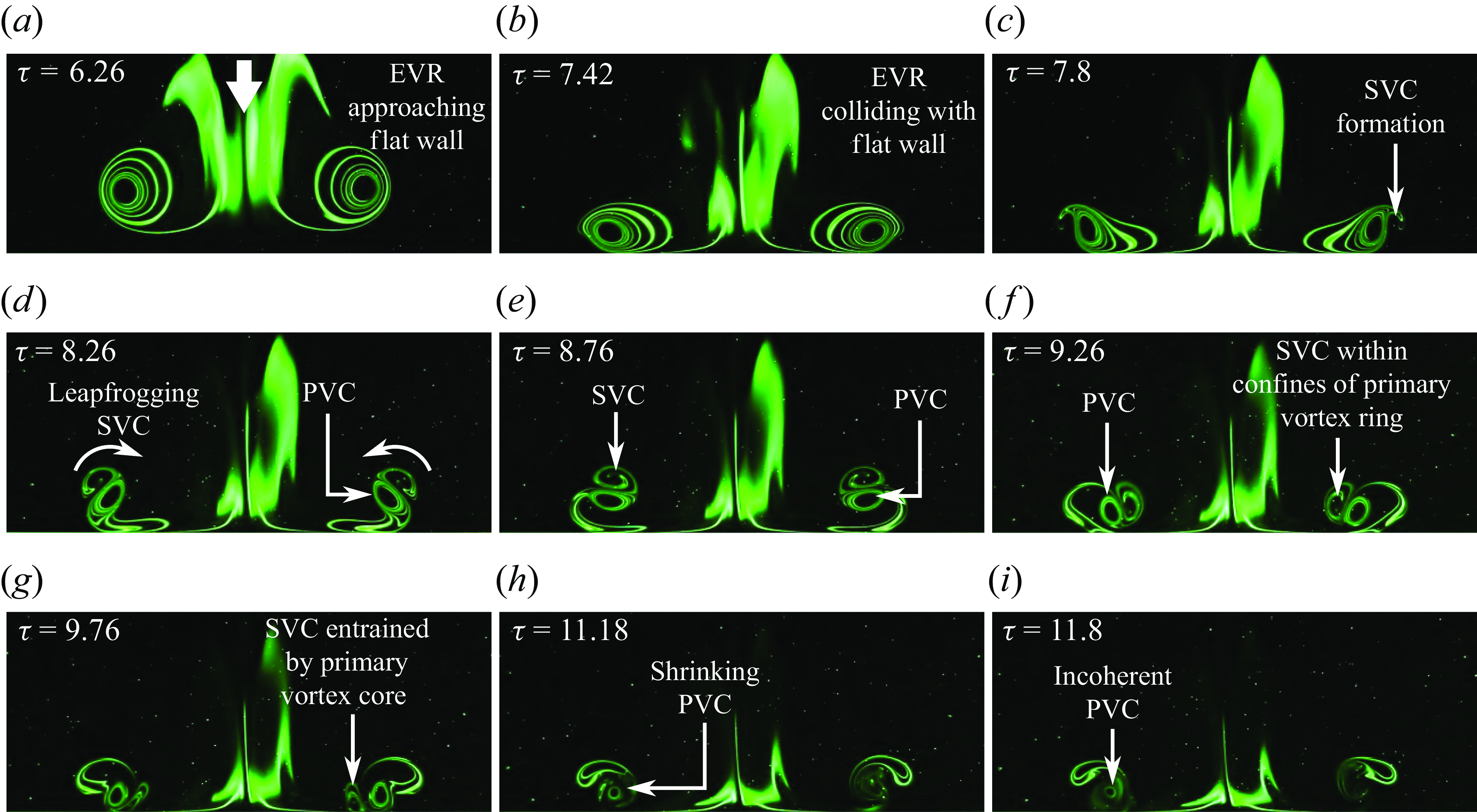
Figure 10. Instantaneous PLIF visualisations along the minor plane of the $AR=2$
EVR colliding with the wall at the three-quarter-cycle location.
$AR=2$
EVR colliding with the wall at the three-quarter-cycle location.
PLIF visualisations along the minor plane are presented in figure 10 (see supplementary movie 4) and the collision behaviour is surprisingly similar to CVR collision. Hence, these similar flow details will not be elaborated here but, instead, emphasis will be placed upon the differences. Firstly, PVC, SVC and TVC sizes decrease much more rapidly than those observed in CVR collision, thus indicating higher vortex-stretching levels along both major and minor planes. Secondly, there exists a lag between the formation and entrainment of SVCs by the PVCs along both planes. Take, for instance, figures 9(c) and 10(d), which are very close in timingsand which show that the vortical processes are more rapid along the minor plane than the major plane. This reveals that both the formation and entrainment of SVCs initiate from the minor plane before propagating towards major plane, which provides important clues on the flow mechanisms. In contrast, there is practically no such lag for the collision at full-cycle location. Lastly, while it may seem like TVCs do not form along the minor plane, TR-PIV results show otherwise. As can be discerned in the vorticity results along the same plane shown in figure 11(d), very small-scale TVCs form after the SVCs are completely entrained by the PVCs. However, these TVCs become incoherent very rapidly and would explain why they are difficult to capture via PLIF visualisations.
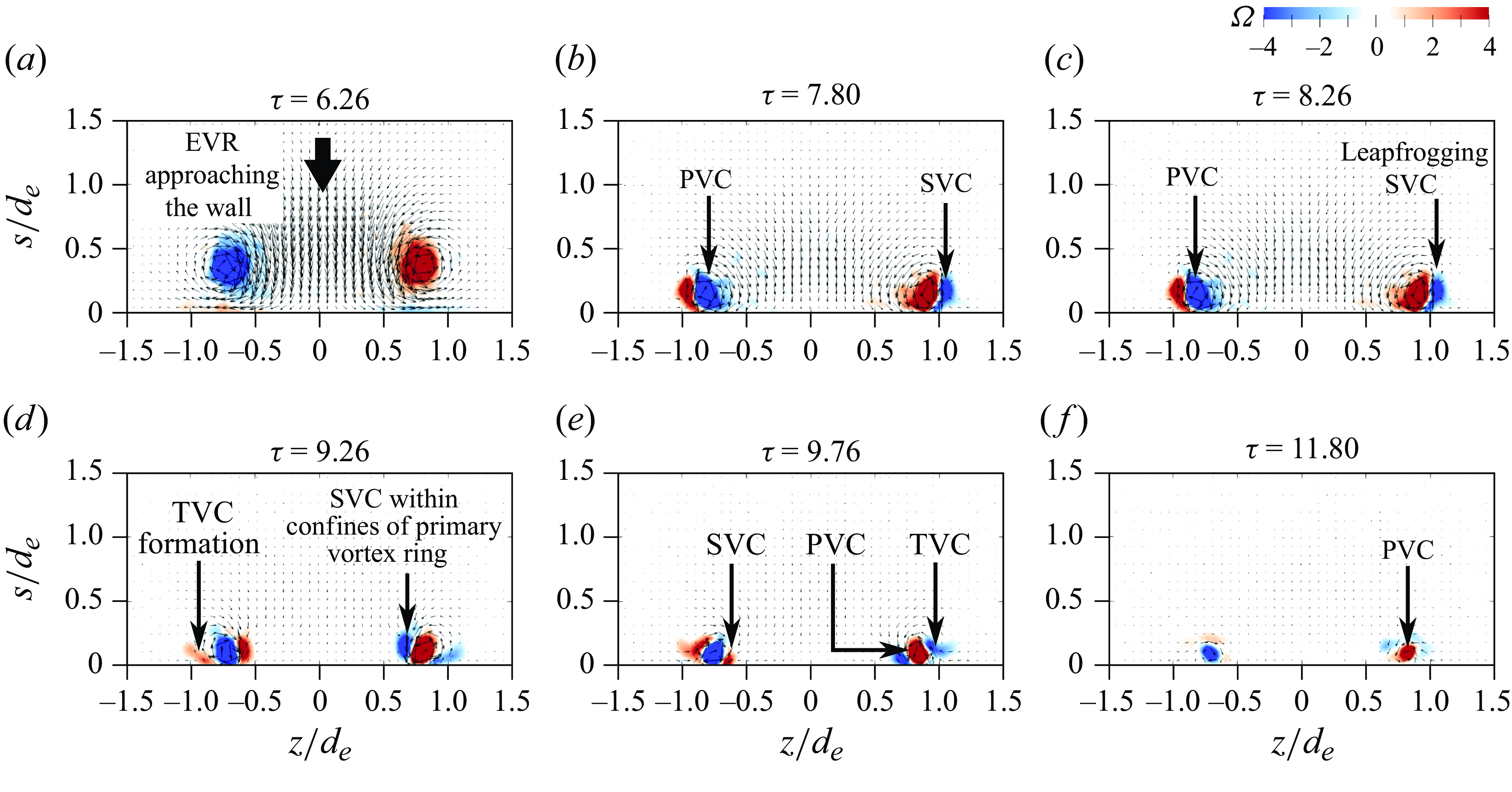
Figure 11. Instantaneous vorticity distributions along the minor plane of the $AR=2$
EVR colliding with the wall at the three-quarter-cycle location.
$AR=2$
EVR colliding with the wall at the three-quarter-cycle location.
3.1.3. Half-cycle collision behaviour
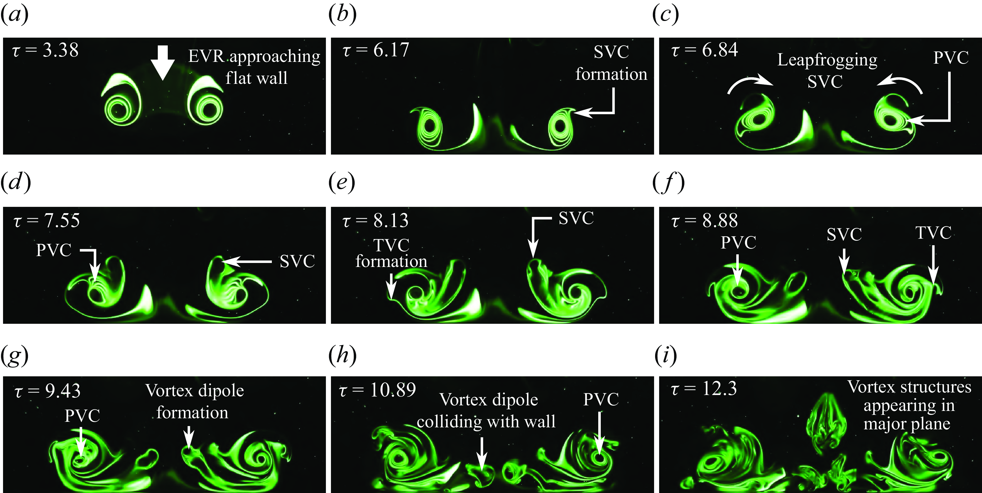
Figure 12. Instantaneous PLIF visualisations along the major plane of the $AR=2$
EVR colliding with the wall at the half-cycle location.
$AR=2$
EVR colliding with the wall at the half-cycle location.
Starting with the PLIF visualisations taken along the major plane (see supplementary movie 5), a moderate increase in the EVR diameter shown in figures 12(a)–12(b) during the early stages of the collision is more similar to the scenario observed earlier along the minor plane at full-cycle location in figures 8(a)–8(c). This is due to the fact that the EVR would have its major and minor axes rotated by 90 $^{\circ }$
at this point (see figure 4
b(ii)) as compared with the full-cycle location (see figure 4
b(iv)). Subsequently, the SVCs are entrained by the PVCs while taking on increasingly loop-like outlines, as shown in figures 12(c)–12(f). Around the same time, TVCs are produced as seen in figure 12(e) and get entrained by the PVCs as well.
$^{\circ }$
at this point (see figure 4
b(ii)) as compared with the full-cycle location (see figure 4
b(iv)). Subsequently, the SVCs are entrained by the PVCs while taking on increasingly loop-like outlines, as shown in figures 12(c)–12(f). Around the same time, TVCs are produced as seen in figure 12(e) and get entrained by the PVCs as well.
Returning to the entrained SVCs, they translate towards the collision axis and appear to evolve into two vortexdipoles, before they collide with the wall while within the confines of the PVCs, shown in figures 12(g)–12(h). Shortly after, additional coherent vortex structures begin to appear along the collision axis in figure 12(i) in the same manner seen in figure 7(k) earlier. To better understand the behaviour of SVCs, vorticity results along the major plane are presented in figure 13 (see supplementary movie 6). Figure 13(f) confirms the manifestation of the vortexdipoles from the SVCs. In particular, the counter-rotating nature of each vortexdipole is now more apparent, even as both of them move towards the collision axis and subsequently the wall, as shown in figures 13(g)–13(h). It should be highlighted that similar manifestations of vortexdipoles were observed earlier by New & Zang (Reference New and Zang2017) and New et al. (Reference New, Gotama and Vevek2021), where they were brought on by vortex disconnection and reconnection processes encountered during round cylinder-based vortex-ring collisions. Hence, it is very likely similar flow processes underpin the present vortex-dipole formations as well.

Figure 13. Instantaneous vorticity fields along the major plane of the $AR=2$
EVR colliding with the wall at the half-cycle location.
$AR=2$
EVR colliding with the wall at the half-cycle location.
The PLIF visualisations along the minor plane in figure 14 (see supplementary movie 7) show that SVC/TVC formations and their subsequent entrainment resemble those observed for CVR collision. Nevertheless, the relatively faster shrinking of their physical sizes in figure 14 is reflective of higher vortex-stretching levels along this plane. Meanwhile, due to the proximity of this collision point to the orifice, a stopping vortex is produced when the piston stops abruptly after completing the impulse stage, as shown in figure14(b). Figures 14(c)–14(g) prove that it does not engage in the collision and remains at almost the same location just aft of the orifice until it gradually dissipates. Figures 14(g)–14(h) show that the entrained SVCs actually move between the wall and PVCs, suggesting significant vortex entangling behaviour during the collision. Furthermore, additional vortex structures begin to appear above the PVCs, SVCs and TVCs in figures 14(h)–14(i), which are the minor-plane manifestations of the same vortex structures seen along the major plane in figure 12(i) previously. At this point, it appears that they are associated with vortex loops colliding with each other. To paint a clearer picture on the vortex entangling behaviour as well as the colliding vortex loops, vorticity results along the minor plane are presented in figure 15 (see supplementary movie 8). In particular, velocity vectors surrounding the vortex structures appearing in the minor plane in figure 15(f) further support the existence of colliding vortex loops.
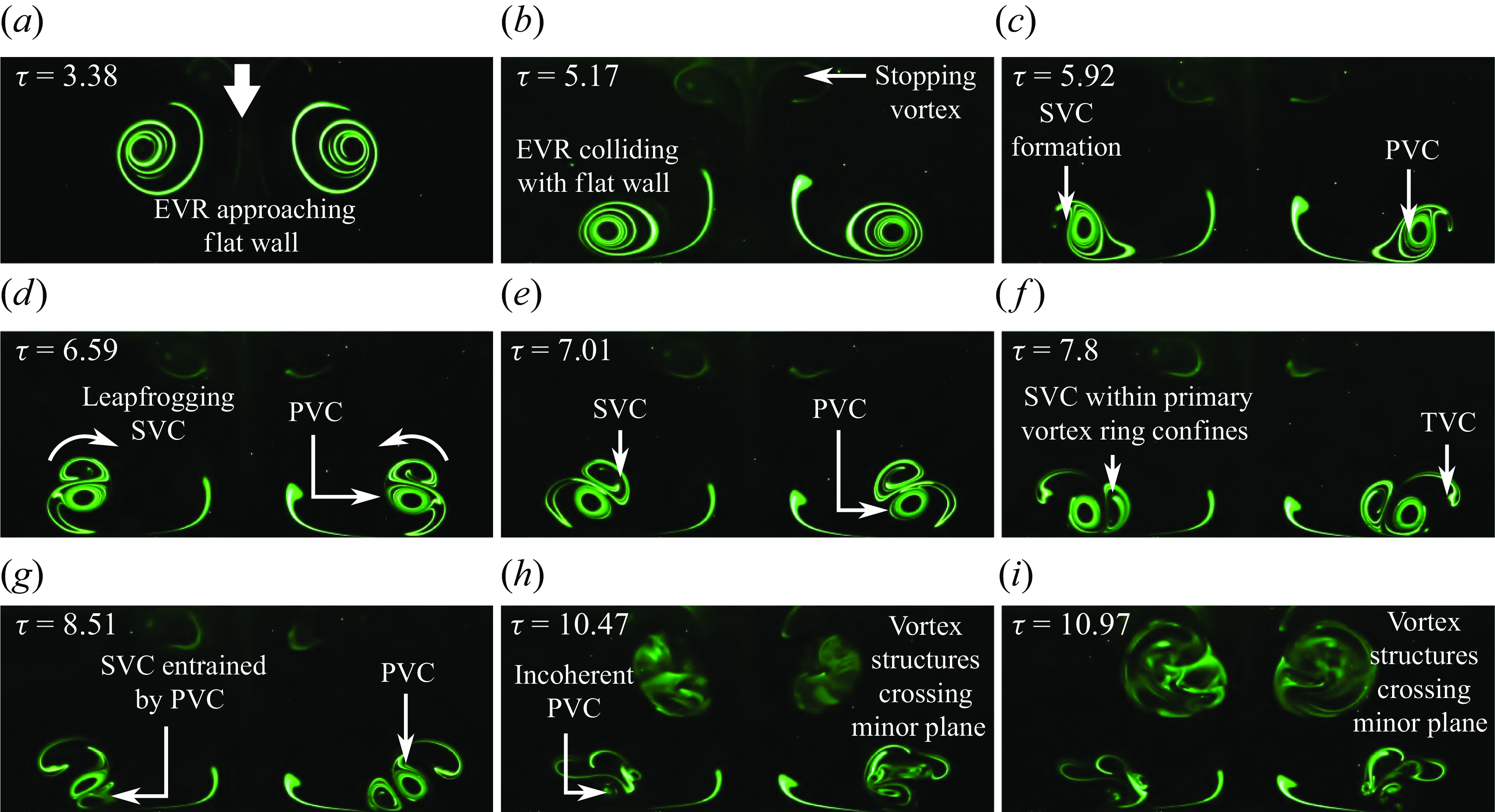
Figure 14. Instantaneous PLIF visualisations along the minor plane of the $AR=2$
EVR colliding with the wall at the half-cycle location.
$AR=2$
EVR colliding with the wall at the half-cycle location.
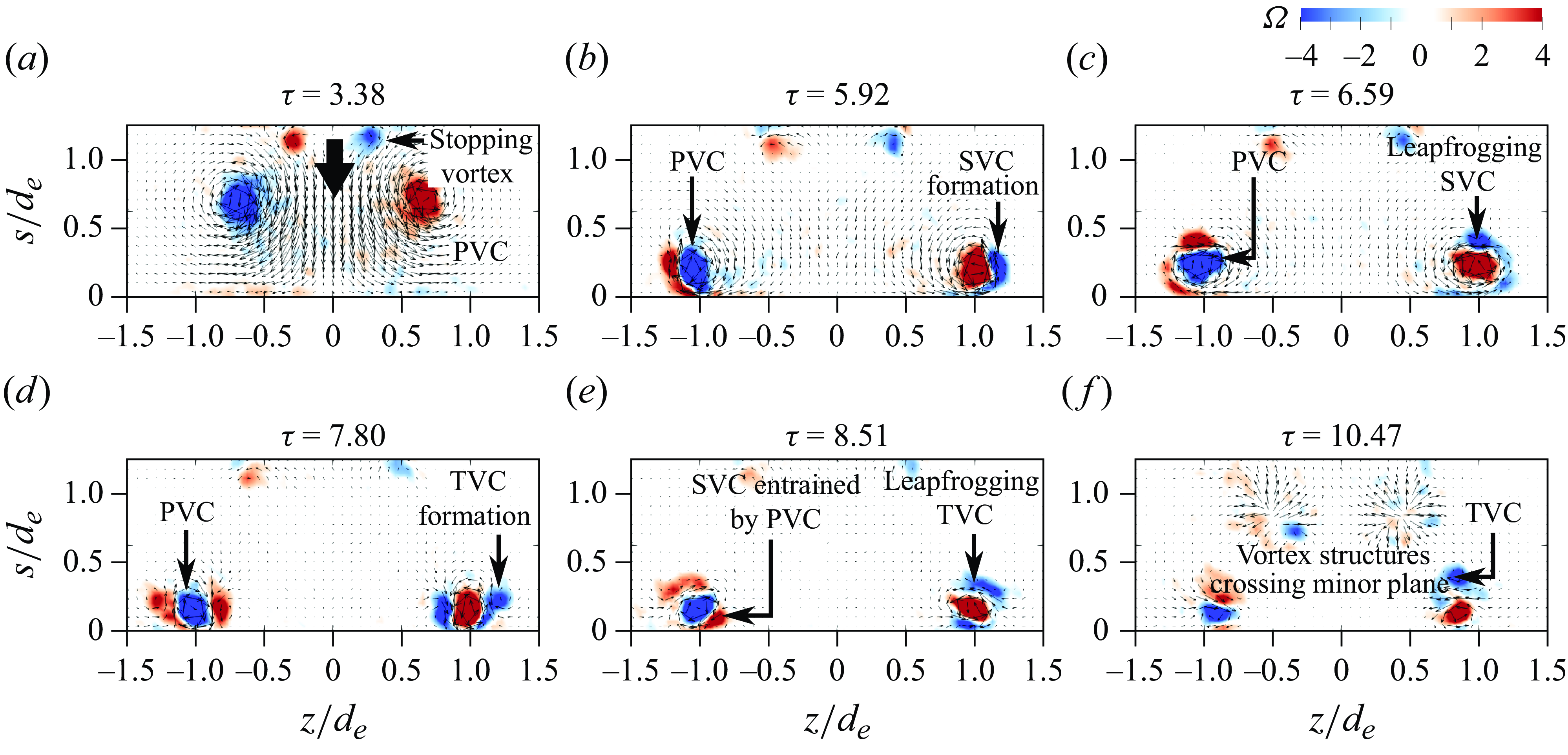
Figure 15. Instantaneous vorticity fields along the minor plane of the $AR=2$
EVR colliding with the wall at the half-cycle location.
$AR=2$
EVR colliding with the wall at the half-cycle location.
3.1.4. Quarter-cycle collision behaviour
The collision behaviour at the closest location to the orifice is not only dependent on the exact EVR axis-switching stage (see figure 4
b(i)) but also subjected to confinement effects imposed by the wall and orificewall. Figure 16 presents PLIF visualisations taken along the major plane and to emphasise how close the flat wall is to the orifice, both the orifice and orificewall are highlighted in the figure. The piston has already stopped at around $\tau =1.38$
, just before the EVR is in the state seen in figure 16(a). Despite confinement effects, however, the collision behaviour revealed along this plane does not deviate much from the typical SVC/TVC formations and entrainment as shown in figures 16(b)–16(d). In figures 16(e)–16(g), the entrained SVCs move to between the PVCs and the wall, before they emerge beyond the PVCs again. This is indicative of the SVR filament entangling around the primary vortex-ring filament, similar to what has been seen along the minor plane at three-quarter and half-cycle collision locations earlier on. While not obvious in the PLIF visualisations, the TVCs likely partake in similar behaviour. All the vortex-core physical sizes can also be seen to reduce gradually as the collision unfolds up to figure 16(h), revealing significant vortex-stretching levels similar to those observed along the minor plane at three-quarter and half-cycle collision locations previously.
$\tau =1.38$
, just before the EVR is in the state seen in figure 16(a). Despite confinement effects, however, the collision behaviour revealed along this plane does not deviate much from the typical SVC/TVC formations and entrainment as shown in figures 16(b)–16(d). In figures 16(e)–16(g), the entrained SVCs move to between the PVCs and the wall, before they emerge beyond the PVCs again. This is indicative of the SVR filament entangling around the primary vortex-ring filament, similar to what has been seen along the minor plane at three-quarter and half-cycle collision locations earlier on. While not obvious in the PLIF visualisations, the TVCs likely partake in similar behaviour. All the vortex-core physical sizes can also be seen to reduce gradually as the collision unfolds up to figure 16(h), revealing significant vortex-stretching levels similar to those observed along the minor plane at three-quarter and half-cycle collision locations previously.
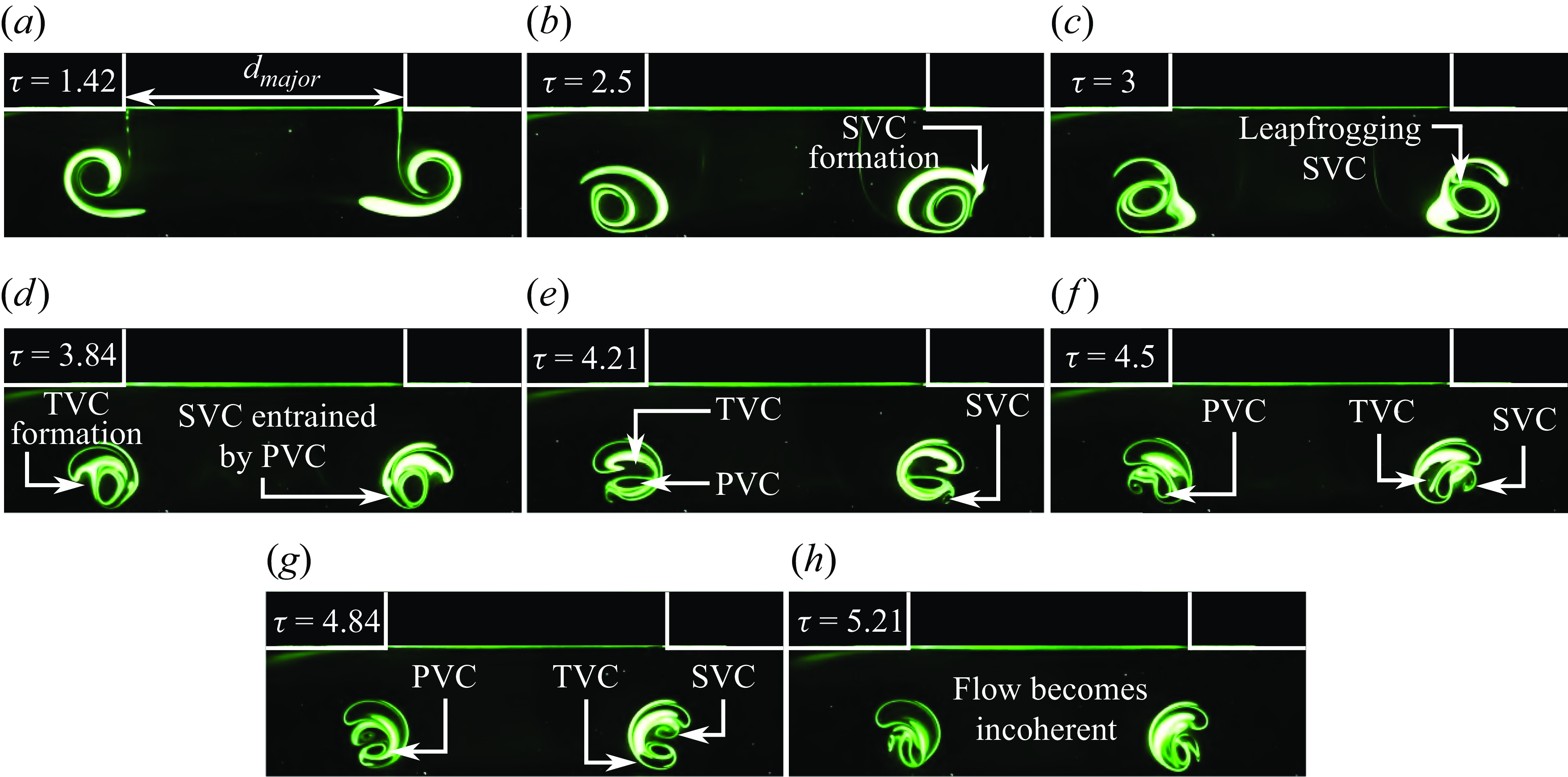
Figure 16. Instantaneous PLIF visualisations along the major plane of the $AR=2$
EVR colliding with the wall at the quarter-cycle location.
$AR=2$
EVR colliding with the wall at the quarter-cycle location.
The collision behaviour along the minor plane as shown in figure 17 paints a completely different picture, as far as confinement effects are concerned. Firstly, the timings reveal that the initial collision flow stages along the minor plane lag significantly behind those taking place along the major plane seen in figure 16 previously. Hence, it can be deduced that the primary EVR collides with the flat wall non-uniformly, as predicted in figure 4(b)(i) earlier. As such, the SVCs are expected to form and interact with PVCs non-uniformly. This would account for the differences seen in the SVC behaviour between the major and minor planes at this location. Take, for instance, figures 16(e)–16(g), which show the SVCs entangling around the PVCs along the major plane, while those observed along the minor plane in figures 17(d)–17(f) are obstructed by the water tank wall as part of the confinement effects. In fact, parts of the SVCs actually lead to boundary layer separations and wall vortices along the orificewall when they collide with it, as can be appreciated in figure 17(g), while other parts manage to be entrained by the PVCs. Figure 17(h) further reveals that the PVCs bulge and the entire flow field evolves into an incoherent state very rapidly.
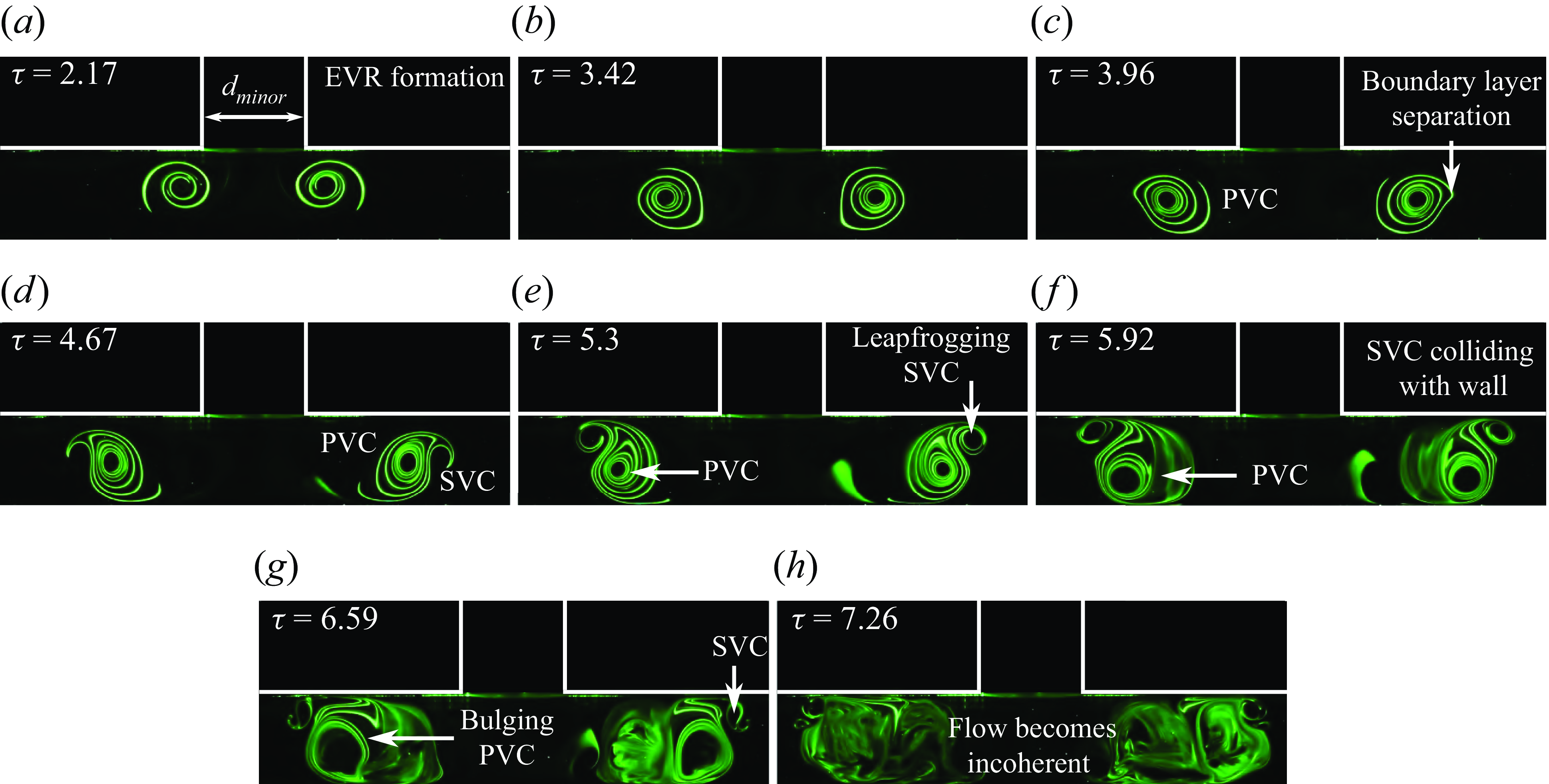
Figure 17. Instantaneous PLIF visualisations along the minor plane of the $AR=2$
EVR colliding with the wall at the quarter-cycle location.
$AR=2$
EVR colliding with the wall at the quarter-cycle location.
3.2. The case of AR = 4 elliptic vortex-ring collisions
This section will now describe the collision outcomes for the $AR=4$
EVR. Due to bifurcation behaviour, there are only two distinct collision locations identified. Nevertheless, the availability of these experimental results allows a better understanding of how increasing the EVR aspect ratio may affect the vortex dynamics of the collisions.
$AR=4$
EVR. Due to bifurcation behaviour, there are only two distinct collision locations identified. Nevertheless, the availability of these experimental results allows a better understanding of how increasing the EVR aspect ratio may affect the vortex dynamics of the collisions.
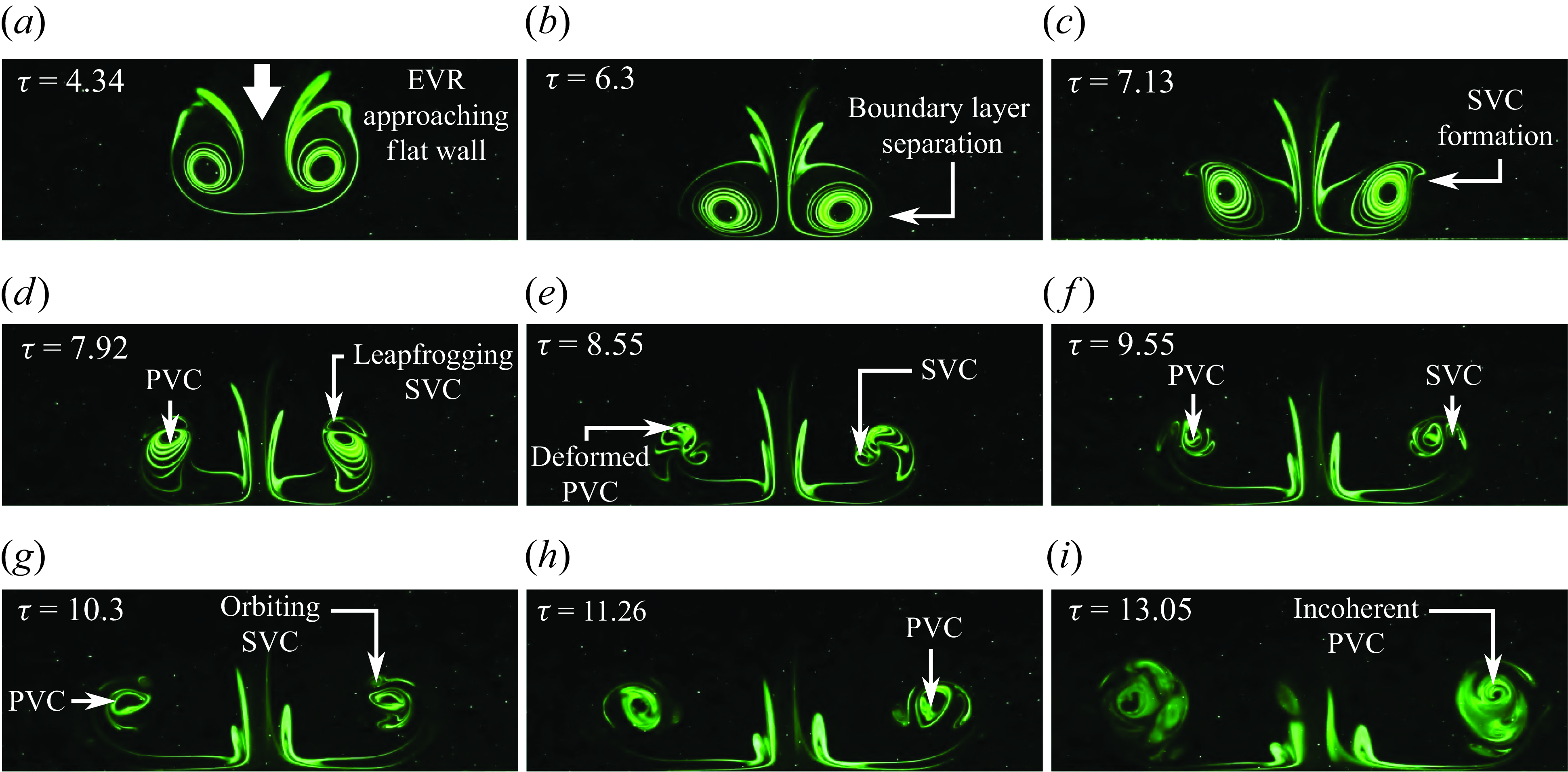
Figure 18. Instantaneous PLIF visualisations along the major plane of the $AR=4$
EVR colliding with the wall at the half-cycle location.
$AR=4$
EVR colliding with the wall at the half-cycle location.
3.2.1. Half-cycle collision behaviour
Figure 18 (see supplementary movie 9) shows the collision behaviours along the major plane and the initial collision stages are reminiscent of what has been observed for its $AR=2$
counterpart in figures 18(a)–18(d). Thereafter, however, the effects of aspect ratio certainly come into play, since the radii of curvature of the EVR segments at the major-diameter ends will be much smaller with accompanying higher induced velocities. Consequently, the rebounding effects are stronger along the major plane for the
$AR=2$
counterpart in figures 18(a)–18(d). Thereafter, however, the effects of aspect ratio certainly come into play, since the radii of curvature of the EVR segments at the major-diameter ends will be much smaller with accompanying higher induced velocities. Consequently, the rebounding effects are stronger along the major plane for the $AR=4$
EVR with the PVCs eventually rebounding to a greater distance away from the flat wall. This also means that only SVCs are formed since the PVCs are too high above the wall to induce another boundary layer separation for TVC formations. Furthermore, larger vortex-stretching effects are expected for the
$AR=4$
EVR with the PVCs eventually rebounding to a greater distance away from the flat wall. This also means that only SVCs are formed since the PVCs are too high above the wall to induce another boundary layer separation for TVC formations. Furthermore, larger vortex-stretching effects are expected for the $AR=4$
EVR due to its greater non-uniformity along its vortex filament and this is indeed reflected in the faster diminishing physical vortex-core sizes seen in figures 18(c)–18(h), as opposed to figures 12(c)–12(g). Additionally, SVC behaviour in figure 12 is very different from that in figure 18, as the latter only shows them entangling around the PVCs instead of forming vortexdipoles. Furthermore, there is no evidence of additional vortex structures found crossing the major plane near the end of the
$AR=4$
EVR due to its greater non-uniformity along its vortex filament and this is indeed reflected in the faster diminishing physical vortex-core sizes seen in figures 18(c)–18(h), as opposed to figures 12(c)–12(g). Additionally, SVC behaviour in figure 12 is very different from that in figure 18, as the latter only shows them entangling around the PVCs instead of forming vortexdipoles. Furthermore, there is no evidence of additional vortex structures found crossing the major plane near the end of the $AR=4$
EVR collision at this location, as shown by figure 18(i), unlike what had been observed for the
$AR=4$
EVR collision at this location, as shown by figure 18(i), unlike what had been observed for the $AR=2$
EVR collision in figures 12(i). Instead, the PVC and SVC simply entwine around one another for the higher aspect ratio EVR, and grow bulbous before flow incoherence sets in.
$AR=2$
EVR collision in figures 12(i). Instead, the PVC and SVC simply entwine around one another for the higher aspect ratio EVR, and grow bulbous before flow incoherence sets in.
Collision outcomes along the minor plane are now presented in figure 19 (see supplementary movie 10) and the behaviour largely resembles that observed for the corresponding $AR=2$
EVR collision along the same plane in figure 14. Unlike the major plane, the
$AR=2$
EVR collision along the same plane in figure 14. Unlike the major plane, the $AR=4$
PVCs actually interact with the stopping vortex cores along the minor plane prior to the collision with the wall. This is likely due to both the confinement effects and the induced velocities by the EVR segments at the major diameters (see figure 4
c(ii)) now being sufficiently high to draw the stopping vortex cores towards them. As the rotational senses are the same as typical SVCs seen earlier, the stopping vortex cores behave like them, leapfrogging over and entangling around the PVCs shortly after the collision. The same happens for the SVCs and TVCs formed later on, until they eventually become incoherent. Interestingly, additional vortex structures crossing the minor plane can be found near the orificewall in figure 19(h). Initially, they were thought of as extraneous dye or incoherent vortex structures as they appear afterthe flow becomes incoherent. However, repeated experiments consistently show that these vortex structures show up quite symmetrically along the collision axis. Considering the similarity between these vortex structures and the additional vortex structures crossing the minor plane in figure 14(i), they are postulated to result from colliding vortex loops as well.
$AR=4$
PVCs actually interact with the stopping vortex cores along the minor plane prior to the collision with the wall. This is likely due to both the confinement effects and the induced velocities by the EVR segments at the major diameters (see figure 4
c(ii)) now being sufficiently high to draw the stopping vortex cores towards them. As the rotational senses are the same as typical SVCs seen earlier, the stopping vortex cores behave like them, leapfrogging over and entangling around the PVCs shortly after the collision. The same happens for the SVCs and TVCs formed later on, until they eventually become incoherent. Interestingly, additional vortex structures crossing the minor plane can be found near the orificewall in figure 19(h). Initially, they were thought of as extraneous dye or incoherent vortex structures as they appear afterthe flow becomes incoherent. However, repeated experiments consistently show that these vortex structures show up quite symmetrically along the collision axis. Considering the similarity between these vortex structures and the additional vortex structures crossing the minor plane in figure 14(i), they are postulated to result from colliding vortex loops as well.
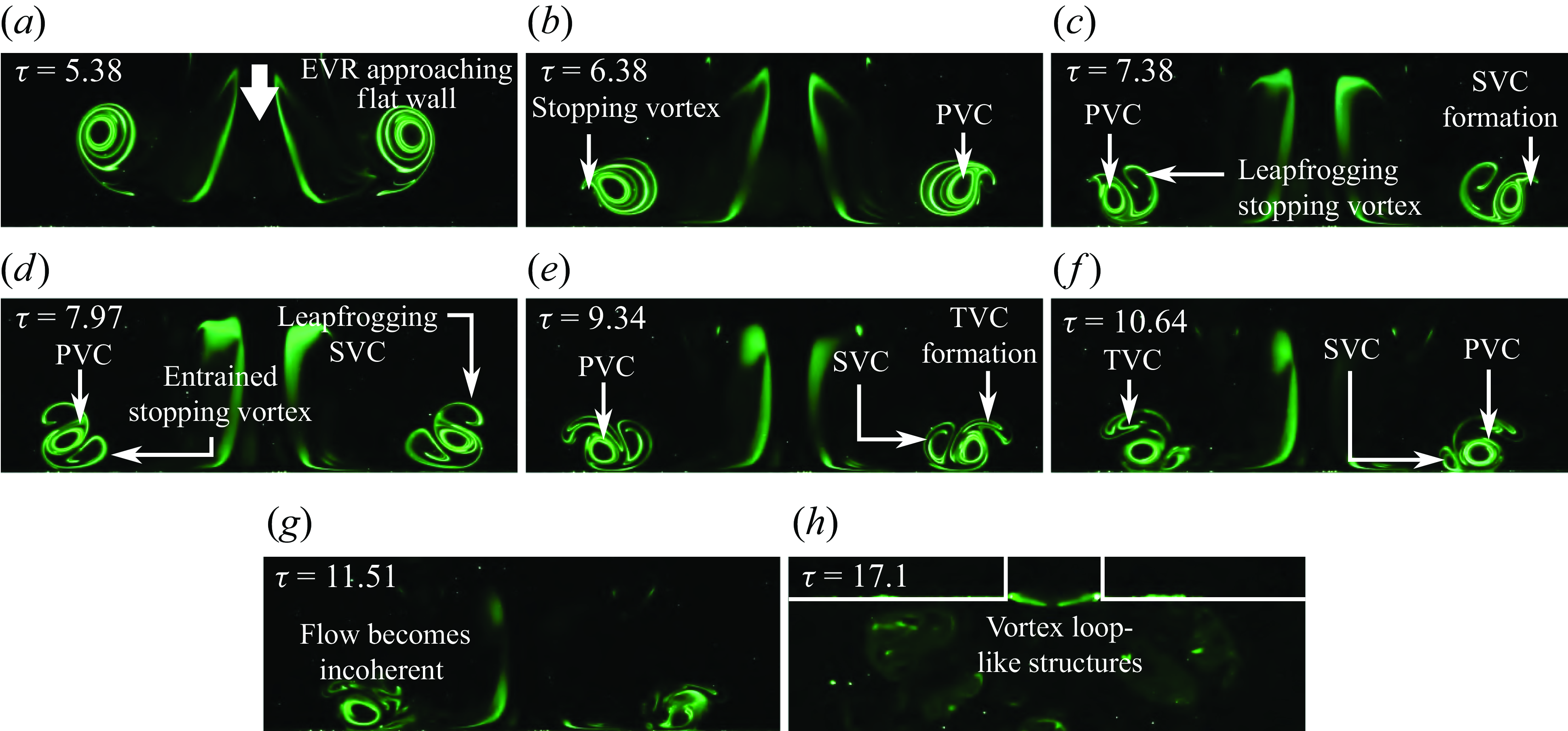
Figure 19. Instantaneous PLIF visualisations along the minor plane of the $AR=4$
EVR colliding with the wall at the half-cycle location.
$AR=4$
EVR colliding with the wall at the half-cycle location.
3.2.2. Quarter-cycle collision behaviour
Finally, collision behaviour at quarter-cycle location along both planes is presented in figures 20 and 21. Along the major plane, the general behaviours of both $AR=2$
and 4 EVR collisions at the same quarter-cycle location are similar. However, increasing the aspect ratio leads to faster entrainment of SVCs and TVCs and their entanglement around the PVCs after the collision. Furthermore, the rapid pace at which their physical sizes reduce during the vortex entanglements demonstrates that vortex-stretching levels are significantly higher at this location. Certain flow behaviour along the minor plane deviates from that seen for the
$AR=2$
and 4 EVR collisions at the same quarter-cycle location are similar. However, increasing the aspect ratio leads to faster entrainment of SVCs and TVCs and their entanglement around the PVCs after the collision. Furthermore, the rapid pace at which their physical sizes reduce during the vortex entanglements demonstrates that vortex-stretching levels are significantly higher at this location. Certain flow behaviour along the minor plane deviates from that seen for the $AR=2$
EVR, where the stopping vortex plays an even more important role in the vortex dynamics than what had been observed in figure 19 at half-cycle location previously. Take, for instance, figures 21(a)–21(b), shortly after the EVR has been formed, the stopping vortex cores are entrained by the PVCs from within rather than along its outer periphery. As the stopping vortex cores entangle around the PVCs, the latter destabilise and become bulbous within the confined environment. This indicates vortexcompression along this plane. While the incoherent PVCs still cause SVCs to form off the wall, they appear weak and incoherent.
$AR=2$
EVR, where the stopping vortex plays an even more important role in the vortex dynamics than what had been observed in figure 19 at half-cycle location previously. Take, for instance, figures 21(a)–21(b), shortly after the EVR has been formed, the stopping vortex cores are entrained by the PVCs from within rather than along its outer periphery. As the stopping vortex cores entangle around the PVCs, the latter destabilise and become bulbous within the confined environment. This indicates vortexcompression along this plane. While the incoherent PVCs still cause SVCs to form off the wall, they appear weak and incoherent.
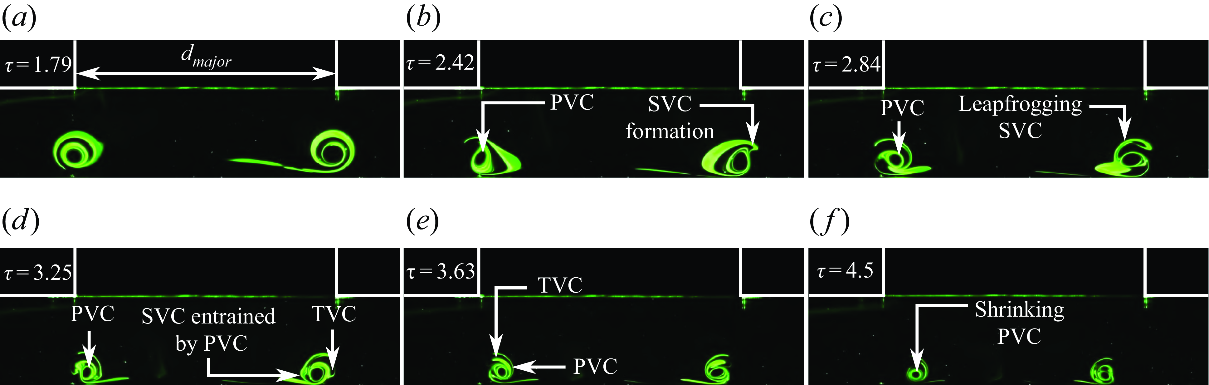
Figure 20. Instantaneous PLIF visualisations along the major plane of the $AR=4$
EVR colliding with the wall at the quarter-cycle location.
$AR=4$
EVR colliding with the wall at the quarter-cycle location.
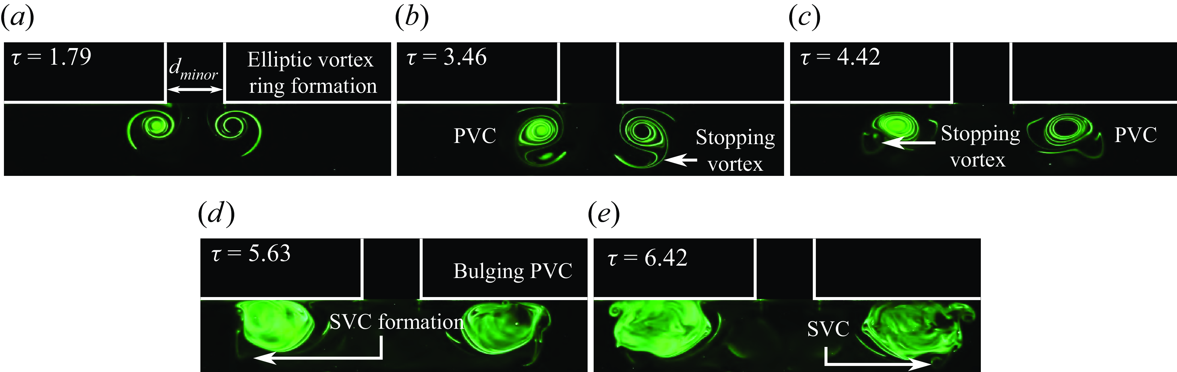
Figure 21. Instantaneous PLIF visualisations along the minor plane of the $AR=4$
EVR colliding with the wall at the quarter-cycle location.
$AR=4$
EVR colliding with the wall at the quarter-cycle location.
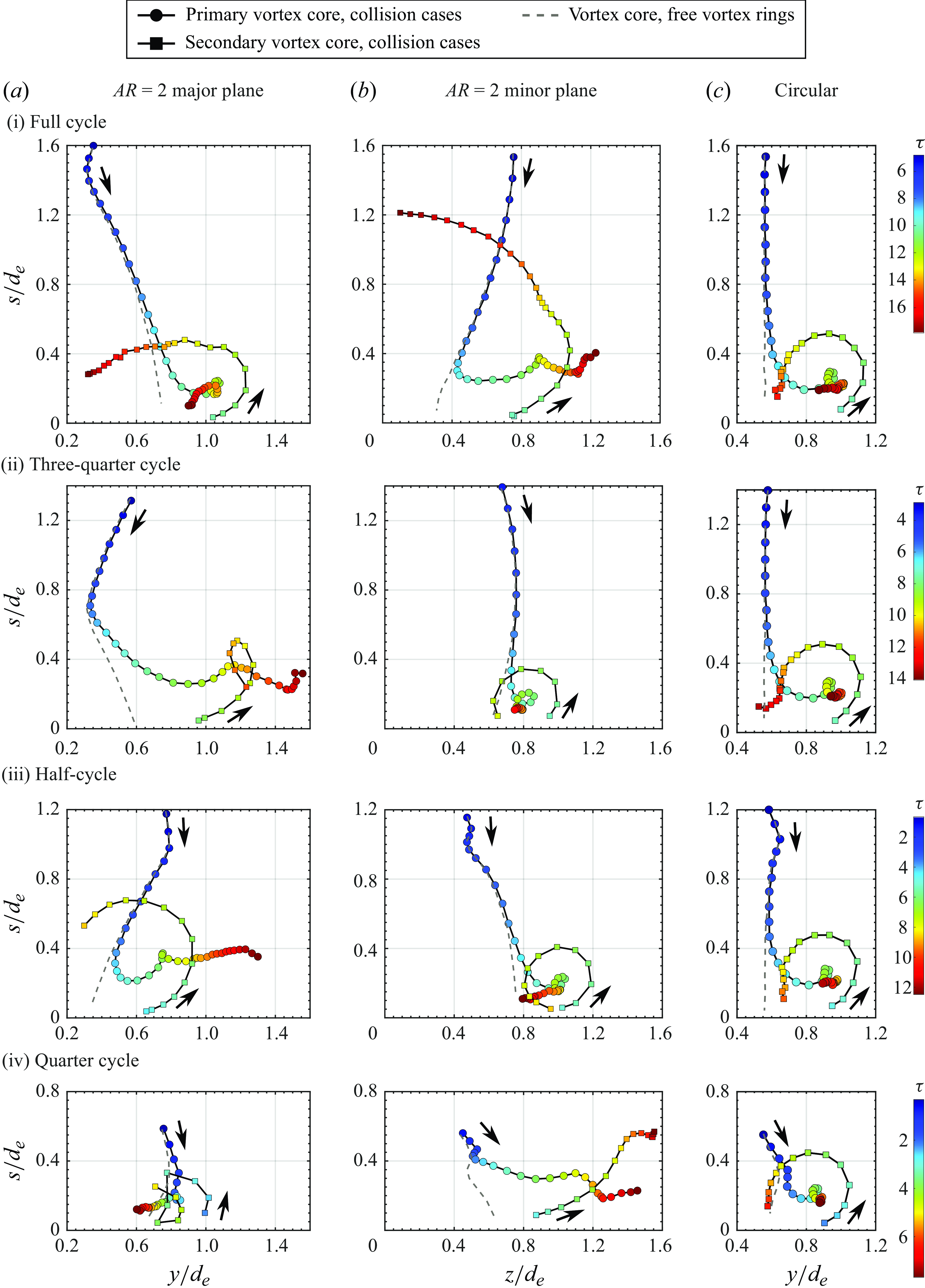
Figure 22. The PVC and SVC trajectories for $AR=2$
EVR (a) major plane, (b) minor plane and (c) CVR associated with collisions at (i) full-cycle, (ii) three-quarter cycle, (iii) half-cycle and (iv) quarter-cycle locations. Vortex-core trajectories for freely translating
$AR=2$
EVR (a) major plane, (b) minor plane and (c) CVR associated with collisions at (i) full-cycle, (ii) three-quarter cycle, (iii) half-cycle and (iv) quarter-cycle locations. Vortex-core trajectories for freely translating $AR=2$
EVR and CVR are included for comparisons.
$AR=2$
EVR and CVR are included for comparisons.
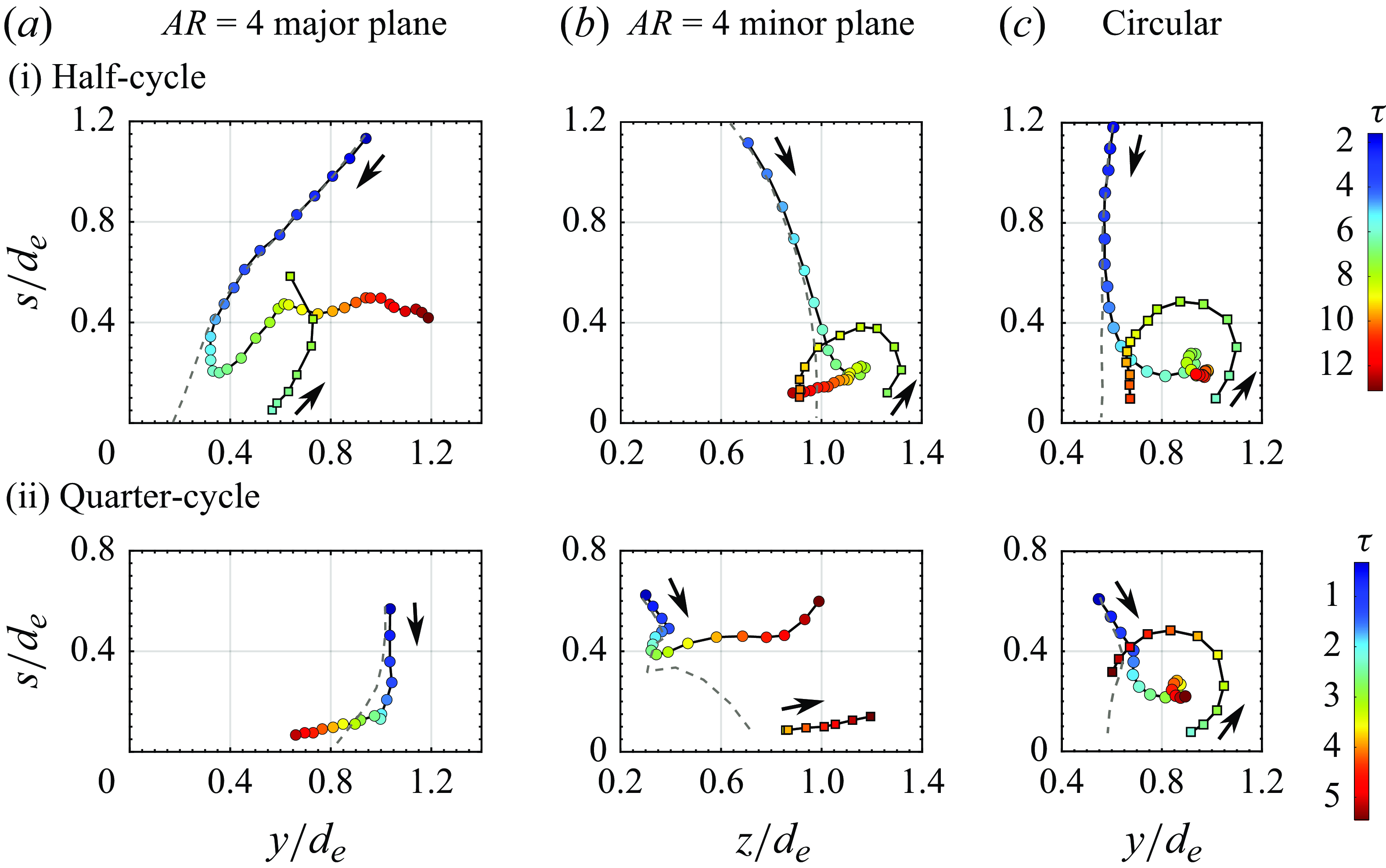
Figure 23. The PVC and SVC trajectories for $AR=4$
EVR (a) major plane, (b) minor plane and (c) CVR associated with collisions at (i) half-cycle and (ii) quarter-cycle locations. Vortex-core trajectories for freely translating
$AR=4$
EVR (a) major plane, (b) minor plane and (c) CVR associated with collisions at (i) half-cycle and (ii) quarter-cycle locations. Vortex-core trajectories for freely translating $AR=4$
EVR and CVR are included for comparisons.
$AR=4$
EVR and CVR are included for comparisons.
3.3. Vortex-core trajectories
To better inspect the behaviours of vortex cores, their trajectories are extracted and presented in this section. The vortex-core centre coordinates were estimated using (2.2). Trajectories of PVCs and SVCs for $AR=2$
and 4 EVRs for all collision locations are presented in figures 22 and 23, where the results for TVCs are omitted here as their strengths are usually too weak to estimate their core locations reliably. Additionally, markers for the vortex-core locations are colourtagged according to non-dimensional timings to provide temporal information, where the time interval between adjacent markers is
$AR=2$
and 4 EVRs for all collision locations are presented in figures 22 and 23, where the results for TVCs are omitted here as their strengths are usually too weak to estimate their core locations reliably. Additionally, markers for the vortex-core locations are colourtagged according to non-dimensional timings to provide temporal information, where the time interval between adjacent markers is $\mathrm{\Delta }\tau =0.32$
. Finally, to allow better comparisons, trajectories of free translating
$\mathrm{\Delta }\tau =0.32$
. Finally, to allow better comparisons, trajectories of free translating $AR=2$
and 4 EVRs are also included as dashedlines to better highlight the influence of wall on the axis-switching process. Meanwhile, vortex-core trajectories of CVRs colliding with the wall at the same locations as those used for
$AR=2$
and 4 EVRs are also included as dashedlines to better highlight the influence of wall on the axis-switching process. Meanwhile, vortex-core trajectories of CVRs colliding with the wall at the same locations as those used for $AR=2$
and 4 EVRs are presented and compared with those produced by EVR-based collisions. Note that the vortex-core locations on both sides of the collision symmetry plane were averaged to minimise uncertainty, similar to the procedure adopted for the freely translating EVR core trajectories. Last but not least,
$AR=2$
and 4 EVRs are presented and compared with those produced by EVR-based collisions. Note that the vortex-core locations on both sides of the collision symmetry plane were averaged to minimise uncertainty, similar to the procedure adopted for the freely translating EVR core trajectories. Last but not least, $s/d_{\textit{e}}=0$
is set along the wall surface to better appreciate how far the various vortex cores are from the wall.
$s/d_{\textit{e}}=0$
is set along the wall surface to better appreciate how far the various vortex cores are from the wall.
To begin, figure 22(i) shows the drastically different trajectories not only between the major and minor planes for $AR=2$
EVR collision at full-cycle location, but also when compared with the CVR collision. The PVC trajectory for CVR collisions is actually relatively insensitive to the exact collision location, as can be discerned from figures 22(c)(i)–22(iii). For the EVR collisions, however, not only do the PVCs move away from and towards the collision axis along the major and minor planes, respectively, there are also huge differences in the SVC trajectories. Along the major plane, the PVC trajectory deviates from that under freely translating conditions from approximately
$AR=2$
EVR collision at full-cycle location, but also when compared with the CVR collision. The PVC trajectory for CVR collisions is actually relatively insensitive to the exact collision location, as can be discerned from figures 22(c)(i)–22(iii). For the EVR collisions, however, not only do the PVCs move away from and towards the collision axis along the major and minor planes, respectively, there are also huge differences in the SVC trajectories. Along the major plane, the PVC trajectory deviates from that under freely translating conditions from approximately $s/d_{\textit{e}}=0.8$
onwards but would eventually move towards the collision axis later. In contrast, the SVC moves significantly more towards the collision axis and away from the PVC after the leapfrogging process. Along the minor plane, while the PVC trajectory only deviates from that under freely translating conditions from approximately
$s/d_{\textit{e}}=0.8$
onwards but would eventually move towards the collision axis later. In contrast, the SVC moves significantly more towards the collision axis and away from the PVC after the leapfrogging process. Along the minor plane, while the PVC trajectory only deviates from that under freely translating conditions from approximately $s/d_{\textit{e}}=0.4$
onwards, it moves away from the collision axis after encountering the wall up to a distance of
$s/d_{\textit{e}}=0.4$
onwards, it moves away from the collision axis after encountering the wall up to a distance of $z/d_{\textit{e}}=1.2$
. On the other hand, SVC moves not only towards the collision axis, but also away from the wall in the upstream direction up to
$z/d_{\textit{e}}=1.2$
. On the other hand, SVC moves not only towards the collision axis, but also away from the wall in the upstream direction up to $s/d_{\textit{e}}=1.2$
. Interestingly, the SVC also undergoes a momentary acceleration as it moves upstream, which is not observed along the major plane or in CVR-based collision and indicative of longer-lasting vortical activities than the CVR-based collision. With these preceding behaviours, it is telling that the EVR diameter increases earlier but less along the major plane, but later and more along the minor plane. This can be understood if one refers to figure 4(b) earlier, where the increase in EVR diameter due to the collision is limited by the inwards motion of the vortex-ring segment along the major plane, while the increase in EVR diameter due to the collision is further enhanced by the outwards motion of the vortex-ring segment along the minor plane.
$s/d_{\textit{e}}=1.2$
. Interestingly, the SVC also undergoes a momentary acceleration as it moves upstream, which is not observed along the major plane or in CVR-based collision and indicative of longer-lasting vortical activities than the CVR-based collision. With these preceding behaviours, it is telling that the EVR diameter increases earlier but less along the major plane, but later and more along the minor plane. This can be understood if one refers to figure 4(b) earlier, where the increase in EVR diameter due to the collision is limited by the inwards motion of the vortex-ring segment along the major plane, while the increase in EVR diameter due to the collision is further enhanced by the outwards motion of the vortex-ring segment along the minor plane.
As the collision location draws nearer to three-quarter-cycle location in figure 22(ii), EVR diameters along both planes just prior to the collisions show some discrepancies, despite the expectation that they should be similar based on the freely translating EVR presented in figure 4(b)(iii). However, this can be attributed to the adverse pressure gradient imposed by the wall, which is absent in the freely translating $AR=2$
EVR scenario. Then, PVC trajectory along the major plane deviates from that under freely translating condition also at around
$AR=2$
EVR scenario. Then, PVC trajectory along the major plane deviates from that under freely translating condition also at around $s/d_{\textit{e}}=0.8$
onwards. In particular, the PVC moves away from the collision axis more significantly to approximately
$s/d_{\textit{e}}=0.8$
onwards. In particular, the PVC moves away from the collision axis more significantly to approximately $y/d_{\textit{e}}=1.6$
, despite the formation of SVC half-way through. Note that the SVC moves appreciably away from the collision axis after the leapfrogging process. Along the minor plane, the PVC trajectory resembles that of CVR-based collision in figure 22(c)(ii), while deviating from that under the freely translating condition at only around
$y/d_{\textit{e}}=1.6$
, despite the formation of SVC half-way through. Note that the SVC moves appreciably away from the collision axis after the leapfrogging process. Along the minor plane, the PVC trajectory resembles that of CVR-based collision in figure 22(c)(ii), while deviating from that under the freely translating condition at only around $s/d_{\textit{e}}=0.5$
onwards. Essentially, this means that the EVR diameter grows substantially along the major plane, while remaining much more constrained along the minor plane. Referring to figure 4(b) again, one can tell that the vortex-ring segment along the major plane at this stage incurs outwards motions as it transits to the full-cycle stage. Together with the collision which will cause an increase in the EVR diameter in the first place, this inevitably leads to a significant diameter growth along the major plane. On the other hand, figure 4(b) shows that vortex-ring segments along the minor plane at this stage are moving inwards as part of the axis-switching behaviour and, as such, negate much of the EVR diameter increase along this plane and leads to a situation where the PVC almost stays stationary.
$s/d_{\textit{e}}=0.5$
onwards. Essentially, this means that the EVR diameter grows substantially along the major plane, while remaining much more constrained along the minor plane. Referring to figure 4(b) again, one can tell that the vortex-ring segment along the major plane at this stage incurs outwards motions as it transits to the full-cycle stage. Together with the collision which will cause an increase in the EVR diameter in the first place, this inevitably leads to a significant diameter growth along the major plane. On the other hand, figure 4(b) shows that vortex-ring segments along the minor plane at this stage are moving inwards as part of the axis-switching behaviour and, as such, negate much of the EVR diameter increase along this plane and leads to a situation where the PVC almost stays stationary.
Moving on to the half-cycle location in figure 22(iii), the PVC trajectory along the major plane does not deviate from that under the freely translating condition until around $s/d_{\textit{e}}=0.6$
onwards, where it moves away from the collision axis substantially up to around
$s/d_{\textit{e}}=0.6$
onwards, where it moves away from the collision axis substantially up to around $y/d_{\textit{e}}=1.3$
after the collision. The SVC trajectory shows a circular-arc-like leapfrogging process as it moves significantly upstream to almost
$y/d_{\textit{e}}=1.3$
after the collision. The SVC trajectory shows a circular-arc-like leapfrogging process as it moves significantly upstream to almost $s/d_{\textit{e}}=0.7$
, before it translates back downstream and towards the collision axis. Along the minor plane, the PVC trajectory differs from that under freely translating conditions from approximately
$s/d_{\textit{e}}=0.7$
, before it translates back downstream and towards the collision axis. Along the minor plane, the PVC trajectory differs from that under freely translating conditions from approximately $s/d_{\textit{e}}=0.8$
and upon colliding with the wall, moves towards the collision axis moderately. The leapfrogging and subsequent behaviour of the SVC resemble those ofthe corresponding CVR collision. These trajectories can again be understood from figure 4(b)(ii), where the vortex-ring segments along the major plane are undergoing both outwards and forward motions at this location. In particular, the collision accentuates the outwards motion due to the accompanying vortex-ring diameter expansion and would account for the significant PVC movement away from the collision axis seen previously. On the other hand, the vortex-ring segments along the minor plane are not experiencing any significant inwards or outwards motion tendencies, as shown in figure 4(b)(ii). Instead, these vortex-ring segments experience forward motion which would reduce the extent to which the vortex-ring diameter could expand during the collision. In fact, it is conceivable that the adverse pressure gradient produced by the presence of the wall leads to earlier flow transitions that see the earlier initiation of inwards motion like that observed for the same plane at three-quarter-cycle location, and would explain the moderate movement of the PVC towards the collision axis.
$s/d_{\textit{e}}=0.8$
and upon colliding with the wall, moves towards the collision axis moderately. The leapfrogging and subsequent behaviour of the SVC resemble those ofthe corresponding CVR collision. These trajectories can again be understood from figure 4(b)(ii), where the vortex-ring segments along the major plane are undergoing both outwards and forward motions at this location. In particular, the collision accentuates the outwards motion due to the accompanying vortex-ring diameter expansion and would account for the significant PVC movement away from the collision axis seen previously. On the other hand, the vortex-ring segments along the minor plane are not experiencing any significant inwards or outwards motion tendencies, as shown in figure 4(b)(ii). Instead, these vortex-ring segments experience forward motion which would reduce the extent to which the vortex-ring diameter could expand during the collision. In fact, it is conceivable that the adverse pressure gradient produced by the presence of the wall leads to earlier flow transitions that see the earlier initiation of inwards motion like that observed for the same plane at three-quarter-cycle location, and would explain the moderate movement of the PVC towards the collision axis.
For the quarter-cycle location shown in figure 22(iv), confinement effects have much larger effects on the PVC and SVC trajectories of EVR along both planes than their CVR counterparts. Take, for instance, figure 22(a)(iv), which shows a highly constrained collision outcome where both PVC and SVC along the major plane show very limited movements just above the wall after the collision. The SVC along this plane exhibits what seems like a second leapfrogging, as the PVC moves slightly towards the collision axis close to the end of the collision process. On the other hand, figure 22(b)(iv) portrays an outcome where both the PVC and SVC move significantly away from the collision axis along the minor plane. The PVC trajectory for the collision scenario differs greatly from that associated with its freely translating counterpart almost immediately after it is formed, with the former moving very rapidly and furthest away from the collision axis seen so far. Even more intriguing is the SVC trajectory, which sees it moving above the PVC and registering the furthest distance away from the collision axis when the collision process ends. To understand this, figure 4(b)(i) shows that the vortex-ring segments should be experiencing inwards motion and while the collision produces opposite effects. Hence, that explains why movements of the PVC along the major plane remain relatively limited, with a slight movement towards the collision axis. In contrast, however, figure 4(b)(ii) shows that the vortex-ring segments should be experiencing outwards motion along minor plane at this location, which added to the vortex-ring diameter increment accompanying the collision would produce an outcome observed along the minor plane described above.
Figures 23 and 24 present the trajectory results for $AR=4$
EVR collisions and their comparisons with
$AR=4$
EVR collisions and their comparisons with $AR=2$
EVR collisions at the corresponding collision locations. At half-cycle location, PVC and SVC trajectories are quite similar between
$AR=2$
EVR collisions at the corresponding collision locations. At half-cycle location, PVC and SVC trajectories are quite similar between $AR=2$
and 4 EVR collisions along the major and minor planes, despite the
$AR=2$
and 4 EVR collisions along the major and minor planes, despite the $AR=4$
PVC moving significantly away from the collision axis along the major plane and rebounding higher. Coming to the quarter-cycle location, the trajectory behaviours of
$AR=4$
PVC moving significantly away from the collision axis along the major plane and rebounding higher. Coming to the quarter-cycle location, the trajectory behaviours of $AR=4$
EVRs resemble those seen for the
$AR=4$
EVRs resemble those seen for the $AR=2$
EVR at the same location as well, especially that along the major plane. Along the minor plane,
$AR=2$
EVR at the same location as well, especially that along the major plane. Along the minor plane, $AR=2$
PVC and SVC move further away from the collision axis than their
$AR=2$
PVC and SVC move further away from the collision axis than their $AR=2$
counterparts. To sum up, increasing the aspect ratio from 2 to 4 does not fundamentally alter the trajectory dynamics. Rather, it mainly affects how the vortex cores move from the collision axis, which is due to the different axis-switching states and induced velocities.
$AR=2$
counterparts. To sum up, increasing the aspect ratio from 2 to 4 does not fundamentally alter the trajectory dynamics. Rather, it mainly affects how the vortex cores move from the collision axis, which is due to the different axis-switching states and induced velocities.
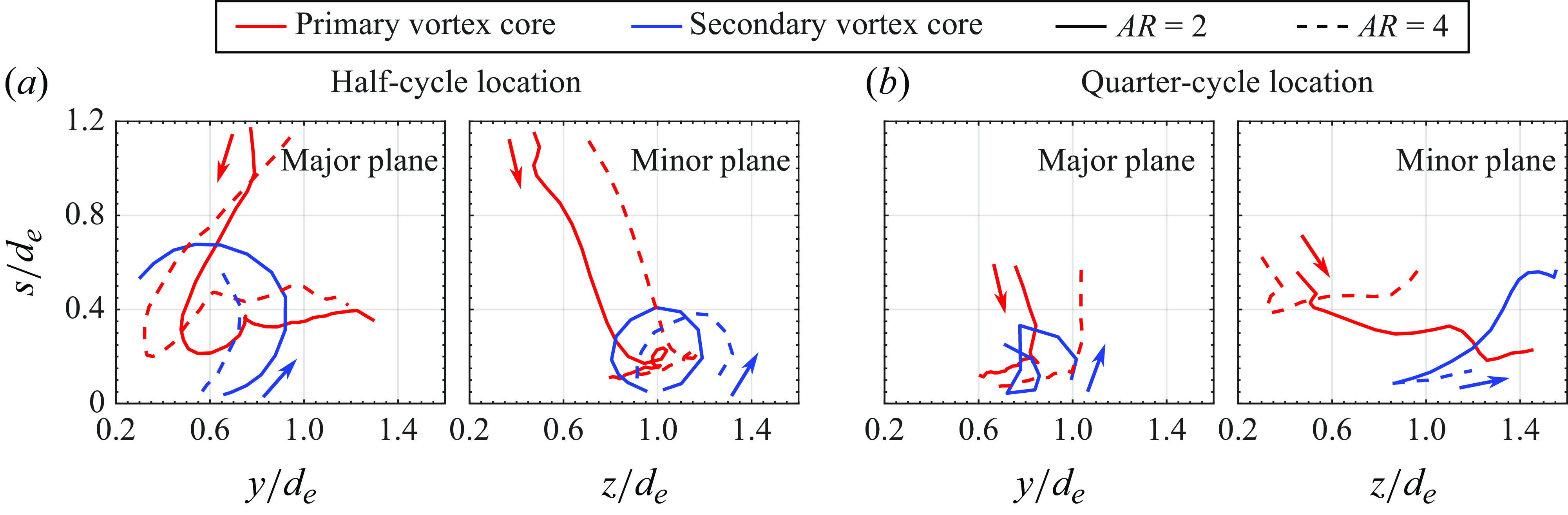
Figure 24. Comparisons of PVC and SVC trajectories for $AR=2$
and
$AR=2$
and $AR=4$
EVRs collisions at (a) half-cycle and (b) quarter-cycle locations.
$AR=4$
EVRs collisions at (a) half-cycle and (b) quarter-cycle locations.
The EVR diameters along major and minor planes, which are $y_c$
and
$y_c$
and $z_c$
, respectively, can be quantified from vortex-core trajectories as well. The temporal variations of EVR diameters can be showcased in the form of diameter ratio
$z_c$
, respectively, can be quantified from vortex-core trajectories as well. The temporal variations of EVR diameters can be showcased in the form of diameter ratio $\gamma =y_{c}/z_{c}$
, as it can better reflect the vortex filament motions in different directions. Figure 25 illustrates the temporal developments of
$\gamma =y_{c}/z_{c}$
, as it can better reflect the vortex filament motions in different directions. Figure 25 illustrates the temporal developments of $\gamma$
at each collision location for
$\gamma$
at each collision location for $AR=2$
and 4 EVRs and their comparisons with freely translating EVRs, where vertical dashed lines stand for the time instances when the SVCs form. For the
$AR=2$
and 4 EVRs and their comparisons with freely translating EVRs, where vertical dashed lines stand for the time instances when the SVCs form. For the $AR=2$
freely translating EVRs,
$AR=2$
freely translating EVRs, $\gamma$
first decreases to approximately 0.4, which impliesthat the current aspect ratio has exceeded the initial value of 2. Later,
$\gamma$
first decreases to approximately 0.4, which impliesthat the current aspect ratio has exceeded the initial value of 2. Later, $\gamma$
increases to a maximum value higher than 2 as well. Interestingly, the presence of the wall does not alter the developing trends of
$\gamma$
increases to a maximum value higher than 2 as well. Interestingly, the presence of the wall does not alter the developing trends of $\gamma$
, despite figures 22 and 23 showing varied core trajectories after the primary EVR collides with the wall. Take the
$\gamma$
, despite figures 22 and 23 showing varied core trajectories after the primary EVR collides with the wall. Take the $AR=2$
EVR collision at the three-quarter-cycle location as an example, the diameter ratio follows closely that of the freely translating EVR before collision. Although they diverge from each other after collision, the diameter ratio of the colliding EVR still follows an increasing trend similar to that of the freely translating EVR. This actually reinforces the notion that the motion of PVCs after collision are still subject to the influence of axisswitching. However, the change in diameter ratio after the collision is not as steep as that of freely translating EVRs and actually highlights the effects by the wall. Taking the
$AR=2$
EVR collision at the three-quarter-cycle location as an example, the diameter ratio follows closely that of the freely translating EVR before collision. Although they diverge from each other after collision, the diameter ratio of the colliding EVR still follows an increasing trend similar to that of the freely translating EVR. This actually reinforces the notion that the motion of PVCs after collision are still subject to the influence of axisswitching. However, the change in diameter ratio after the collision is not as steep as that of freely translating EVRs and actually highlights the effects by the wall. Taking the $AR=2$
EVR collision at three-quarter-cycle location as an example again, although the PVC along the major plane spreads outwards, its motion is decelerated considerably by the no-slip condition imposed by the wall. Meanwhile, the PVC along the minor plane is restricted by the wall and shows very little inwards motion as well. As a result, diameter ratio changes are more gradual for the collision scenarios.
$AR=2$
EVR collision at three-quarter-cycle location as an example again, although the PVC along the major plane spreads outwards, its motion is decelerated considerably by the no-slip condition imposed by the wall. Meanwhile, the PVC along the minor plane is restricted by the wall and shows very little inwards motion as well. As a result, diameter ratio changes are more gradual for the collision scenarios.
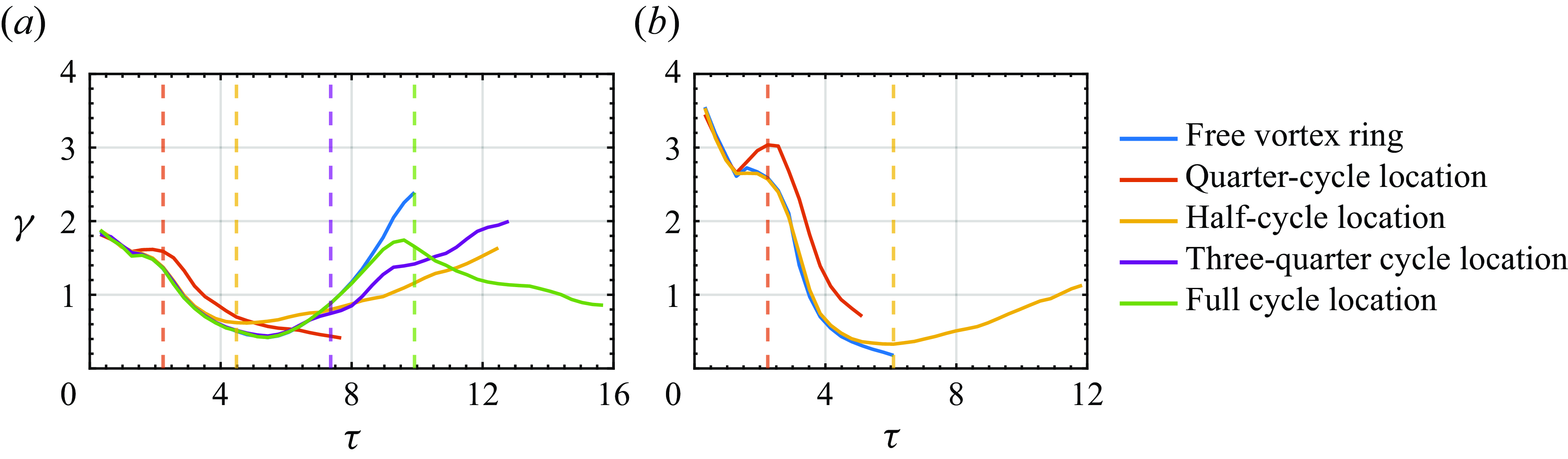
Figure 25. Temporal evolution of the primary vortex-ring diameter ratio of (a) $AR=2$
EVR collisions and (b)
$AR=2$
EVR collisions and (b) $AR=4$
EVR collisions. Vertical lines stand for the time instance when the SVCs are first formed.
$AR=4$
EVR collisions. Vertical lines stand for the time instance when the SVCs are first formed.
3.4. Vortex-core circulation
To better understand how the vortex-core circulation levels evolve during the collision processes, the circulation variations of all the test cases were calculated using (2.2) andare presented in figure 26. Corresponding results for freely translating vortex rings and CVR collisions are included to ease comparisons as well. For the freely translating $AR=2$
EVR shown in figure 26(a)(i), PVC circulation level along the major plane increases very rapidly upon formation until it reaches and fluctuates around a maximum level. Thereafter, however, it decreases steadily from around
$AR=2$
EVR shown in figure 26(a)(i), PVC circulation level along the major plane increases very rapidly upon formation until it reaches and fluctuates around a maximum level. Thereafter, however, it decreases steadily from around $\tau =4.5$
onwards until it reaches slightly lower than
$\tau =4.5$
onwards until it reaches slightly lower than $80\,\%$
of the peak circulation. As for that along the minor plane seen in figure 26(b)(i), the initial circulation changes during the EVR formation remain similar to that along the major plane. However, the decrease in circulation level once it hits the maximum from approximately
$80\,\%$
of the peak circulation. As for that along the minor plane seen in figure 26(b)(i), the initial circulation changes during the EVR formation remain similar to that along the major plane. However, the decrease in circulation level once it hits the maximum from approximately $\tau =1.5$
onwards is much more rapid, before it settles into a relatively steady level at just above
$\tau =1.5$
onwards is much more rapid, before it settles into a relatively steady level at just above $80\,\%$
of the peak circulation until around
$80\,\%$
of the peak circulation until around $\tau =7.5$
where it decreases gradually thereafter. For the freely translating CVR shown in figure 26(c)(i), the circulation decreases gradually while fluctuating about a negative linear trend after reaching a maximum level.
$\tau =7.5$
where it decreases gradually thereafter. For the freely translating CVR shown in figure 26(c)(i), the circulation decreases gradually while fluctuating about a negative linear trend after reaching a maximum level.
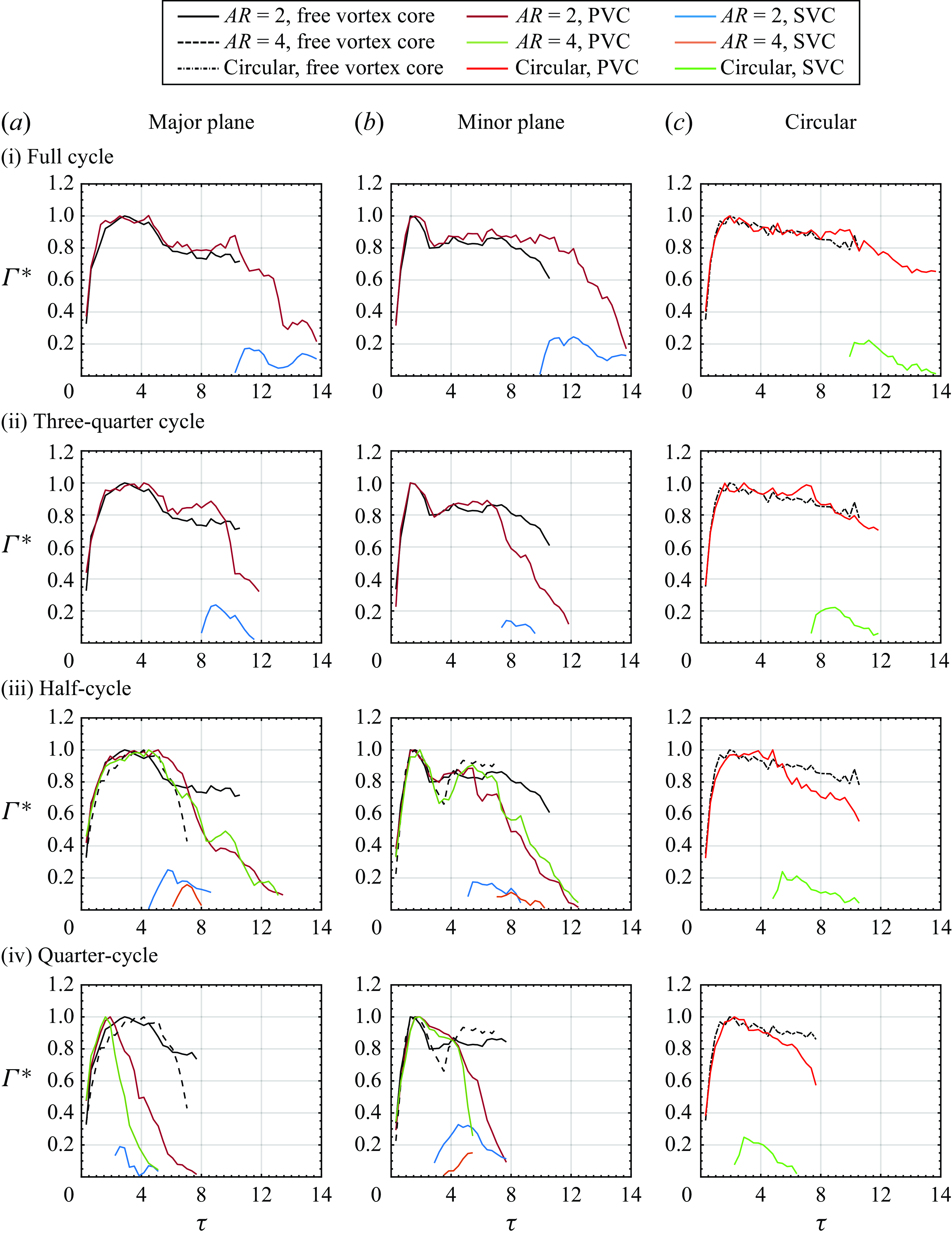
Figure 26. The PVC and SVC circulation variations for $AR=2$
EVR (a) major plane, (b) minor plane and (c) CVR associated with collisions at (i) full-cycle, (ii) three-quarter-cycle, (iii) half-cycle and (iv) quarter-cycle locations. Results for freely translating
$AR=2$
EVR (a) major plane, (b) minor plane and (c) CVR associated with collisions at (i) full-cycle, (ii) three-quarter-cycle, (iii) half-cycle and (iv) quarter-cycle locations. Results for freely translating $AR=2$
EVR and CVR are included for comparisons.
$AR=2$
EVR and CVR are included for comparisons.
With the freely translating vortex rings circulation behaviour established, results for $AR=2$
EVR colliding at each location shown in figures 26(i)–(iv) will now be discussed. Regardless of the exact collision location and plane, PVC circulation always incurs a momentary increase during the collision, before it subsequently decreases way below that of the freely translating EVR other than the full-cycle locations. This is very similar to the CVR collisions seen in figure 26(c) and represents an almost universal response of the PVC during the collisions. Interestingly, the general rate of decrease in the PVC circulation does not appear to vary significantly between major and minor planes, as well as different collision locations. This is unlike the case for CVR collision where the rate of circulation reduction increases as the collision occurs nearer to the orifice. The SVC circulation variations are quite similar to those exhibited by their PVC counterparts, in which the circulation level increases to a maximum value before decreasing thereafter. Most of the SVC circulations reach approximately
$AR=2$
EVR colliding at each location shown in figures 26(i)–(iv) will now be discussed. Regardless of the exact collision location and plane, PVC circulation always incurs a momentary increase during the collision, before it subsequently decreases way below that of the freely translating EVR other than the full-cycle locations. This is very similar to the CVR collisions seen in figure 26(c) and represents an almost universal response of the PVC during the collisions. Interestingly, the general rate of decrease in the PVC circulation does not appear to vary significantly between major and minor planes, as well as different collision locations. This is unlike the case for CVR collision where the rate of circulation reduction increases as the collision occurs nearer to the orifice. The SVC circulation variations are quite similar to those exhibited by their PVC counterparts, in which the circulation level increases to a maximum value before decreasing thereafter. Most of the SVC circulations reach approximately $20\,\%$
of the maximum PVC circulation. However, peak SVC circulation in figure 26(b)(iv) reaches approximately
$20\,\%$
of the maximum PVC circulation. However, peak SVC circulation in figure 26(b)(iv) reaches approximately $35\,\%$
of peak PVC circulation, which could be attributed to confinement effects.
$35\,\%$
of peak PVC circulation, which could be attributed to confinement effects.
The circulation variations of freely translating $AR=4$
EVR shown in figures 26(iii)–(iv) are quite different to its
$AR=4$
EVR shown in figures 26(iii)–(iv) are quite different to its $AR=2$
counterpart. Along the major plane, while the PVC circulation increases rapidly to a maximum after formation, it incurs a far more immediate and rapid decline than that of the
$AR=2$
counterpart. Along the major plane, while the PVC circulation increases rapidly to a maximum after formation, it incurs a far more immediate and rapid decline than that of the $AR=2$
EVR. Along the minor plane, however, the circulation does not settle into a relatively steady level after the sharp decline from the maximum level but, rather, it increases rapidly to approximately
$AR=2$
EVR. Along the minor plane, however, the circulation does not settle into a relatively steady level after the sharp decline from the maximum level but, rather, it increases rapidly to approximately $90\,\%$
of the maximum level and holds relatively steady thereafter. These differences can be attributed to the higher aspectratio and hence EVR non-uniformity, as well as its bifurcation behaviour shortly after the half-cycle location. At half-cycle collision location in figure 26(iii), PVC circulation along the major plane initially follows closely that of its freely translating counterpart but becomes more convoluted after the collision. In particular, it decreases in a step-like manner which differs from that of
$90\,\%$
of the maximum level and holds relatively steady thereafter. These differences can be attributed to the higher aspectratio and hence EVR non-uniformity, as well as its bifurcation behaviour shortly after the half-cycle location. At half-cycle collision location in figure 26(iii), PVC circulation along the major plane initially follows closely that of its freely translating counterpart but becomes more convoluted after the collision. In particular, it decreases in a step-like manner which differs from that of $AR=2$
EVR, where it declines sharply in a broadly linear fashion after a momentary increment. But the circulations of both
$AR=2$
EVR, where it declines sharply in a broadly linear fashion after a momentary increment. But the circulations of both $AR=2$
and 4 EVRs along the minor plane show smaller discrepancies, especially during the later stages of collisions. At the quarter-cycle location, PVC circulations of both
$AR=2$
and 4 EVRs along the minor plane show smaller discrepancies, especially during the later stages of collisions. At the quarter-cycle location, PVC circulations of both $AR=2$
and 4 EVRs along the major and minor planes now deviate more from those associated with their freely translating counterparts, whereby the
$AR=2$
and 4 EVRs along the major and minor planes now deviate more from those associated with their freely translating counterparts, whereby the $AR=4$
PVC circulations always decline faster. Interestingly, the insignificance of SVC circulation level relative to that of the PVC exists not along the major and minor planes, but particularly so when compared with those of the SVC for the
$AR=4$
PVC circulations always decline faster. Interestingly, the insignificance of SVC circulation level relative to that of the PVC exists not along the major and minor planes, but particularly so when compared with those of the SVC for the $AR=2$
EVR collisions.
$AR=2$
EVR collisions.
3.5. Three-dimensional reconstructions of vortex flows
This section will elaborate upon the collision vortex dynamics by reconstructing 3-D vortex flows based on the experimental results presented earlier, and they are shown in figure 27 for $AR=2$
EVRs at full-, three-quarter and half-cycle locations, as well as
$AR=2$
EVRs at full-, three-quarter and half-cycle locations, as well as $AR=4$
EVR at half-cycle location. Those at the quarter-cycle location for both EVR-based collisions will not be presented as the collision behaviours are far more altered by confinement effects than by the little axis-switching behaviour. To reconstruct the 3-D vortex flows, PVC and SVC locations along both planes were estimated from TR-PIV results, before 3-D vortex filaments were reconstructed using smoothed splines to connect the vortex cores along each plane. Subsequent developments of vortex loops and their dynamics were then inferred from present PLIF visualisation images and their known behaviour from earlier studies. For a more realistic portrayal, vortex stretching/compression states during the collisions as revealed by earlier discussions are used to infer the core size variations along the EVR filaments. Lastly, as the development of primary and secondary vortex filaments are not uniform along the circumference, the 3-D vortex flow reconstructions were only conducted up to when PVCs and SVCs along each plane were still coherent.
$AR=4$
EVR at half-cycle location. Those at the quarter-cycle location for both EVR-based collisions will not be presented as the collision behaviours are far more altered by confinement effects than by the little axis-switching behaviour. To reconstruct the 3-D vortex flows, PVC and SVC locations along both planes were estimated from TR-PIV results, before 3-D vortex filaments were reconstructed using smoothed splines to connect the vortex cores along each plane. Subsequent developments of vortex loops and their dynamics were then inferred from present PLIF visualisation images and their known behaviour from earlier studies. For a more realistic portrayal, vortex stretching/compression states during the collisions as revealed by earlier discussions are used to infer the core size variations along the EVR filaments. Lastly, as the development of primary and secondary vortex filaments are not uniform along the circumference, the 3-D vortex flow reconstructions were only conducted up to when PVCs and SVCs along each plane were still coherent.
Before moving on to the discussion, it should be noted that 3-D vortex flow reconstructions provide important key benefits although they are based on 2-D flow visualisation results and TR-PIV measurements. For instance, it may be challenging to piece together the 3-D flow behaviour based on the 2-D TR-PIV measurements and PLIF visualisations presented here and 3-D vortex flow reconstructions will aid understanding what they mean in the 3-D space. For instance, 3-D vortex flow reconstructions allow more intuitive appreciation of not only the axis-switching behaviour of the EVRs, but also how SVRs are initiated and entrained non-uniformly upon collisions, as well as how vortex loops are subsequently formed and interact with each other. Furthermore, side-by-side comparisons of 3-D flow developments for each collision location can better reveal how key stages of EVR axis-switching behaviour affect the collision outcomes.
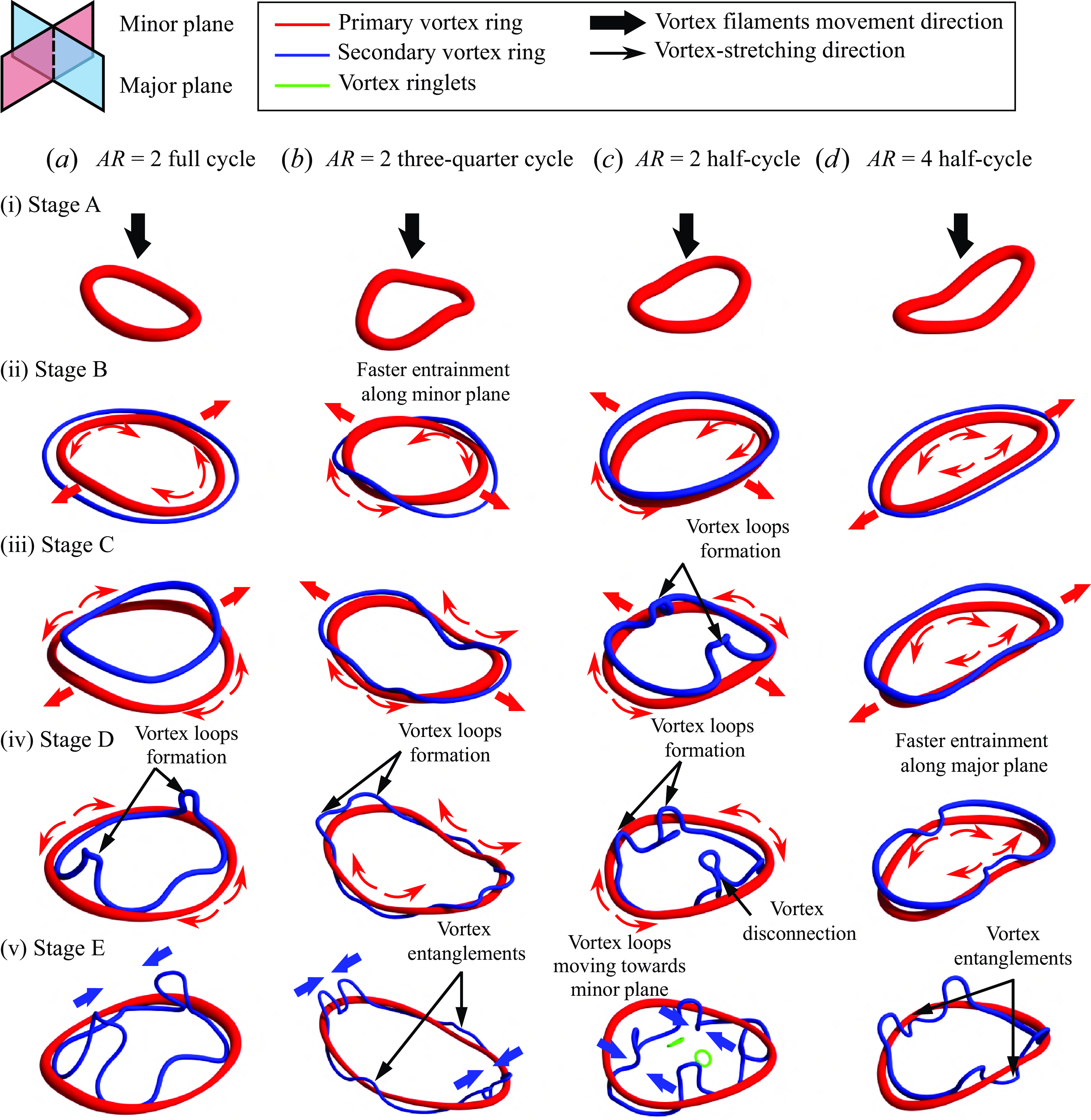
Figure 27. Three-dimensional vortex flow reconstructions for $AR=2$
EVR collisions with flatwall at (a) full-cycle, (b) three-quarter-cycle and (c) half-cycle locations, as well as for
$AR=2$
EVR collisions with flatwall at (a) full-cycle, (b) three-quarter-cycle and (c) half-cycle locations, as well as for $AR=4$
collision with flatwall at (d) half-cycle location.
$AR=4$
collision with flatwall at (d) half-cycle location.
Figure 27(a) shows the 3-D vortex flow reconstructions postulated for $AR=2$
EVR collision developments at full-cycle location, where EVR and SVR are coloured in red and blue, respectively. Thick arrows are used to indicate the vortex filament movements, while thin arrows highlight the vortex-stretching directions. The EVR axis-switching state at the point of collision is shown in stage A, where the EVR diameter is larger along the major plane, as shown in figures 3(a) and 4(b) previously. Additionally, vortex-ring segments along the minor plane are slightly ahead of those along the major plane. Despite this, SVR formation remains largely uniform along the EVR circumference in stage B. From the vortex-core trajectory result in figure 22(a)(i), vortex-ring segments along the minor plane will continue to move away from the collision axis, thereby increasing the EVR diameter there. Due to higher induced velocities in the vortex-ring segments along the major plane, stage C shows that SVR segments would leapfrog over and get entrained slightly faster by the EVR segments there. Hence, entrainment of SVR along both planes would differ as shown in stage D.
$AR=2$
EVR collision developments at full-cycle location, where EVR and SVR are coloured in red and blue, respectively. Thick arrows are used to indicate the vortex filament movements, while thin arrows highlight the vortex-stretching directions. The EVR axis-switching state at the point of collision is shown in stage A, where the EVR diameter is larger along the major plane, as shown in figures 3(a) and 4(b) previously. Additionally, vortex-ring segments along the minor plane are slightly ahead of those along the major plane. Despite this, SVR formation remains largely uniform along the EVR circumference in stage B. From the vortex-core trajectory result in figure 22(a)(i), vortex-ring segments along the minor plane will continue to move away from the collision axis, thereby increasing the EVR diameter there. Due to higher induced velocities in the vortex-ring segments along the major plane, stage C shows that SVR segments would leapfrog over and get entrained slightly faster by the EVR segments there. Hence, entrainment of SVR along both planes would differ as shown in stage D.
As the EVR diameter increases along the minor plane more than the major plane, its axes actually switch during the midst of the collision, which can be appreciated by the decreasing $\gamma$
in figure 25(a). Thus, induced velocities are now higher along the minor plane due to the smaller EVR segment radii, which in turn leads to increasingly larger influences over the SVR segments by the EVR segments along the minor plane than those along the major plane. These larger influences would cause vortex loops to form along the SVR segments more significantly along the minor plane, as depicted in stage D. As the axisswitching progresses with the EVR diameter becoming significantly larger along the minor plane than that along the major plane, higher levels of induced velocities would cause the vortex loops along the minor plane to move towards to the collision axis and away from the wall, as shown in stage E. In contrast, EVR segments along the major plane undergo the opposite flow processes and, as such, SVR vortex loops along the major plane would not exhibitthe behaviour described above for their minor plane counterparts. Instead, they would move towards the collision axis in a more muted fashion.
$\gamma$
in figure 25(a). Thus, induced velocities are now higher along the minor plane due to the smaller EVR segment radii, which in turn leads to increasingly larger influences over the SVR segments by the EVR segments along the minor plane than those along the major plane. These larger influences would cause vortex loops to form along the SVR segments more significantly along the minor plane, as depicted in stage D. As the axisswitching progresses with the EVR diameter becoming significantly larger along the minor plane than that along the major plane, higher levels of induced velocities would cause the vortex loops along the minor plane to move towards to the collision axis and away from the wall, as shown in stage E. In contrast, EVR segments along the major plane undergo the opposite flow processes and, as such, SVR vortex loops along the major plane would not exhibitthe behaviour described above for their minor plane counterparts. Instead, they would move towards the collision axis in a more muted fashion.
As for the collision at three-quarter-cycle location as depicted in figure 27(b), the EVR will be in a very different axis-switching state as compared with that at the full-cycle location. In this case, the EVR major and minor diameters are approximately equal at the point of collision, as shown in figures 3(a) and 4(b) earlier, although it is bending slightly towards the downstream direction along the minor plane, as depicted in stage A. Thus, EVR segments along the minor plane would encounter the wall to produce the SVR along that plane first. As the EVR flattens upon the wall, the formation of SVR would have propagated towards the major plane until it is fully formed, as depicted in stage B. This also leads to the earlier leapfrogging of SVR segments over the EVR along the minor plane. As the EVR stretches and increases in diameter along the major plane, as depicted in stage D, the entrained SVR segments begin to entangle around the EVR and towards the major plane. Concurrently, SVR segments would begin to leapfrog over the EVR along the major plane. Due to the increasingly smaller radii of curvature along this plane, said leapfrogged SVR segments would undergo rapid and more localised entrainment by the EVR, such that vortex loops would be formed along the same plane, as depicted in stage E. As the flow continues to develop, these vortex loops would move towards each other until flow incoherence increases and they transit to turbulence.
As the collision distance gets progressively shorter to half-cycle location as shown in figure 27(c), the fact that figure 3(a) shows that the EVR diameter is larger along the minor plane means that the EVR should take on the form presented in stage A. Note that EVR segments along the major plane are slightly ahead of their counterparts along the minor plane, as revealed by their vortex-core trajectories previously. As the EVR fully collides with the wall, as depicted in stage B, the SVR forms relatively uniformly around the flattened EVR before engaging in the leapfrogging process. This general uniformity can be attributed to the fact that, while the EVR segments along the major plane possess larger radii of curvature, they collide with the wall earlier and stretch away from the collision axis before their counterparts along the minor plane. This can be readily appreciated from their vortex-core trajectories presented in figure 22(iii) earlier. As such, this reduces curvature variations along the EVR and thus leads to a more uniform SVR formation. Since the EVR segments along the major plane continue to move away from the collision axis beyond those along the minor plane, this leads to increasingly higher localised induced velocities that see correspondingly more rapid localised leapfrogging at those locations. This produces the flow field shown in stage C, where vortex loops are formed from the SVR along the major plane.
Collating the flow visualisation and vortex-core trajectory results, it is postulated that these vortex loops move higher and towards the collision axis. Subsequently, the vortex loops elongate and take on an outline that resembles a hairpin vortex, which is similar to the secondary vortex loops in the study of Asselin & Williamson (Reference Asselin and Williamson2017) and Morris & Williamson (Reference Morris and Williamson2020). Similar to these studies,the vortex-stretching effect also draws the two ‘vortex legs’ of the secondary vortex loops towards each other and initiates pinch-off, which is essentially a vortex disconnection and reconnection process and results in the formation of vortex ringlets. The vortex ringlets then continue their journey towards the collision axis, as depicted in stage D. Meanwhile, as the SVR entangles around the EVR along the minor plane, two pairs of vortex loops are generated on both sides of the minor plane. They are postulated to move towards the minor plane in stage E and finally interact with each other based on the earlier flow visualisation in figure 14(i) and velocity vectors in figure 15(f).
Next, the 3-D vortex flow reconstructions for the $AR=4$
EVR colliding at half-cycle location are shown in figure 27(d). At this location, its axis-switching state will be similar to that depicted in figure 27(c) for its
$AR=4$
EVR colliding at half-cycle location are shown in figure 27(d). At this location, its axis-switching state will be similar to that depicted in figure 27(c) for its $AR=2$
counterpart. Unsurprisingly, the collision behaviour will be quite similar as well, with stage A showing the SVR forming more or less uniformly around the
$AR=2$
counterpart. Unsurprisingly, the collision behaviour will be quite similar as well, with stage A showing the SVR forming more or less uniformly around the $AR=4$
EVR. While the SVR will begin leapfrogging over the EVR as shown in stage B, it will not incur the vortex loops as seen for the
$AR=4$
EVR. While the SVR will begin leapfrogging over the EVR as shown in stage B, it will not incur the vortex loops as seen for the $AR=2$
EVR by stage C. This is because the EVR segments along the major plane do not move as fast nor as much as those observed for the
$AR=2$
EVR by stage C. This is because the EVR segments along the major plane do not move as fast nor as much as those observed for the $AR=2$
EVR by stage C. Instead, the SVR segments along the major plane will be entrained by and entangle around the EVR by stage D, before propagating along the EVR towards the minor plane. Based on the earlier flow visualisation in figure 19(h), it is postulated that new vortex loops are formed adjacent to the major plane during the entanglements, giving rise to the situation depicted in stage E. The vortex loop pairs would move inwards and towards the minor plane like what happens in stage E in figure 27(c), before they interact with each other after the EVR transits to incoherent.
$AR=2$
EVR by stage C. Instead, the SVR segments along the major plane will be entrained by and entangle around the EVR by stage D, before propagating along the EVR towards the minor plane. Based on the earlier flow visualisation in figure 19(h), it is postulated that new vortex loops are formed adjacent to the major plane during the entanglements, giving rise to the situation depicted in stage E. The vortex loop pairs would move inwards and towards the minor plane like what happens in stage E in figure 27(c), before they interact with each other after the EVR transits to incoherent.
4. Conclusions
Collisions between $Re=4000$
,
$Re=4000$
, $AR=2$
and 4 EVRs and a wall have been studied using PLIF visualisations and TR-PIV measurements. The collision locations are based on the key axis-switching stages of each EVR to better appreciate effects of axisswitching on the collision outcomes. Four and two distinct axis-switching locations have been identified from freely translating
$AR=2$
and 4 EVRs and a wall have been studied using PLIF visualisations and TR-PIV measurements. The collision locations are based on the key axis-switching stages of each EVR to better appreciate effects of axisswitching on the collision outcomes. Four and two distinct axis-switching locations have been identified from freely translating $AR=2$
and 4 EVRs, respectively. The four locations for
$AR=2$
and 4 EVRs, respectively. The four locations for $AR=2$
EVR cover one complete axis-switching cycle and comprise of the quarter-, half-, three-quarter and full-cycle locations. Due to bifurcations in the
$AR=2$
EVR cover one complete axis-switching cycle and comprise of the quarter-, half-, three-quarter and full-cycle locations. Due to bifurcations in the $AR=4$
EVR, only the quarter- and half-cycle locations are studied. Results show that the collision outcomes are highly sensitive to the exact axis-switching location, due to the different EVR states that give rise to different induced velocity distributions just prior to the collisions. This proves that the selection of the orifice-to-wall distance is not a trivial matter for non-circular vortex-ring collisions. For
$AR=4$
EVR, only the quarter- and half-cycle locations are studied. Results show that the collision outcomes are highly sensitive to the exact axis-switching location, due to the different EVR states that give rise to different induced velocity distributions just prior to the collisions. This proves that the selection of the orifice-to-wall distance is not a trivial matter for non-circular vortex-ring collisions. For $AR=2$
EVR collisions at different locations, major and minor planes produce different vortex-stretching or compression behaviours due to circumferential flows moving from one plane to another. Non-uniform formation and entrainment of SVR result in different SVC behaviours, such as SVCs colliding at the full-cycle location and small-scale vortexdipoles forming from SVR at the half-cycle location. As for
$AR=2$
EVR collisions at different locations, major and minor planes produce different vortex-stretching or compression behaviours due to circumferential flows moving from one plane to another. Non-uniform formation and entrainment of SVR result in different SVC behaviours, such as SVCs colliding at the full-cycle location and small-scale vortexdipoles forming from SVR at the half-cycle location. As for $AR=4$
EVR, the flow behaviour at the half-cycle location clearly demonstrates the effects of doubling the aspect ratio. Interestingly, however, it does share similar flow outcomes with the
$AR=4$
EVR, the flow behaviour at the half-cycle location clearly demonstrates the effects of doubling the aspect ratio. Interestingly, however, it does share similar flow outcomes with the $AR=2$
EVR at the quarter-cycle location, implying that confinement effects could dominate over the EVR vortex dynamics when the orifice-to-wall distance is very small.
$AR=2$
EVR at the quarter-cycle location, implying that confinement effects could dominate over the EVR vortex dynamics when the orifice-to-wall distance is very small.
Vortex-core trajectory results depict very different outcomes along major and minor planes as the collision location varies, where the resulting vortex-core movements are dependent on the relative dominance between the inherent expansion of the EVR diameter due to the collision and motions of the EVR segments along the major/minor plane under the influences of induced velocities due to axisswitching. Circulation results reveal that, in general, small to moderate but momentary increments in the circulation levels tend to occur for $AR=2$
EVR collisions, although they fall below those of their freely translating counterparts very quickly after that. Compared with CVR collisions, circulation reductions for EVR collisions are more significant. As for
$AR=2$
EVR collisions, although they fall below those of their freely translating counterparts very quickly after that. Compared with CVR collisions, circulation reductions for EVR collisions are more significant. As for $AR=4$
EVR, however, circulation increments during the collision are not that apparent. As such, the results suggest that the circulation behaviour will differ even greater when the vortex-ring geometry deviates further away from a circular one.
$AR=4$
EVR, however, circulation increments during the collision are not that apparent. As such, the results suggest that the circulation behaviour will differ even greater when the vortex-ring geometry deviates further away from a circular one.
Lastly, 3-D vortex flow reconstructions for all collision scenarios for both EVRs are provided. The formation and early entrainment of SVR at full- and half-cycle locations of $AR=2$
EVRs are largely uniform. However, different vortex-stretching states along the EVR circumference contribute to subsequent non-uniform entrainment of SVR and formation of vortex loops. In particular, it is postulated that a pair of vortex loops along the minor plane stretches and moves towards the collision axis at full-cycle location. Additionally, non-uniform entrainment of the SVR at the half-cycle location not only gives rise to vortex loops but also vortex ringlets due to vortex disconnection and reconnection. In contrast, the formation and entrainment of SVR at three-quarter-cycle location are non-uniform from the beginning. As a result, intense vortexstretching along the minor plane leads to SVR filaments entangling around the EVR. Finally, the 3-D vortex flow reconstruction for
$AR=2$
EVRs are largely uniform. However, different vortex-stretching states along the EVR circumference contribute to subsequent non-uniform entrainment of SVR and formation of vortex loops. In particular, it is postulated that a pair of vortex loops along the minor plane stretches and moves towards the collision axis at full-cycle location. Additionally, non-uniform entrainment of the SVR at the half-cycle location not only gives rise to vortex loops but also vortex ringlets due to vortex disconnection and reconnection. In contrast, the formation and entrainment of SVR at three-quarter-cycle location are non-uniform from the beginning. As a result, intense vortexstretching along the minor plane leads to SVR filaments entangling around the EVR. Finally, the 3-D vortex flow reconstruction for $AR=4$
EVR at the half-cycle location is also generally similar to its
$AR=4$
EVR at the half-cycle location is also generally similar to its $AR=2$
counterpart. With the flow mechanisms of EVR–wall collisions clarified in this study, more applied aspects of the present collision scenarios will be considered in the future, such as how they could possibly improve upon heat transfer and other flow characteristics.
$AR=2$
counterpart. With the flow mechanisms of EVR–wall collisions clarified in this study, more applied aspects of the present collision scenarios will be considered in the future, such as how they could possibly improve upon heat transfer and other flow characteristics.
Supplementary movies.
Supplementary movies are available at https://doi.org/10.1017/jfm.2025.401.
Acknowledgements.
The authors gratefully acknowledge support for the present study by the School of Mechanical and Aerospace Engineering, Nanyang Technological University.
Funding.
This research received no specific grant from any funding agency, commercial or not-for-profit sectors.
Declaration of interests.
The authors report no conflict of interest.
Data availability statement.
The data that support the findings of this study are available from the corresponding author upon reasonable request.


 Open access