


1. Introduction
By analyzing samples from glaciers and ice sheets, it is possible to gain a detailed understanding of paleoclimate events (Barbante and others, 2013), identify and date natural catastrophes such as volcanic eruptions and forest fires over timescales ranging from decades to hundreds of millennia, and study the dynamics and physical properties of natural ice, along with other potential research targets in Polar Regions.
In Greenland, the first identification of tephra in ice cores revealed a connection between the layer and the 1982 AD eruption of Mount El Chichón. Later, studies of the GISP, GRIP, GISP2 and NGRIP ice cores uncovered several previously undiscovered eruptions (Abbott and Davies, Reference Abbott and Davies2012).
Tephra layers are typically of high scientific value (Plunkett and others, Reference Plunkett2020) but are present in limited quantities. For instance, while 800 volcanic events were identified from the GISP2 ice cores, tephra layers were found in only 45 of them (Abbott and Davies, Reference Abbott and Davies2012). Therefore, to obtain a sufficient quantity of specific layers, including tephra, shearing zones and basal ice (Talalay and Hong, Reference Talalay and Hong2020), a replicate coring method is necessary to supplement conventional vertical coring with additional samples.
Although long-term observation of boreholes can provide valuable scientific data (Zagorodnov and others, Reference Zagorodnov2012), as demonstrated in Vostok Station for replicate coring (Turkeev and others, 2021), nearly all conventional methods cause damage to the lower section of the parent borehole, making it impossible to conduct long-term observations (Talalay and Hong, Reference Talalay and Hong2020). An exception is the Deep Ice Sheet Coring (DISC) replicate coring tool, which prevents damage to the lower wall by creating a deviation at the upper section at a different azimuth (Gibson and others, Reference Gibson, Johnson, Shturmakov, Mortensen and Goetz2014). However, the mechanical structure of the DISC tool is complex and expensive, and it can only be used in boreholes with diameters >170 mm, while most polar ice boreholes are <135 mm. Furthermore, the deviation angles of existing methods for obtaining additional core samples after the borehole has been drilled are highly restricted, limiting the amount of ice sample that can be collected.
Compared to deviation coring, sidewall coring can provide far more replicate ice core samples while causing minimal damage to the parent borehole wall. Currently, sidewall coring is widely used in conventional rock drilling. However, existing sidewall coring tools cannot be directly applied in polar ice coring, as most ice boreholes have smaller diameters, suffer from refreezing issues and are more sensitive to contamination, especially when using percussion corers that employ explosive powder. Additionally, the mechanical structure of sidewall coring tools used in oil and exploration drilling is complex, making operation and maintenance challenging. The high strength of rock walls necessitates the use of horizontal core barrels and straight coring tracks, which require high power. Typically, conventional mechanical sidewall coring tools penetrate the wall to a depth less than the inner diameter of the tool, resulting in a short single coring length for each run (<64 mm) (Varhaug and Smithson, Reference Varhaug and Smithson2015). Ice, being a unique type of rock with a low melting point, allows for the easy application of thermal coring methods.
The Thermal Sidewall Ice Corer (TSIC) for sampling horizontal ice sheet layers has been proposed and tested at the Institute for Polar Science and Engineering, Jilin University. The TSIC is capable of creating a sidewall hole with a diameter of <60 mm at any azimuth of the parent borehole and retrieving ice cores with a diameter >20 mm and a total length of approximately 500 mm. A camera is integrated into the TSIC to precisely locate the corer at the targeted depth.

Figure 1. General structure of the Thermal Sidewall Ice Corer: sectional view showing both the outer shell and inner components. The featured bending coring structure is installed inside the corer and extends through a hole in the outer shell for drilling.
2. Corer structure
2.1. General concept
The TSIC consists of a thermal coring head, bending core barrel, screw pairs, driven unit, guiding pipe, top and bottom anti-torque structures, and pressure chamber (Fig. 1). The diameter of most ice boreholes is typically <135 mm. To accommodate the auxiliary mechanisms and provide tolerance, the outer diameter of the corer is designed to be 130 mm, ensuring compatibility with the diameter of ice boreholes. Simultaneously, adhering to the principle of minimizing the size of the drill, the total length is designed to be ∼2.3 m. Descriptions of the subsystems are provided in the following sections.
2.2. Driven unit and screw pairs
The screw pair driven by an electric motor is used to drive the core barrel, apply drill load to the core barrel and transfer it to the thermal coring head to penetrate the ice. The screw pairs are located at the upper part of the drill, between the motor and the bending core barrel, and consist of an internal screw and an external screw. The internal screw is connected to the shaft of the motor located in the motor chamber. As the internal screw rotates with the motor, the external screw, to which the bending core barrel is attached at its lower end, is driven. By controlling the forward rotation of the motor, the screw pairs move the upper end of the bending core barrel downward. Both the internal screw and the external screw are designed to be 0.5 m in length.
2.3. Bending core barrel and guiding structure
A bending core barrel (Fig. 2) is proposed to effectively utilize the inner space of the drill by converting the vertical movement of the coring tool into horizontal motion. The outer diameter (40 mm) of the bending core barrel is slightly smaller than that of the thermal coring head. The inner diameter is designed to be 30 mm, and the total length of the barrel is 460 mm, with each unit having a length of 20 mm. Eight holes are positioned along the pipe wall to allow the passage of electric wires for heating elements. The bending core barrel consists of 23 identical units connected by pins. Each unit is cylindrical in shape, and the pins are arranged radially along the horizontal plane of all the cylinders. Each unit rotates around the center of the pin, and the entire bending core barrel bends only along its vertical symmetric plane.
Figure 2. Structure and posture of the bending core barrel. Two different postures show how the core barrel can bend under a multi-joint structure. An enlarged view of a single unit of the core barrel also illustrates how wires from the drill head can pass through holes in it.
After being pushed by the external screw from the top end, the bending core barrel moves through the inner bent tunnel of the guiding structure, with its direction of motion diverted to horizontal. The drilling direction is strictly confined to the inner tunnel of the guiding structure, which includes a 90∘ arc pipe (Fig. 3). Once the installation is complete, the guiding structure is seated on the support shelf and suspended in the drill. Throughout the process, the thermal coring head is pushed by the bottom end of the bending core barrel toward the ice wall. It is assumed that the moving tolerance of the core barrel is  $ \lt \pm$1∘.
Figure 3. Guiding structure for stable movement of the coring tool. The coring head and core barrel can extend through the guiding structure, which is an approximately L-shaped curved circular tube, to drill into the borehole wall. A camera is also installed above the outlet of the guiding structure to more precisely locate the targeted depth.
2.4. Thermal coring head
Thermal electric drills typically feature simple structures and are suitable for multiple types of ice layers, including temperate glaciers (Zagorodnov and Thompson, Reference Zagorodnov and Thompson2014). To simplify the design of the sidewall coring tool, a thermal coring head is installed at the end of the coring barrel instead of a traditional mechanical drill head (Fig. 4). Once the thermal coring head makes contact with the ice wall, the driven unit and screw pairs provide drill load through the bending core barrel to the thermal coring head. By adjusting the input power to the motor, the thermal coring head can operate under varying weight on bit (WOB), achieving a coring length of 0.5 m.
Figure 4. Thermal coring head installed at the front of two connected units of the bending core barrel. Heating elements are inside the coring head. Electric wires can pass through the units of the core barrel and are protected from damage.
After the coring tool has drilled into the ice sheet, forming both a sidewall hole and an ice core, the coring tool is withdrawn. The core catcher first cuts the complete ice core during this process. As the bending core barrel moves through the guiding structure, the ice core is broken into smaller pieces by the shearing force from the inner surface of the core barrel and stored in the main body of the TSIC. The ice sample is then brought to the surface along with the corer.
2.5. Anti-torque systems
Anti-torque systems are installed at both the top and bottom of the TSIC for two main purposes. First, they serve as centralizers, ensuring the corer remains centered in the borehole. Second, these systems prevent the body of the corer from spinning under the torque exerted by the stator of the driving motor. Additionally, the anti-torque systems allow the corer to move up and down during tripping operations. The upper anti-torque system consists of four identical small wheel structures, each with a rod connecting the center of the wheel to the upper cover of the corer body. The rods are fixed by screws to maintain appropriate clearance between the borehole wall and the anti-torque wheel surface, thereby generating the required anti-torque force. The bottom anti-torque structure is composed of four prebent leaf springs, each supported by hinges at their ends and mounted along the corer extensions. In addition to the upper motor in the driven unit, an extra motor can be mounted on top of the bottom anti-torque structure to connect it to the main corer body, enabling relative rotation between the two parts (the extra motor is not shown in Fig. 1). The coring azimuth can be adjusted by independently controlling the extra motor.
3. Coring head individual tests
3.1. Thermal coring head pretests
To obtain a sufficient volume of ice samples, the designed outer diameter of the coring head is 40 mm, and the inner diameter is 30 mm. The total length of the entire coring tool, including the coring head and the bending core barrel, exceeds 500 mm, and the targeted rate of penetration (ROP) under rated voltage is set to 2 m h−1. Given the relatively small size of the thermal coring head, it was initially decided to test whether this tiny-sized thermal coring method is feasible, following the basic practical experience of conventional thermal coring methods. Additionally, these pretests would provide valuable insights for subsequent optimal design. Thermal coring pretests were, therefore, conducted to evaluate the real working ROP under different input power and WOB conditions. For the preliminary tests, ice blocks with a temperature of −30∘C were prepared. According to Talalay and others Reference Talalay, Zagorodnov, Markov, Sysoev and Hong(2014), under ice temperatures of −10∘C, −20∘C and −30∘C, with a designed input power of 240 W, the expected ROPs would be 3.1 m h−1, 2.9 m h−1 and 2.8 m h−1, respectively. The ROP obtained from experimental data was then compared with the theoretical calculations.
All tests were completed in the National Complex Drilling Technology Laboratory at the Chaoyang campus of Jilin University. The body of the coring head was made from copper (Fig. 5). Eight heating cartridges, each with a power of 30 W, were inserted into holes in the coring head. Thermal adhesive was used for preliminary waterproof treatment at the connections between the cartridges and lead wires. The thermal coring head was connected to a non-bendable drill pipe, and the end of the drill pipe was attached to the winch cable of the test stand. The voltage for the thermal head was supplied through a single-phase transformer, which could be adjusted, and the input wire was connected to an ammeter and voltmeter to measure the actual voltage and current. All data were collected by the control system.
Figure 5. Drill head connected with drill pipe for vertical coring pretest. A temporary drill stem is connected to the bottom of the drill head to provide tripping movement and transfer drill load to it. Ice samples are produced by a box-shaped module. Waterproof glue is used for insulation at the end of the heating elements.
Before the start of the test, after the drill was fully suspended, the control system was used to set the initial weight of the corer prototype. The ice sample was placed under the coring head, and the winch of the test stand was used to lower the coring head onto the surface of the ice sample. The transformer voltage was adjusted to zero for safety protection.
The tests consisted of two parts: tests under different power levels and tests under different WOB conditions. In the tests under varying power, the control system was used to maintain a constant WOB for each group. It was considered that there is an optimal maximum effective bottom surface pressure for improving the ROP. According to related papers, this value is 1.5 kPa for the RECAS thermal sonde with a diameter of 160 mm (Talalay and others, Reference Talalay, Li, Sysoev, Hong, Li and Fan2019) and 8.2 kPa for another hot point with a diameter of 55 mm (Li and others, Reference Li, Talalay, Sysoev, Zagorodnov, Li and Fan2020). It can be observed that the highest effective pressure on the drill head increases rapidly as the drill head working area becomes smaller. Since the diameter of the designed coring head is 40 mm—much smaller than the abovementioned drill heads—and the coring head is hollow with a relatively small working area (5.5 cm2), a pressure of 18.2 kPa, which is more than double the 8.2 kPa, was chosen as the optimal pressure for the drill head. This pressure corresponds to the maximal effective WOB of 10 N. The transformer was used to adjust the input voltage to the thermal coring head, thereby varying the input power. A total of five tests were conducted in this part, with input powers of 50 W, 100 W, 150 W, 200 W and 250 W (Table 1).
Table 1. Coring data from pretests of the prototype in the lab
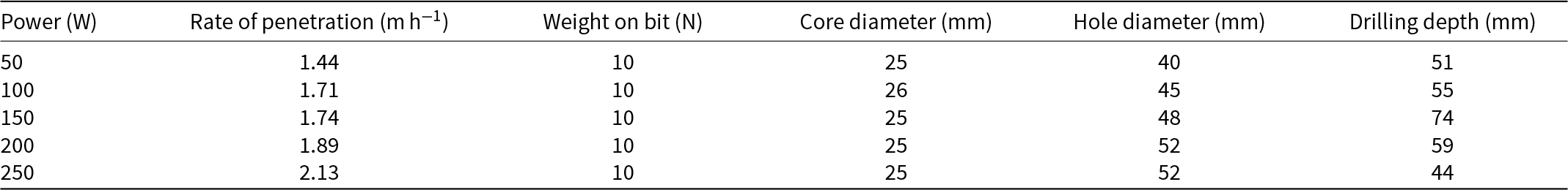
In the tests under varying WOB, the transformer was used to maintain a constant input power of 240 W for the coring head, which corresponds to the rated full power under a voltage of 220 V. Four tests were conducted with WOB values of 10 N, 15 N, 20 N and 25 N for the coring head. All tests were performed at an ice temperature of −30∘C (Fig. 6). After completing all tests, the core diameter and hole diameter were measured at several sections, and averages were calculated. According to the results, the ROP under the highest power was lower than the theoretical estimation when the WOB was maintained at 10 N. However, the ROP closely matched the estimated 2.8 m h−1 when the WOB reached 25 N, indicating that 25 N is closer to the highest effective pressure for the coring head. When the WOB was below 25 N, increasing the WOB under rated voltage resulted in a higher ROP.
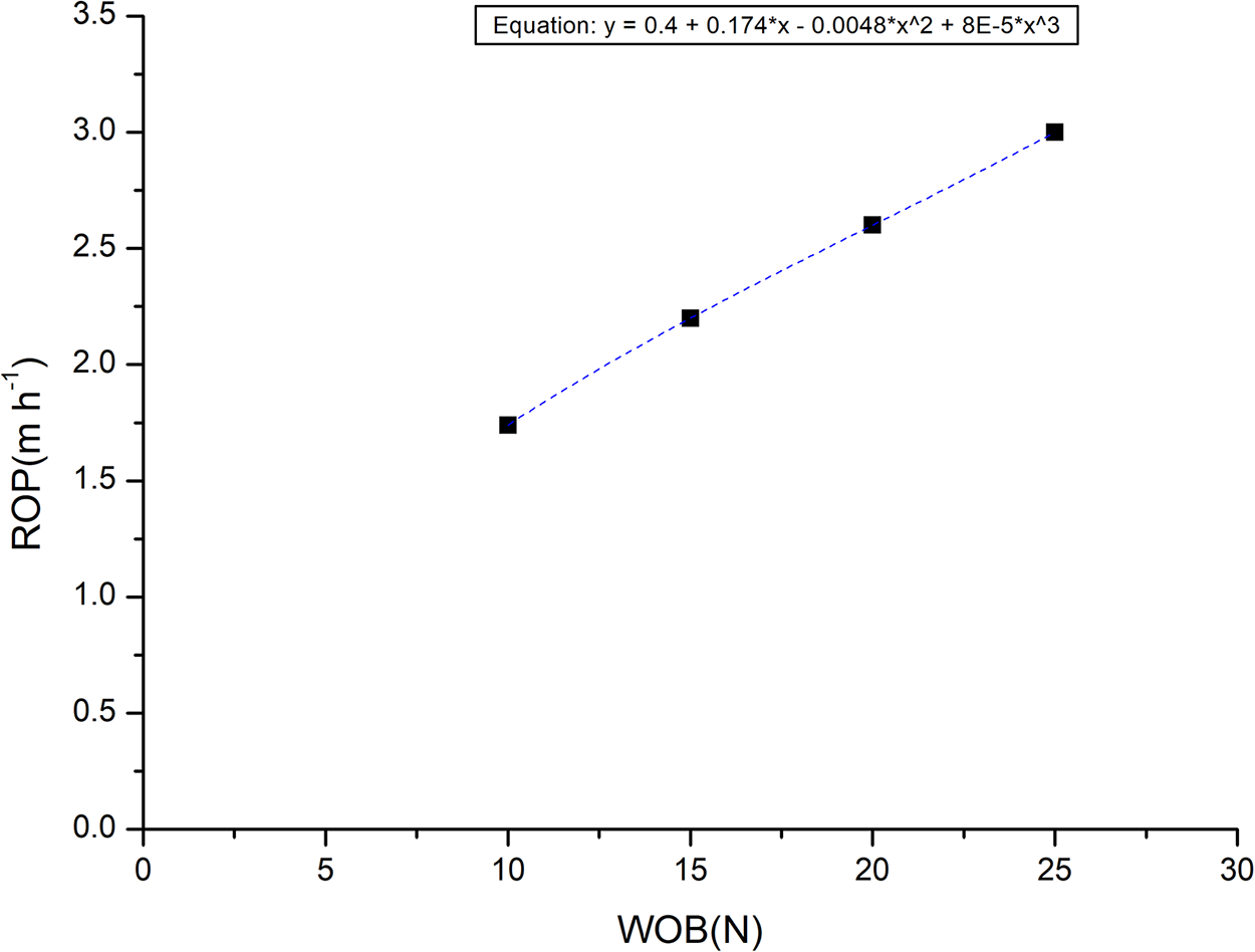
Figure 6. Rate of penetration change under weight on bit of 10 N, 15 N, 20 N and 25 N. The ice temperature is −30∘C. The Gaussian fitting method is adopted to draw a fitting curve for the data.
Ice cores with a nearly cylindrical shape were recovered (Fig. 7). Due to the continuous heating by meltwater, most of the cores exhibited a conical tip at the top. The diameter of the ice cores ranged from 25 mm to 27 mm, while the diameter of the borehole ranged from 40 mm to 52 mm.
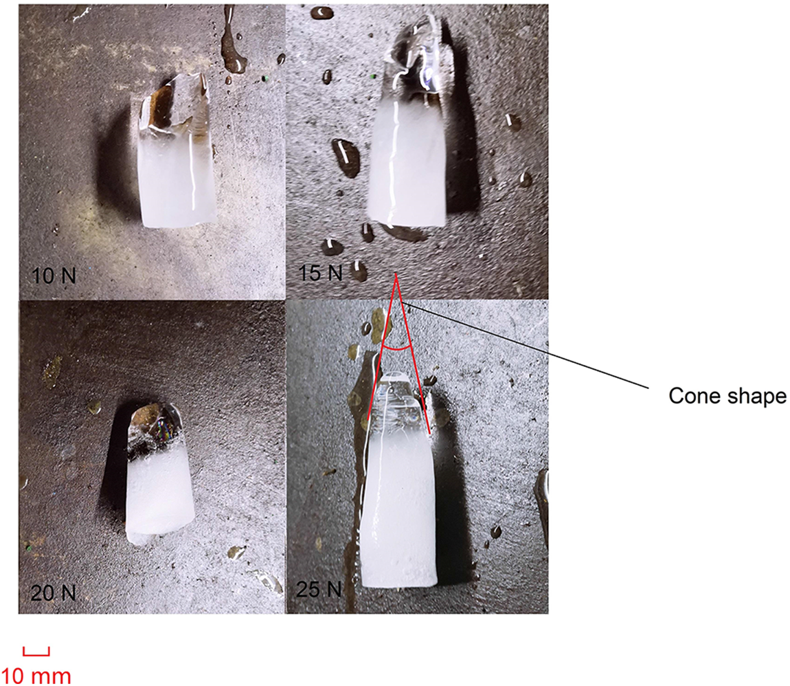
Figure 7. Retrieved ice cores under different weight on bit during pretests. The diameter of the ice cores are 25–27 mm. The shape of ice core is generally cylindrical, but replicate heating by meltwater is assumed to form the cone-shaped tip on bottom of each ice core.
3.2. Improvement of thermal head
Based on the thermal coring pretests, the small-sized coring method was evaluated as feasible, and the acceptable coring quality was confirmed. However, to improve the efficiency of coring, it was decided to replace the cartridge heaters with a tubular lateral heater. Numerical simulations also demonstrated that the thermal distribution on the surface of the tubular lateral heater coring head is more even than that of the cartridge heater (Fig. 8). Additionally, to save more space for installation along the radial direction of the coring head, the outer diameter of the coring head was increased to 56 mm, and the input power was raised to 560 W to achieve a maximum penetration rate of approximately 2 m h−1.

Figure 8. Modeled surface thermal distribution of (a) cartridge heater coring head and (b) tubular lateral heater coring head. There is no significant difference in the absolute value between both designs, but the tubular lateral heater provides a more even thermal field, improving drilling performance.
4. Sidewall coring tests
4.1. Test stand
In the thermal sidewall coring test stand (Fig. 9), the corer was simplified by eliminating the outer shell for easier monitoring and mechanical debugging. The integrated test stand includes a motor, screw pairs, guiding structure, bending core barrel, thermal coring head, ice sample board on sliding rails and an electric control module (transformer and motor controller) (Fig. 10).

Figure 9. Sidewall thermal coring test stand without outer shell for convenient monitoring and mechanical debugging. Both the guiding structure and the motor are fixed on mast of the metal frame. A movable board could carry ice samples and slide on rails to provide operation space before and after tests.

Figure 10. Electric control module including transformer and motor controller. Multimeter and ammeter are connected to the circuit loop during test to monitor and measure input voltage and current.
4.2. Sidewall coring test performance
Seven groups of tests were conducted under different input power levels. A parallelepiped block of artificial ice with a temperature of −15∘C was used to imitate a natural ice massif. For each group of tests, photos were taken to analyze the shape of each ice core and the sidewall borehole. After completing each group of tests, the drilling depth and drilling time were recorded to calculate the ROP. The core diameters at both ends of each ice core were measured and designated as core diameter 1 and core diameter 2, respectively (Table 2).
Table 2. Performance and results in sidewall coring tests
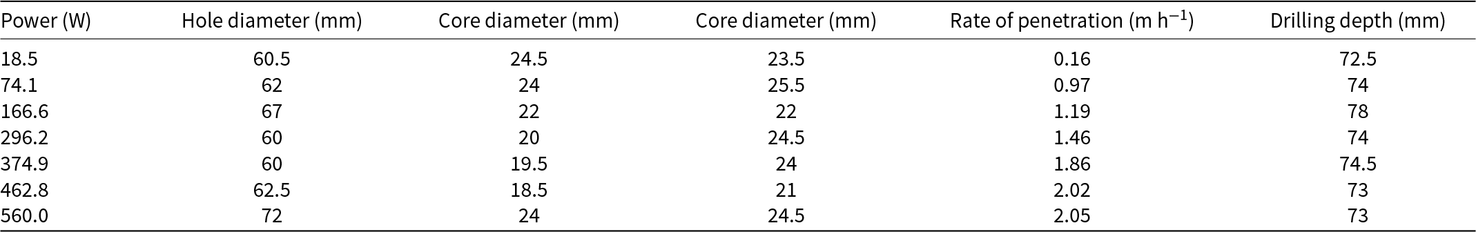
For each combination of drilling parameters, it was observed that the ROP steadily increased from 0.3 to 2.1 m h−1 as the input power increased from 20 W to the full 560 W (Fig. 11). The tested ROPs were consistently higher than the theoretical results (except for at the highest input power) because the meltwater drained from the borehole, preventing repeated heating of the meltwater. However, at the full power of 560 W, the test result was lower than the theoretical estimation, which is assumed to be due to the vaporization of water at high heating temperatures.
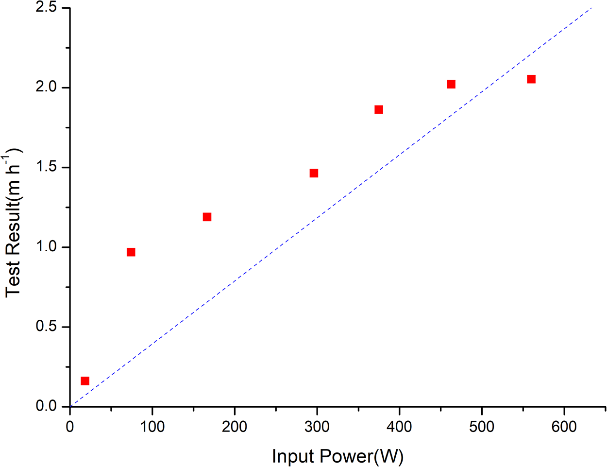
Figure 11. Rate of penetration–power relation (test results as dots and theoretical estimations as a line). The ice temperature is −15∘C. Rate of penetration is calculated by drilling time and drilling depth.
The diameter of the retrieved ice cores, calculated as the average of core diameter 1 and core diameter 2, ranged from 19 mm to 26 mm (Fig. 12). The meltwater produced during the drilling process was fully drained along the borehole wall, having minimal impact on the ice core quality (Fig. 13). During drilling, a shallow groove formed on the bottom side of the borehole (Fig. 13).
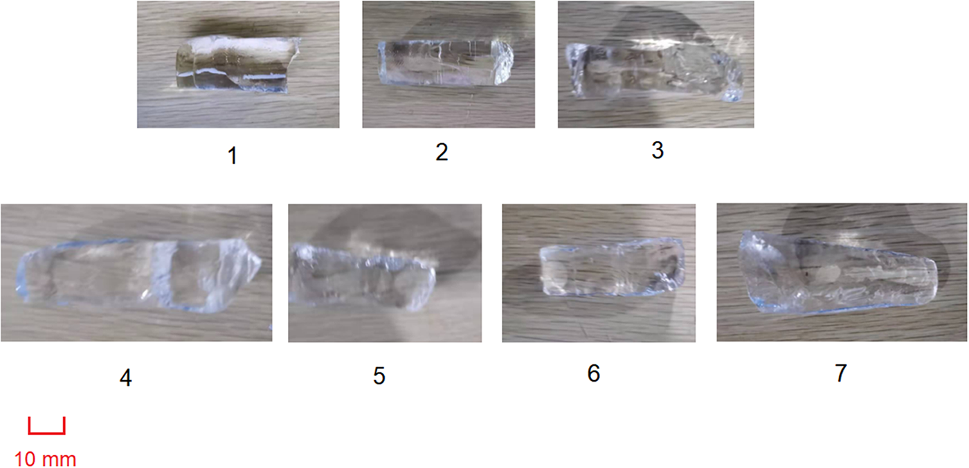
Figure 12. Ice cores retrieved dryly with non or slight cone-shaped tip. All cores are successfully broken by the tiny core catcher behind drill head and are rarely melted by the meltwater.
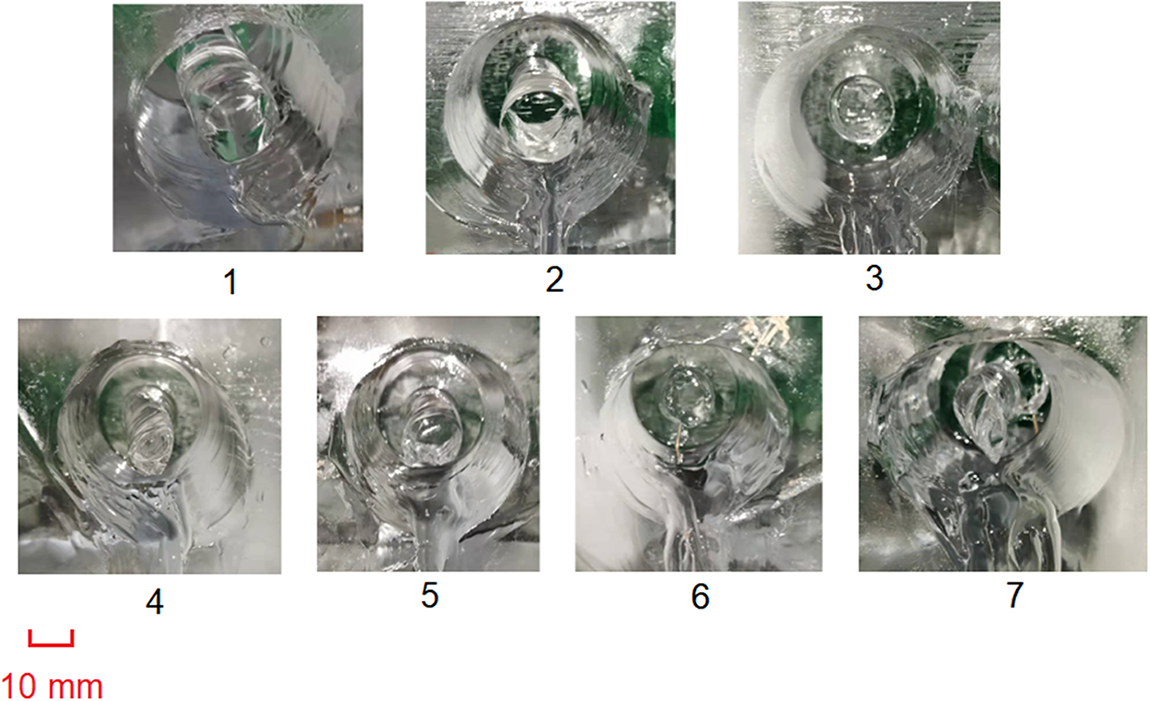
Figure 13. Sidewall borehole shape showing the influence of sidewall hole meltwater. A clear groove is left on downside of each sidewall hole. No meltwater remains inside of the holes, and the most of the hole wall is well preserved.
5. Discussion
The newly proposed TSIC system is the first coring tool designed to drill into the sidewall of an existing ice borehole. The TSIC is capable of retrieving ice samples with a diameter of 19–26 mm and a length of 0.5 m. Additionally, the produced sidewall hole, with a diameter of ∼50 mm, can accommodate the installation of various sensors for long-term observation within the borehole. During laboratory tests, the TSIC achieved a maximum ROP of over 2 m h−1, which aligns well with theoretical estimates. It has been confirmed that the meltwater produced during the drilling of the sidewall hole does not affect the ice core quality, as it drains out of the hole.
In the coring head individual tests, the highest effective pressure for the WOB was assumed to be 20 kPa. However, it was found that the ROP continued to increase even after the pressure exceeded 20 kPa. This suggests that the highest effective pressure for the small coring head developed could be higher than 20 kPa. Although an ROP of around 3 m h−1 is sufficient for sampling tasks, further testing and discussion are needed to determine the final highest effective pressure for the WOB. Additionally, a WOB pressure of more than 20 kPa was shown to be sufficient to maximize ROP in the sidewall coring tests. The observed difference is likely due to the phase change, which removed excessive heat during the vaporization of water.
For future optimization, as TSIC is the first thermal sidewall coring tool, it is currently capable of operating only in dry boreholes. Therefore, after the conditions for dry sidewall coring are thoroughly studied, further waterproof design improvements will be incorporated to extend its coring capabilities to holes with drilling fluid. Another significant challenge will be preventing the drill parts from refreezing due to the meltwater present in the drilling fluid.
Acknowledgements
This work was supported by the National Key Research and Development Project of the Ministry of Science and Technology of China (Grants No. 2023YFC2812602 and 2021YFC2801401) and the National Natural Science Foundation of China (Grant No. 41941005).


 Open access