


1 Introduction
High-power fiber lasers have become indispensable tools for applications ranging from scientific research to industrial processing, due to their superior beam quality and power scalability. Among the key limitations to further power scaling, transverse mode instability (TMI) emerges as the most critical barrier for near-diffraction-limited fiber lasers[ Reference Jauregui, Stihler and Limpert 1 – Reference Palma-Vega, Jáuregui, Hässner, Möller, Kuhn, Nold, Tünnermann, Limpert, Haarlammert and Schreiber 3 ]. The prevailing understanding attributes TMI to thermally induced refractive index gratings (RIGs) formed by the modal interference pattern (MIP) between the fundamental mode (FM) and the high-order mode (HOM), with a critical phase shift enabling energy transfer[ Reference Jauregui, Eidam, Limpert and Tünnermann 4 – Reference Smith and Smith 8 ]. Current mitigation strategies primarily target mode control via fiber coiling, a reduced numerical aperture (NA), etc., to suppress HOMs[ Reference Beier, Möller, Sattler, Nold, Liem, Hupel, Kuhn, Hein, Haarlammert, Schreiber, Eberhardt and Tünnermann 9 , Reference Zeng, Wang, Yang, Zhang and Xu 10 ], and thermal management through fiber core diameter optimization and pump wavelength tuning to mitigate the generation of RIGs[ Reference Li, Wu, Li, Huang, Xiao, Yang, Yan, Pan and Zhou 11 ].
High-power supercontinuum sources are essentially broadband fiber lasers, with advantages including broad spectrum, excellent directionality and high brightness, and have emerged as promising tools for diverse applications including remote environmental sensing and hyperspectral imaging[ Reference Kääriäinen and Dönsberg 12 – Reference Brown, Liu and Philbrick 15 ]. Fiber amplifier structures are widely adopted in high-power supercontinuum generation due to their capability to simultaneously deliver pulsed lasers with high output power and near-diffraction-limited beam quality[ Reference Jiang, Song and Hou 16 – Reference Shen, Fang, Zhao, Ouyang, Wang, Wu and Ruan 21 ]. In 2021, a 314 W supercontinuum spanning 390–2400 nm was generated using a gradually tapered photonic crystal fiber pumped by a master-oscillator-power-amplifier system[ Reference Zhang, Li, Liao, Dong, Li, Lin, Wang and Jing 17 ]. By 2023, an ytterbium-doped fiber amplifier achieved 714 W supercontinuum output[ Reference Jiang, Song, He and Hou 19 ]. The highest reported power of a supercontinuum exceeds 3 kW[ Reference Qi, Yang, Li, Yan, Gong and Xiao 22 ], generated by an open-cavity random Raman fiber laser using a 46/400 μm passive fiber. While using large-core fibers may degrade beam quality due to higher-order modes, the mode property of the output laser was not explicitly characterized in Ref. [Reference Zhan, Fu, Zhang, Duan, Zhang, An, Liu and Jiang23]. All the aforementioned supercontinuum sources have randomly polarized emission. However, linearly polarized supercontinuum sources have shown application value in active hyperspectral imaging and material characterization[ Reference Zhan, Fu, Zhang, Duan, Zhang, An, Liu and Jiang 23 ]. Scaling the power of linearly polarized supercontinuum sources is challenging because the concentrated energy in a single polarization state lowers the threshold of nonlinear effects and the borosilicate stress rods in polarization-maintaining (PM) fibers have lower thermal and chemical stability compared to silica, which reduces the power-handling capabilities of PM fibers compared to non-PM fibers[ Reference Zhou, Huang, Xu, Ma, Su, Wu and Liu 24 ]. To date, the highest output power of a linearly polarized supercontinuum is 322.4 W[ Reference Li, Zhao, Li and Chen 25 ], generated from a PM amplifier.
While TMI has been widely studied in conventional fiber lasers[ Reference Palma-Vega, Jáuregui, Hässner, Möller, Kuhn, Nold, Tünnermann, Limpert, Haarlammert and Schreiber 3 , Reference Tao, Xiao, Zhang, Leng, Wang, Zhou and Xu 26 – Reference Wu, Li, An, Li, Chen, Xiao, Huang, Yang, Yan, Leng, Pan and Zhou 30 ], it has not been reported in supercontinuum generation. This may be primarily due to the average power of a supercontinuum usually being below the TMI thresholds, and the dramatic spectral broadening during supercontinuum generation significantly reduces modal field overlap across different wavelength components, thereby weakening the formation of the MIP. However, as supercontinuum sources progress toward higher average power, TMI may emerge as a new limiting factor, necessitating systematic investigation of its characteristics and suppression methods. Some studies suggest that nonlinear effects, such as stimulated Raman scattering (SRS) can exhibit the beam self-cleaning effect[ Reference Graini and Ortaç 31 ], while others indicate that TMI can be induced by SRS[ Reference Hejaz, Shayganmanesh, Rezaei-Nasirabad, Roohforouz, Azizi, Abedinajafi and Vatani 32 – Reference Wen, Wang, Shi, Yang, Xi, Zhang and Wang 34 ]. Given that supercontinuum generation involves a complex interplay of multiple nonlinear effects (e.g., self-phase modulation, four-wave mixing and stimulated Raman scattering), it remains unclear how TMI would manifest in such a broadband laser system; this is worthy of further research. In addition, some studies indicate that the TMI effect is related to nonlinear effects[ Reference Tao, Xiao, Zhang, Leng, Wang, Zhou and Xu 26 ] and polarization states[ Reference Palma-Vega, Jáuregui, Hässner, Möller, Kuhn, Nold, Tünnermann, Limpert, Haarlammert and Schreiber 3 , Reference Palma-Vega, Hassner, Kuhn, Nold, Moller, Jauregui, Tunnermann, Haarlammert and Schreiber 35 ]. Since the linearly polarized supercontinuum source has a linear polarization property and is generated through various nonlinear effects, it may provide a more suitable platform for observing the TMI effect.
This paper reports the first experimental observation of TMI in supercontinuum generation, characterized by three features: beam quality degradation, power stagnation and spectral fluctuation. Three methods are used to mitigate the TMI: repetition rate doubling for peak power reduction, optimized fiber coiling with smaller bending radii for HOM suppression and a fast-axis-blocked pre-amplifier for polarization mode control. Finally, the TMI threshold of the main amplifier is increased from 620 to 1143 W. By pumping a nonlinear fiber for subsequent spectral broadening, a 993 W linearly polarized supercontinuum covering 800–2000 nm is achieved, representing the highest power record for linearly polarized supercontinuum sources. This work could help one to understand the interaction between the TMI and nonlinear effects in supercontinuum generation.
2 Experimental setup
As shown in Figure 1, the configuration for the high-power linearly polarized supercontinuum source consists of four parts: a 1064 nm pulsed laser seed, a pre-amplifier, a main amplifier and a piece of long passive fiber for supercontinuum generation.

Figure 1 Schematic diagram of the high-power linearly polarized supercontinuum laser system. The inset in the right-hand corner shows the schematic of the water-cooled plate with a figure-of-eight groove used to coil the main amplifier’s PM-YDF. PMC, polarization-maintaining coupler; PM-YDF, polarization-maintaining ytterbium-doped fiber; PM-CIR, polarization-maintaining circulator; MFA, mode-field adapter; CPS, cladding power stripper; LD, laser diode; PM-GDF, polarization-maintaining germanium-doped fiber; QBH, quartz block head.
A linearly polarized picosecond pulsed laser at 1064 nm serves as the seed, operating at a maximum repetition rate of 200 MHz with a pulse width of 124 ps and a maximum average output power of 9.9 W. The repetition rate is increased to 400 MHz using a pair of 50:50 polarization-maintaining couplers (PMCs), where the incident pulse light is split and recombined with a controlled optical path difference. Due to insertion losses and unused coupler ports, the output power after repetition rate doubling drops to 3.58 W. Figure 2 illustrates the temporal characteristics of the seed before and after repetition rate doubling.
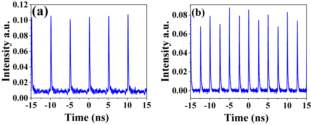
Figure 2 Pulse train of the seed (a) before and (b) after repetition rate doubling.
The seed laser is amplified by a PM pre-amplifier based on a 10/125 μm polarization-maintaining ytterbium-doped fiber (PM-YDF), delivering 49.6 W output power. A fast-axis-blocked PM circulator is used in the TMI mitigation experiments for polarization extinction ratio optimization.
The main amplifier adopts a similar cladding-pumped structure. A mode-field adapter (MFA) ensures efficient coupling between the 10/125 and the 20/400 μm PM fibers. A 13 m PM-YDF (20/400 μm core/cladding, NA = 0.065) is coiled in a figure-of-eight groove with 11 cm inner diameter, with a cladding absorption coefficient of 1.45 dB/m at 976 nm. Two 870 W laser diodes (LDs) at 976 nm are combined via a (6 + 1) ×1 PM combiner to provide pump light. A cladding power stripper (CPS) is employed to remove residual pump light.
Finally, the output laser of the main amplifier is injected into a piece of 15 m polarization-maintaining germanium-doped fiber (PM-GDF) with the core/cladding diameters of 20/400 μm for broadband supercontinuum generation. This germanium-doped fiber (GDF) is coiled around an aluminum cylinder with a 23 cm diameter. A quartz block head is employed to mitigate the back-reflected light.
3 Results and discussion
3.1 Mitigation of the TMI effect
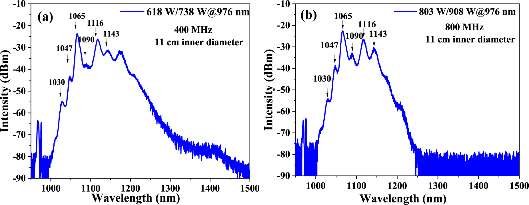
Figure 3 presents the output properties of the main amplifier. Figure 3(a) demonstrates the spectral evolution, where the spectrum broadens to cover 1000–1500 nm at 620 W output power. Beyond this power level, further pump power increase no longer produces spectral broadening but instead induces spectral fluctuations. Figure 3(b) shows the output power scaling with the pump power. The power initially increases linearly with the pump power. However, when the output power reaches 620 W, the output power no longer increases with the pump power, as shown with the blue dot in Figure 4(b) (at a pump power of 738 W, the output power is 618 W).
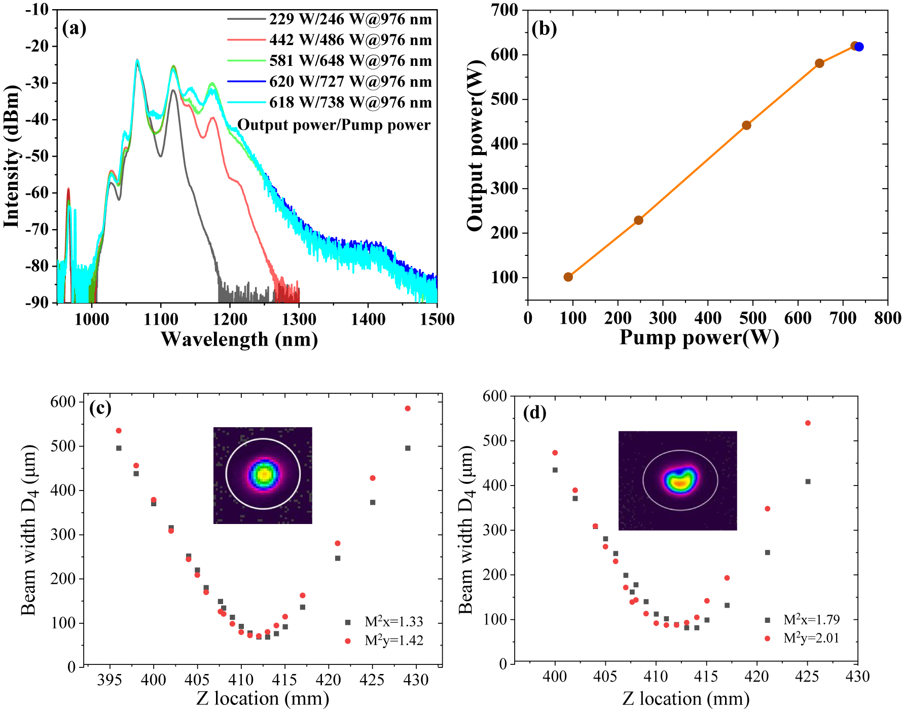
Figure 3 The output properties of the main amplifier with 400 MHz repetition rate: (a) spectral evolution (the legend presents output power/pump power and all spectral figures follow this convention); (b) output power; beam quality at (c) 581 W (inset: beam profile) and (d) 620 W (inset: beam profile).

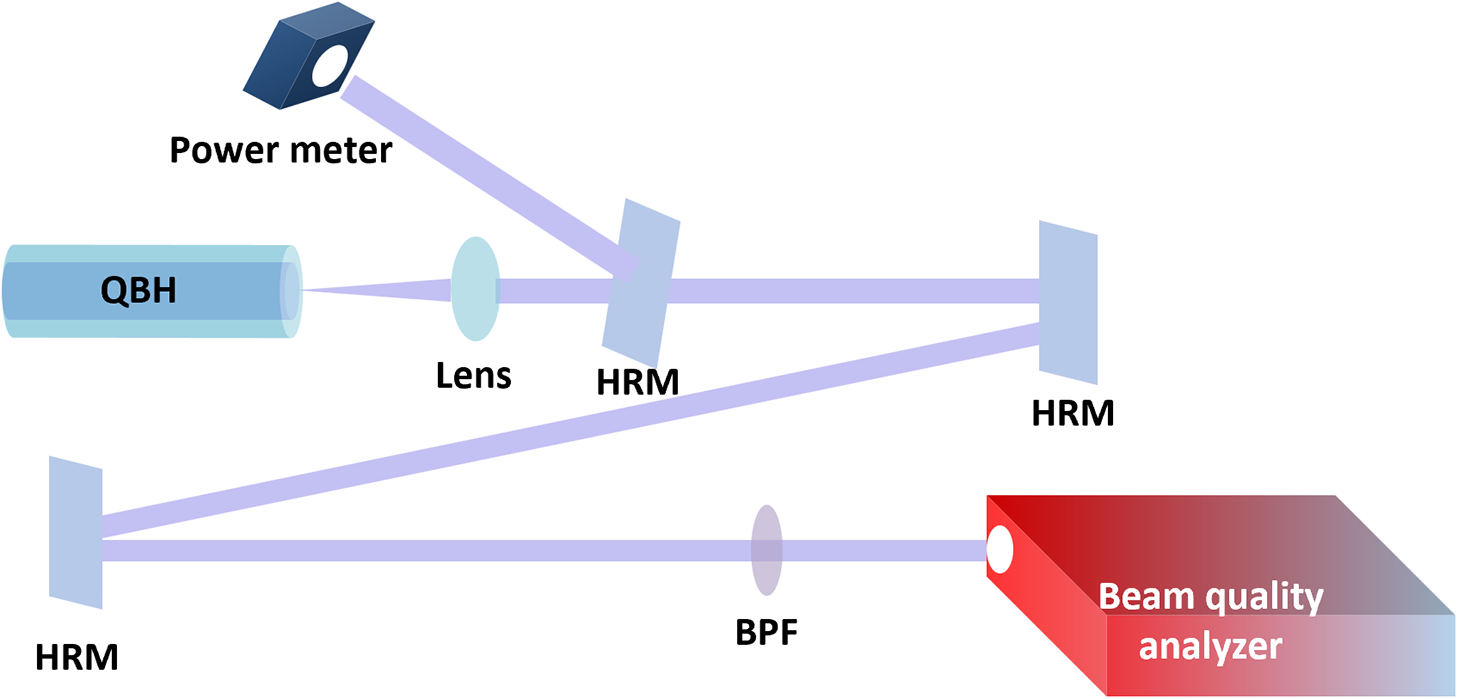
Figure 4 Schematic diagram of the beam quality measurement. HRM, high-reflection mirror; BPF, band pass filter.
The modal characteristics of the amplifier were assessed by measuring the M 2 factor at 1064 nm. The schematic diagram of this measurement is shown in Figure 4. The output beam was collimated using a lens with a 3 cm focal length and incident on a high-reflection (HR) mirror (99% reflectance over the 400–1200 nm range). To safeguard the beam quality analyzer, only the weak transmitted portion (<1%) of the beam was employed for subsequent measurements. This transmitted beam was then reflected by two additional HR mirrors, which not only facilitated beam path alignment but also suppressed residual light with wavelengths above 1200 nm. Finally, the beam underwent spectral purification using a 1064 nm bandpass filter (5 nm bandwidth with an optical density >5). The spectrally purified beam was subsequently captured and analyzed by the beam quality analyzer to determine the M 2 factor.
Figures 3(c) and 3(d) present the M 2 factors and beam profiles at output powers of 581 and 620 W, respectively. The M 2 values increased from 1.33 (x-direction) and 1.42 (y-direction) at 581 W to 1.79 and 2.01 at 620 W. The saturation phenomenon in output power, accompanied by the degradation of beam quality, clearly signifies the onset of TMI. To further scale the output power, effective TMI mitigation methods need to be implemented.
To investigate the relationship between spectral broadening and the TMI threshold, additional repetition rate doubling was implemented. The repetition rate was increased to 800 MHz, which effectively reduced peak power and weakened the spectral broadening. Figure 5(a) presents the spectra of the main amplifier with 800 MHz repetition rate. The spectrum covers 1000–1250 nm at 803 W output power. This demonstration leads to a 29.5% increase in TMI threshold (from 620 to 803 W). The reduction of peak power suppresses the generation of nonlinear effects, while reducing the quantum defect-induced thermal loading in the fiber core, thereby increasing the TMI threshold.
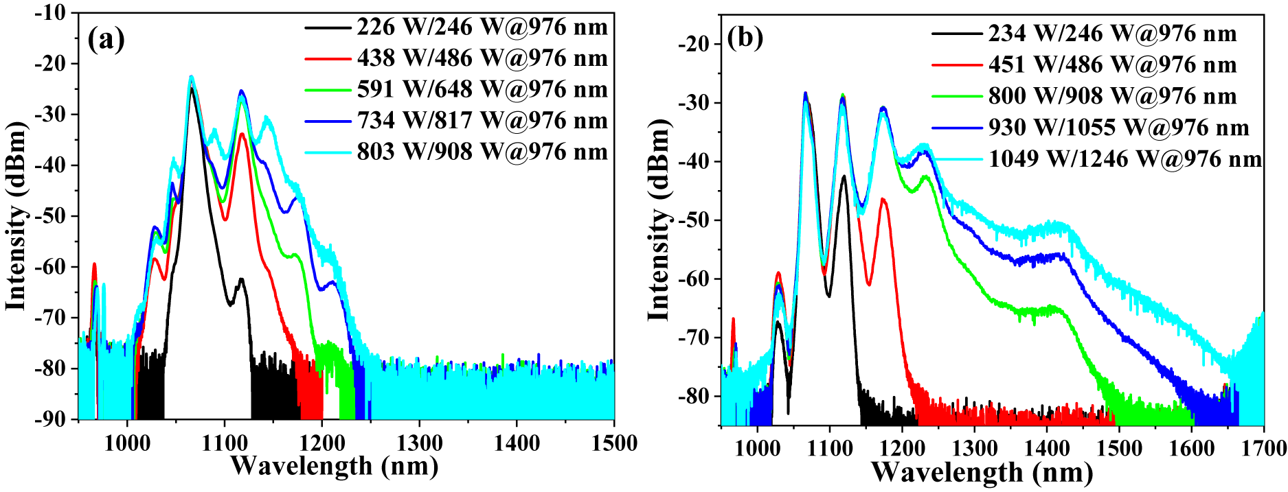
Figure 5 The output spectra of the main amplifier with 800 MHz repetition rate. (a) The gain fiber is coiled in a figure-of-eight groove with 11 cm inner diameter and (b) 8 cm inner diameter.
Previous studies had demonstrated that increasing the loss of HOM can effectively raise the TMI threshold[ Reference Wu, Li, An, Li, Chen, Xiao, Huang, Yang, Yan, Leng, Pan and Zhou 30 , Reference Ma, Xiao, Liu, Zhang, Wang, Leng and Zhou 36 ]. To optimize the mode property, the PM-YDF was coiled into a figure-of-eight groove (see inset in Figure 1) with a smaller inner diameter, from 11 to 8 cm. As shown in Figure 5(b), this tighter coiling results in an increasement in TMI threshold from 803 to 1049 W and further spectral broadening (extending to 1650 nm). The improved performance was attributed to the stronger bend-induced HOM loss, which mitigated the generation of an MIP and thus raised the TMI threshold.
To explore the correlation between the polarization state and TMI threshold, a PM circulator with fast-axis-blocking capability was implemented, which increased the polarization extinction ratio of the pre-amplifier output from 17.4 to 24.0 dB. As shown in Figure 6(a), this polarization optimization resulted in an 83 W increase of TMI threshold (from 1049 to 1132 W), while causing negligible spectral broadening. The principle of the circulator’s fast-axis-blocking function is based on its internal free-space optical path design, where a polarizing beam splitter reflects and filters out the fast-axis component and optimizes the polarization extinction ratio of the pre-amplifier. To date, no studies have explicitly indicated the influence of the signal polarization extinction ratio on TMI effects. However, several reports suggest that thermally induced polarization coupling in high-power linearly polarized amplifiers may excite higher-order modes[ Reference Wu, Yan, Li, Li, Chen, Gong and Xiao 37 , Reference Wu, Yan, Li, Wang, Gong and Xiao 38 ]. The optimization of the signal polarization extinction ratio could suppress such thermally induced polarization coupling, thereby mitigating HOM generation. This mechanism may explain the observed enhancement in TMI threshold with polarization extinction ratio optimization.

Figure 6 The output properties of the main amplifier after polarization extinction ratio enhancement: (a) spectral evolution; (b) output average power (inset: the CPS’s temperature versus pump power); beam quality at (c) 1049 W (inset: beam profile) and (d) 1132 W (inset: beam profile).
3.2 Manifestations of TMI in supercontinuum generation
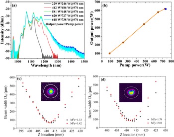
Figures 6(a)–6(d) illustrate the spectral evolution, power characteristics, temperature of the CPS and beam quality of the main amplifier after polarization extinction ratio enhancement. These aspects were investigated to explore the features of the TMI effect in supercontinuum generation. Comparing the spectra at 1132 and 1054 W in Figure 6(a), when the TMI effect occurs, burr-like spectral fluctuations were observed in the wavelength range of 1200–1650 nm. This phenomenon may be attributed to the millisecond-scale energy transfer between the FM and HOMs. When energy transfers to the FM, the energy density is higher, resulting in stronger nonlinear effects and a broader spectrum. Conversely, when energy transfers to HOMs, the weaker nonlinear effects result in a narrower spectrum. Due to the slower measurement of the optical spectrum analyzer, compared to the millisecond-scale energy transfer process, the measured spectrum is the result of the aforementioned fast process, which leads to burr-like spectral fluctuations. Similar burr-like spectral fluctuations have also been observed in Ref. [Reference Tao, Xiao, Zhang, Leng, Wang, Zhou and Xu26], where they suggest that TMI affects the generation of SRS, causing the Raman spectrum to become burr-like.
The blue dots in Figure 6(b) demonstrate that the M 2 is maintained below 1.8 at lower power levels but increases significantly after the onset of TMI. The M 2 values increase from 1.89 (x-axis) and 1.58 (y-axis) at 1049 W to 4.48 and 3.68 at 1132 W; the specific beam quality properties are shown in Figures 6(c) and 6(d).
The orange dots in Figure 6(b) demonstrate that the output power increases linearly until power saturation at 1354 W. Subsequently, the power decreases with further increases in pump power. Specifically, the output power decreases from 1132 to 1054 W with pump power increasing from 1354 to 1372 W.
In addition, after the onset of TMI and power saturation, the temperature of the CPS casing noticeably increased (from 31.1°C at 1132 W to 54.1°C at 1054 W). This is due to HOM generation and modal properties of the 20/400 μm PM-GDF used in the CPS. Parts of the HOMs cannot be confined within the fiber core and instead leak into the cladding, where they are subsequently stripped by the CPS, generating significant heat. Notably, HOMs with a longer wavelength exhibit higher leakage probabilities into the cladding, thereby intensifying the burr-like spectral fluctuations in the long-wavelength region.
3.3 Four-wave mixing phenomenon and broadband supercontinuum generation
In addition to the TMI effect, an interesting four-wave mixing phenomenon was experimentally observed. As shown in Figures 7(a) and 7(b), when the fiber is coiled with the minimum diameter of 11 cm, multiple spectral peaks at 1030, 1047, 1090 and 1143 nm emerge during the spectral broadening process. This effect occurs consistently irrespective of whether the repetition rate is 400 or 800 MHz.

Figure 7 Output spectra at inner diameter of 11 cm for (a) 400 MHz and (b) 800 MHz.
The spectral peak at 1030 nm arises from polarization mode four-wave mixing, occurring solely along the fast axis of the fiber. This phenomenon was also observed in our previous work[ Reference Li, Zhao, Li and Chen 25 ]. The spectral components at 1047, 1090 and 1143 nm result from intermodal four-wave mixing, which is a nonlinear process in multimode fibers where energy transfer and new frequency components are generated through phase-matched nonlinear coupling between different modes of optical fields[ Reference Swain and Venkitesh 39 – Reference Rehan, Chowdhury, Biswas, Kang and Varshney 42 ]. When the FM and HOM at the signal wavelength of 1064 nm meet the phase-matching conditions, intermodal four-wave mixing occurs, producing a 6.5 THz blue-shifted component at 1047 nm and a 6.5 THz red-shifted component at 1090 nm. Similarly, when the FM and HOM at the first-order Raman wavelength of 1116 nm satisfy the phase-matching conditions, a 6 THz blue-shifted component at 1090 nm and a 6 THz red-shifted component at 1143 nm are generated. When we coil the fiber into a figure-of-eight groove with inner diameter of 8 cm, the loss of the HOM is increased, and the intermodal four-wave mixing effect is suppressed, causing the spectral peaks at 1047, 1090 and 1143 nm to vanish, as depicted in Figure 6(a).
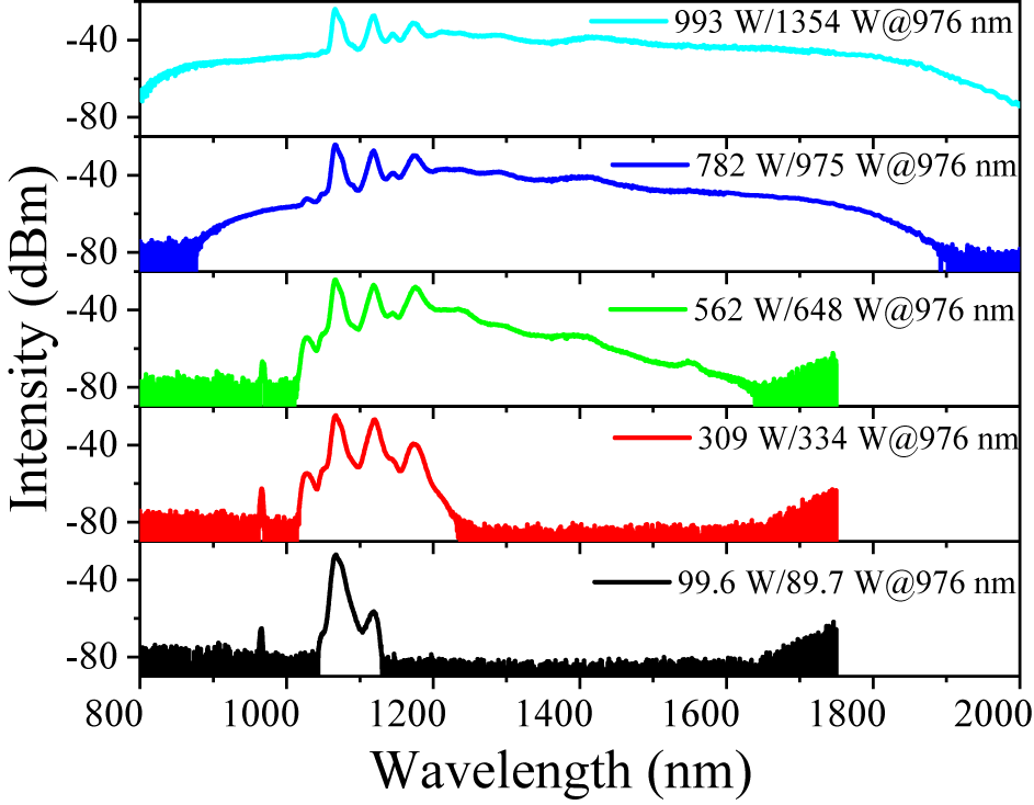
To achieve a broader supercontinuum, a 15-m-long PM-GDF was spliced to the output of the main amplifier. Figure 8 presents the output characteristics of the supercontinuum. Compared to the amplifier output, the supercontinuum exhibits broader spectral bandwidth but lower average power due to enhanced nonlinear effects. The pump power at which TMI occurs remains at 1354 W, consistent with the threshold observed in the main amplifier. This phenomenon indicates that the PM-GDF does not contribute to TMI, as the thermal load induced in the PM-GDF by nonlinear processes remains insufficient to trigger mode instability. At the maximum pump power of 1354 W, the system generates a 993 W linearly polarized supercontinuum spanning 800–2000 nm. To our knowledge, this is the highest power reported for a polarized supercontinuum source. However, further power scaling is still limited by TMI. To overcome this limitation, additional mitigation strategies, such as pump wavelength detuning to reduce quantum defect heating and optimized fiber design to suppress HOMs, should be implemented for higher power supercontinuum generation.

Figure 8 Spectral evolution of the linearly polarized supercontinuum.
4 Conclusion
This work introduces a high-power linearly polarized supercontinuum laser system, achieving a record power of 993 W with a broad spectrum ranging from 800 to 2000 nm. The TMI effect is observed during the supercontinuum generation for the first time, which shares common features with conventional lasers, including power-scaling limitation and beam quality degradation, while exhibiting broadband characteristics such as burr-like spectral fluctuations. Traditional bend loss method for HOM suppression is used to increase the TMI threshold. In particular, reducing the peak power to mitigate nonlinear thermal loading and utilizing a fast-axis-blocked PM-circulator to enhance the polarization extinction ratio and modal purity can also collectively increase the TMI threshold. These findings advance the understanding of nonlinearity-driven TMI dynamics in broadband systems and provide critical guidelines for power scaling in high-power supercontinuum lasers.
Acknowledgements
This work was supported by the National Natural Science Foundation of China (Grant No. 62205373).


 Open access