


Introduction
Myocardial biopsy is one of the most valuable diagnostic procedures for cardiomyopathy and for evaluation of rejection in post-heart transplant patients and is widely performed in both adults and children. Reference Cooper, Baughman and Feldman1 The complication rate of this procedure has been reported to range from less than 1% to 6%. Reference Burger, Richter, Classen, Schönburg, Choi and Ziegelhoeffer2 Complications include vascular injury, pneumothorax, vagal reflex, infection, arrhythmia, and ventricular perforation. Reference Edwards3,Reference Osterhaus, Vos and Balk4 Among these, serious complications such as ventricular perforation and cardiac tamponade occur in approximately 0.2–0.9% of cases. Reference Bermpeis, Esposito and Gallinoro5–Reference Deckers, Hare and Baughman7 Reported risk factors for these complications include operator and institutional experience, as well as patient-related conditions such as acute myocarditis and haemodynamic instability. Reference Pophal, Sigfusson and Booth6 Although myocardial biopsy is generally considered safe in stable post-transplant patients, cardiac tamponade has nevertheless been reported. Reference Bermpeis, Esposito and Gallinoro5–Reference Deckers, Hare and Baughman7 To avoid ventricular perforation, the tip of the biopsy forceps should be directed towards the ventricular septum under fluoroscopic guidance to obtain the specimen. One textbook Reference Moscucci8 recommends setting the fluoroscopy angle at 30° right anterior oblique or 60° left anterior oblique, but it can be difficult to determine whether the biopsy forceps are directed at the ventricular septum at the same fixed fluoroscopy angle when the orientation of the ventricular septum and the path of the biopsy forceps to the ventricular septum vary significantly from patient to patient. While a variety of ventricular septal orientations have been reported in adults, Reference Squara, Fourrier and Diascorn9 neither the orientation of the ventricular septum nor the angle between the biopsy forceps and the ventricular septum has been reported in paediatric patients. Particularly in paediatric post-heart transplant patients, variations in heart position may be greater than in adults due to the greater mismatch between recipient and donor body size, which may lead to greater variability in the ventricular septal orientation. Reference Singh, Colan and Gauvreau10
In recent years, the technique of placing ventricular pacing leads at the septum during transvenous implantation has been increasingly adopted to reduce the risks of ventricular perforation and cardiac tamponade, as well as to achieve more physiological pacing. Reference Shimony, Eisenberg, Filion and Amit11 It has been reported that pre-procedural CT imaging to adjust the left anterior oblique projection parallel to the septal plane for each patient is a safe and effective approach. Reference Squara, Scarlatti, Riccini, Collura, Caravati and Camporotondo12 Similarly, we employed a strategy of individually setting the angle of the fluoroscopy for each patient and ensuring that the myocardial biopsy forceps were precisely oriented toward the septum.
The aim of this study was to establish the fluoroscopic angles for determining from fluoroscopic images whether the biopsy forceps are facing the ventricular septum in paediatric patients by examining the angle of the ventricular septum to the sagittal plane during myocardial biopsy and the angle between the biopsy forceps and the ventricular septum.
Materials and methods
Patients
We retrospectively collected data on paediatric patients who underwent myocardial biopsy at the Department of Pediatrics, University of Tokyo Hospital, between January 2019 and June 2023. In cases where biopsy was performed more than once during the period, the first image performed was used as the reference for calculation. This retrospective study was approved by the University of Tokyo Hospital Ethics Committee on July 22, 2020 (No. 2701).
Evaluation of biopsy location and axis of the septum using thoracic CT and fluoroscopy
All patients underwent cardiac CT with protocol by Shirota et al. prior to myocardial biopsy as a routine clinical protocol. Reference Shirota, Maeda and Namiki13 Second-generation 320-row CT (Aquilion ONE™ / ViSION edition; Canon Medical Systems Corporation, Tochigi, Japan) with electrocardiogram-gated axial scans was used. Contrast enhancement material at 2 mL/kg body weight of 300 mgI/mL of iohexol was used, which was diluted by adding normal saline at one-half the volume of the material and injected at a rate of 0.5 mL/s for children <6 months or body weight <5 kg, and undiluted material was injected at a rate of 1.0 mL/s for the others. Images were reconstructed using MBIR (Forward projected model-based Iterative Reconstruction SoluTion (FIRST) in the “cardiac strong” mode) with the slice interval of 0.25 mm.
The angle (α) between the long axis of the ventricular septum, defined as the straight line connecting the apex to the membranous region, and the sagittal plane was calculated with reference to the axial CT image (Figure 1).
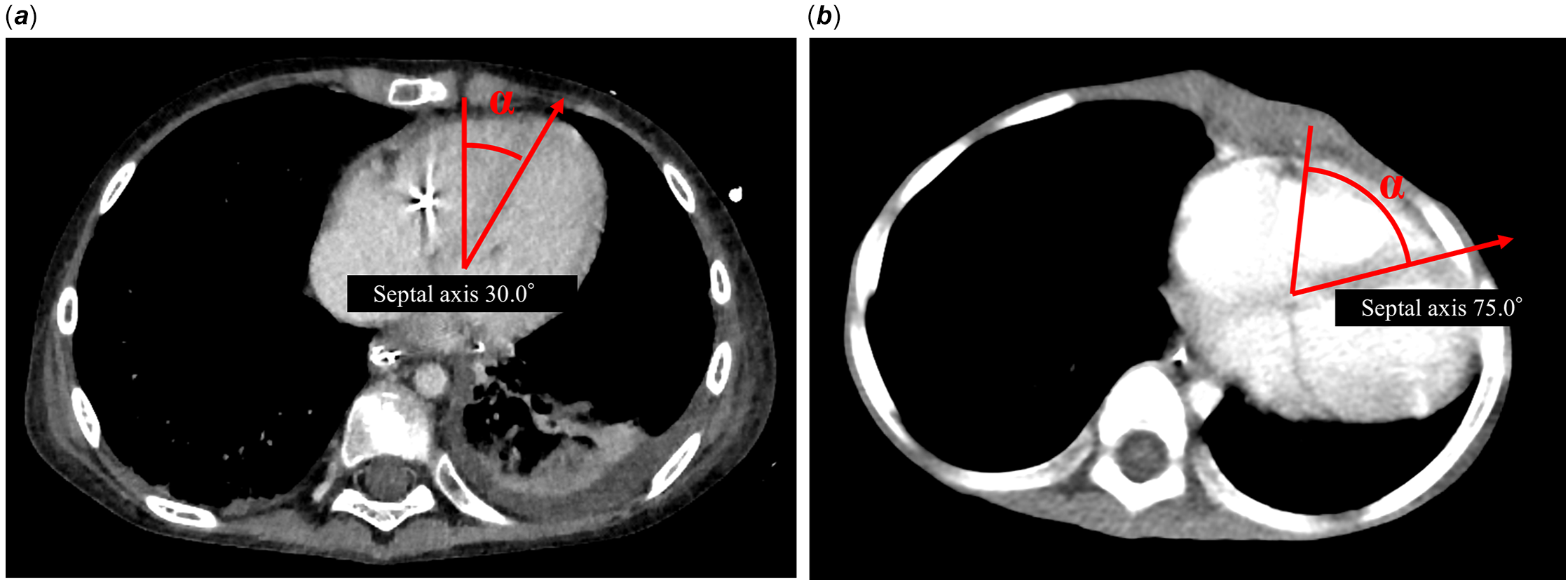
Figure 1. Variability of ventricular septum angle on contrast-enhanced CT. Contrast-enhanced computed tomography (CT) images showing parallel sections through the heart. Angle α is defined as the angle between a line connecting the apex of the heart to the membranous septal region and a perpendicular reference line. ( a ) Image from a case with the minimum angle α. ( b ) Image from a case with the maximum angle α.
Myocardial biopsy
All myocardial biopsies were performed under general anaesthesia. Patients were monitored with a 3-lead electrocardiogram, blood pressure monitoring, and SpO2. In larger patients, an 8 Fr sheath introducer (Radifocus introducer, Terumo Corporation, Tokyo, Japan) was placed in the right or left internal jugular vein, and a 6 Fr sheath introducer (Radifocus introducer, Terumo Corporation, Tokyo, Japan) was used in small patients. Using the angle between the sagittal plane and the ventricular septum measured with reference to the previous CT, the angle of the frontal fluoroscopy was set to the individualised left anterior oblique, and the angle of the lateral fluoroscopy was set to the individualised right anterior oblique. 0. 035“ 150 cm hydrophilic nitinol guidewire (Radifocus Guidewire M, Terumo Corporation, Tokyo, Japan) was placed in the peripheral pulmonary artery, and in patients with a 6 Fr sheath, the 6 Fr sheath was removed and a 6 Fr J catheter was inserted, after confirming that the tip of the J catheter introducer reached the right ventricle, the guidewire and inner tube of the J sheath were removed. Right ventriculography was performed from the J sheath to confirm septal position, and a 5.5 Fr biopsy forceps (Biopsy Forceps, Cordis, Chicago, US) was advanced from the sheath, with the sheath tip confirmed to be in the right ventricle by pressure monitoring. The biopsy was adjusted to direct the tip toward the septum using fluoroscopic images.
Calculation of the biopsy forceps angle
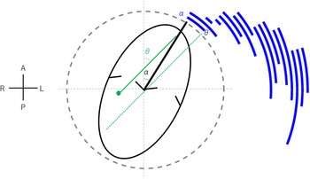
The angle between the biopsy forceps and the ventricular septum (β) was calculated from the image of the myocardial biopsy forceps facing the septum and being collected. Using the image of the individualised left anterior oblique and individualised right anterior oblique, the distance between the tip of the biopsy forceps and the part of the biopsy forceps that was at the same height as the tip of the biopsy forceps was A and B (Figure 2 a , b ). β was obtained from A and B using the following formula (Figure 2 c ).
 $$ \beta =\tan ^{-1} {B \over A} $$
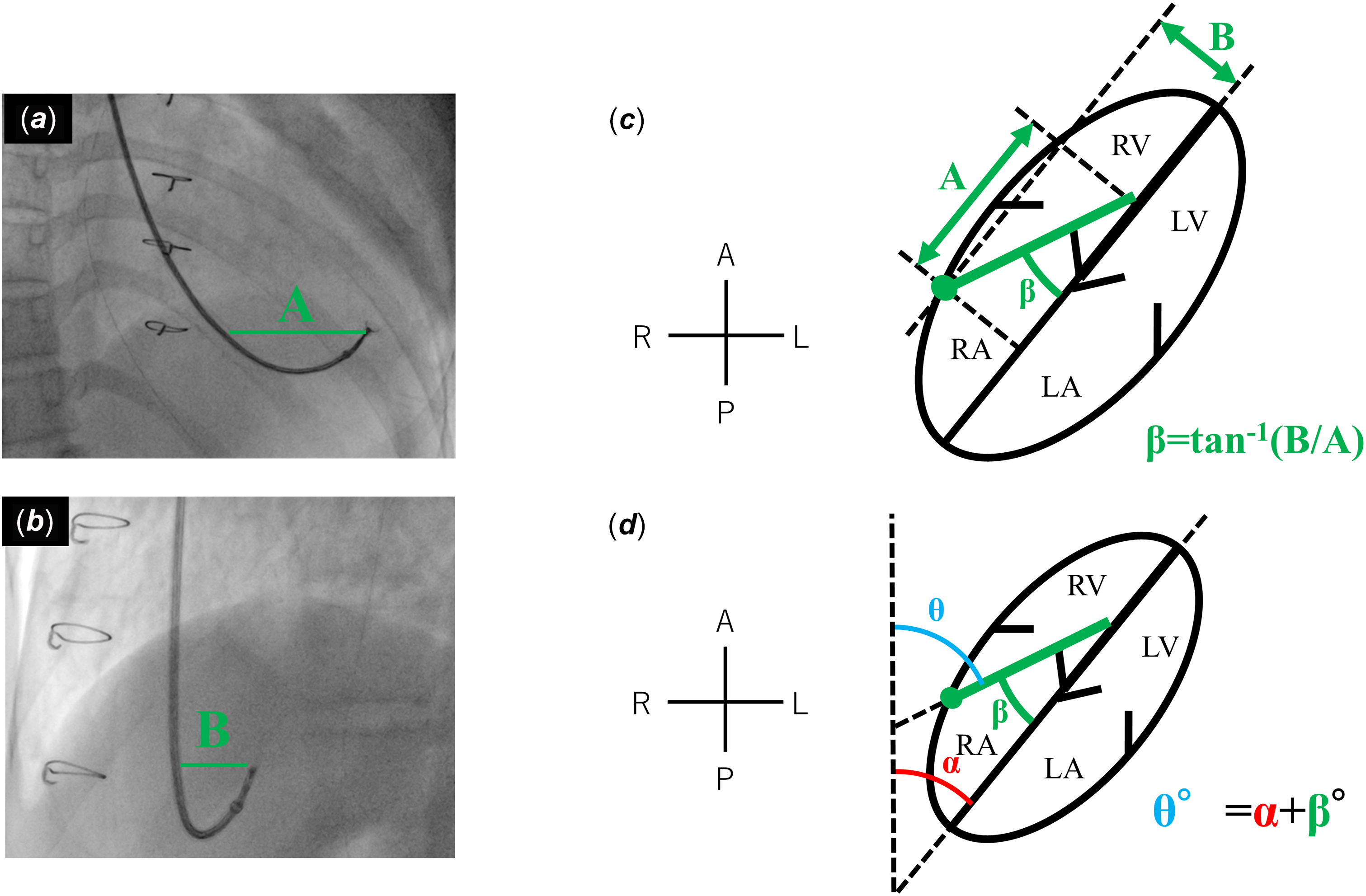
Figure 2. Adjustment of biopsy fluoroscopic angles based on CT measurements. Fluoroscopic images obtained during myocardial biopsy. The fluoroscopic angles were adjusted to the right anterior oblique and left anterior oblique views based on the ventricular septum orientation measured by preprocedural CT. ( a ) Fluoroscopic image taken in the right anterior oblique view. ( b ) Fluoroscopic image taken in the left anterior oblique view. The distances from the biopsy catheter to the biopsy forceps tip at the same height were defined as A (right anterior oblique) and B (left anterior oblique), respectively. ( c ) Schematic illustration depicting the calculation of angle β between the biopsy forceps and the ventricular septum, based on distances A and B. ( d ) Schematic illustration showing the calculation of angle θ between the biopsy forceps and the body axis, based on angle α and angle β. The ellipse represents the free wall of the heart, and the green dotted line indicates the biopsy forceps. Directions are indicated as A (anterior), P (posterior), R (right), and L (left). RA = Right Atrium; RV = Right Ventricle; LA = Left Atrium; LV = Left Ventricle.
 $$ \theta = \alpha + \beta $$
From α and β obtained above, the angle (θ) between the perpendicular line toward the spine and the biopsy forceps was calculated (Figure 2 d ).
Results
Myocardial biopsy was performed in 16 paediatric patients at our hospital between January 2019 and June 2023, resulting in a total of 85 biopsy procedures during the study period. No biopsies performed prior to the study period were included in this count. No patients had chest deformities or lung malformations that could affect cardiac position or orientation.
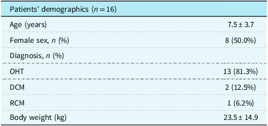
For the purposes of this study, only the first myocardial biopsy performed in each patient during the study period was selected for analysis to ensure consistency and to avoid bias associated with repeated procedures. A total of 13 were heart transplant patients, two had dilated cardiomyopathy and one had restrictive cardiomyopathy. The mean age at the time of myocardial biopsy was 7.5 years, and five patients were girls (Table 1).
Table 1. Baseline characteristics of the study population

OHT = orthotopic heart transplantation; DCM = dilated cardiomyopathy; RCM = restrictive cardiomyopathy.
The mean angle α (angle of the ventricular septum) was 54.3°, with a range of 30.0–75°. Figure 1 shows the two cases with the smallest and largest angle α imaged by CT. Angle β (the angle between the biopsy forceps and the ventricular septum) averaged 21.3° and ranged from 3.5 to 53.4°. Angle θ (angle between the biopsy forceps and the sagittal plane) averaged 75.6° and ranged from 45.0 to 115.7°. The acceptable range for individualised left anterior oblique is between θ and α, as will be discussed in the Discussion section, and Figure 3 shows the arc representing the range between angles θ and α calculated for each case.

Figure 3. Correlation between septum orientation and biopsy forceps direction. Composite plot illustrating the relationship between angle α (septal orientation) and angle θ (biopsy forceps direction relative to the body axis) for each patient. Directions are indicated as A (anterior), P (posterior), R (right), and L (left).
Of the 85 myocardial biopsies performed using this strategy, none resulted in ventricular perforation.
Discussion
This study is the first to demonstrate that cardiac rotation exhibits diverse variability in children and to illustrate the angles at which biopsy forceps are positioned during percutaneous myocardial biopsy. Individualised fluoroscopic angles during myocardial biopsy can ensure that biopsy forceps are directed to the septum, allowing for safe myocardial biopsy.
The angle of the interventricular septum in children varies significantly between individuals. In adults, the angle of the ventricular septum has been reported to be 39–74° based on CT or MRI results. Reference Squara, Fourrier and Diascorn9 In this study, it was found that the angle of the ventricular septum ranged from 30° to 75°, showing a slightly wider range compared to adults. Of the 16 cases studied, 13 were post-heart transplant patients. Generally, transplanted hearts in children have a wider range of donor-to-recipient body weight ratios (80–200%), Reference Singh, Colan and Gauvreau10 leading to significant variability in heart size relative to body size compared to adults. This variability is thought to be the reason for the broader range of ventricular septum angles observed in children compared to adults. Fluoroscopic angles should be determined on an individual basis during myocardial biopsy. In this study, it was found that both the angle of the ventricular septum (angle α) and the angle between the ventricular septum and the biopsy forceps (angle β) exhibited variability. As a result, the combined angle, which represents the angle of the biopsy forceps (angle θ), ranged widely from 45.0° to 115.7°.
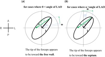
Adjusting the angle of the fluoroscopy for each individual is effective and safe when performing a myocardial biopsy. In adult patients, when placing a ventricular lead in the septum during pacemaker implantation, individual setting of the fluoroscopic angle based on prior contrast-enhanced CT images to ensure that the tip of the lead is facing the septum was demonstrated to be effective and safe. Reference Squara, Fourrier and Diascorn9,Reference Shimony, Eisenberg, Filion and Amit11 Similarly, in the present study, setting the fluoroscopic angle for each patient allowed the tip of the myocardial biopsy forceps to be displayed towards the septum rather than towards the right ventricular free wall, making it easier to adjust the tip position of the biopsy forceps during the procedure. Some textbooks Reference Moscucci8 state that the angle should be set at right anterior oblique 30° and left anterior oblique 60°. However, using these settings, the accurate positioning of the biopsy forceps tip may not be assessed in certain cases. If the fluoroscopic angle of the left anterior oblique view exceeds θ, the biopsy forceps tip appears to be directed toward the right side and the free wall when observed from the left anterior oblique view, even if it is actually oriented toward the septum. This misperception may complicate the decision to proceed with a biopsy (Figure 4 a ). Conversely, when the left anterior oblique angle is smaller than α, the biopsy forceps tip appears to be oriented toward the septum and the left side, despite its actual direction toward the free wall. In such cases, performing a biopsy under these conditions may increase the risk of cardiac tamponade (Figure 4 b ). Therefore, the optimal left anterior oblique angle must be maintained within the range of α to θ in all cases. The patient-specific α–θ range determined in this study is illustrated in Figure 3. As demonstrated, this range varies among individuals, and no single universal angle encompasses the α–θ range across all cases. Consequently, establishing a fixed fluoroscopic angle is impractical, and individualised angle selection is necessary to ensure procedural safety and accuracy.
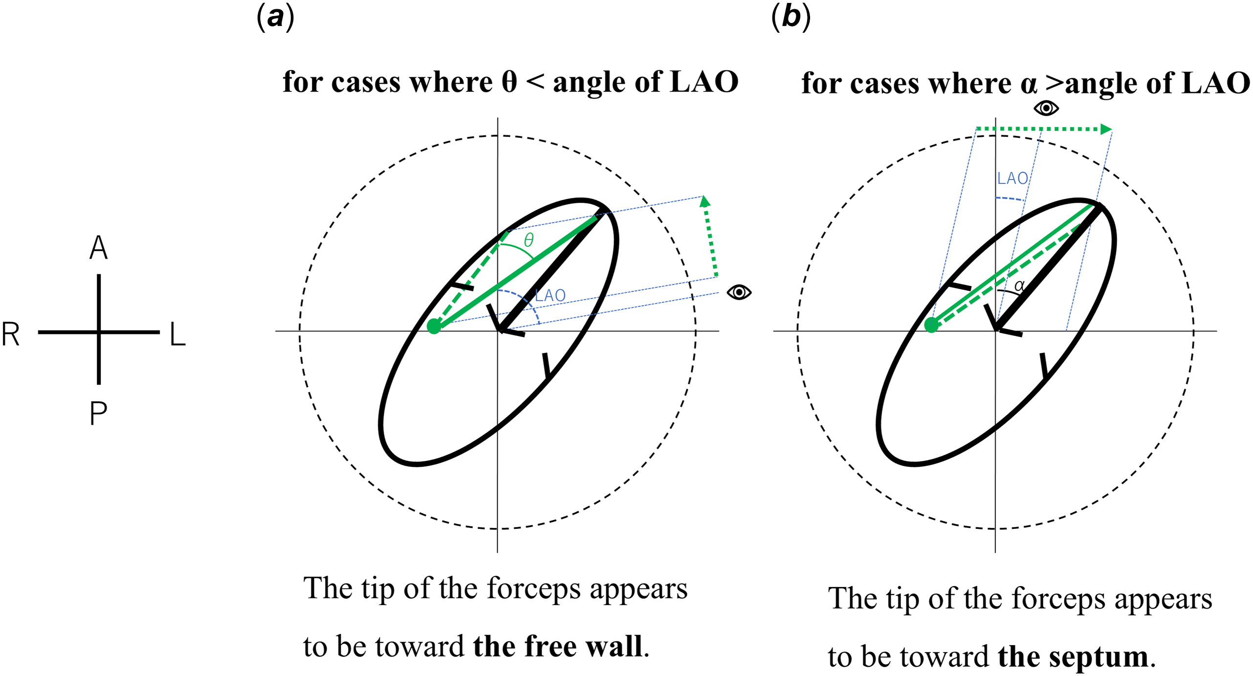
Figure 4. Mechanisms of misinterpretation in left anterior oblique fluoroscopic views. Schematic illustrations demonstrating misperception of the biopsy forceps tip direction under different fluoroscopic conditions. ( a ) When the left anterior oblique fluoroscopic angle is greater than θ, even if the biopsy forceps are directed toward the septum, the tip appears to be oriented toward the right side, mimicking a free wall orientation. ( b ) When the left anterior oblique fluoroscopic angle exceeds α, even if the biopsy forceps are directed toward the free wall, the tip appears oriented toward the left side, suggesting septal orientation. In both schematics, the ellipse represents the ventricular and atrial free wall, the solid line indicates the ventricular septum, the dot and line illustrate the biopsy forceps tip, and the dashed arrow shows the perceived direction of the tip in the left anterior oblique view. Directions are indicated as A (anterior), P (posterior), R (right), and L (left). LAO = Left Anterior Oblique.
Previous reports have described methods using echocardiographic guidance to verify biopsy forceps orientation toward the septum. Transthoracic echocardiography guidance has been associated with cases of ventricular perforation. Reference Blomström-Lundqvist, Noor, Eskilsson and Persson14 Transesophageal echocardiography, with its superior resolution, has shown promise in small studies, with no perforations reported. Reference Kawauchi, Gundry, Boucek, de Begona, Vigesaa and Bailey15 However, transesophageal echocardiography guidance has practical limitations, including restricted visualisation of the entire chamber, inconsistent identification of the forceps tip, and the need for additional personnel to operate the system. Reference Silvestry, Kerber and Brook16 Therefore, fluoroscopic angle optimisation remains an important complementary approach. It is advisable to confirm the angle between the ventricular septum and the sagittal plane and to set the appropriate fluoroscopic angles parallel and perpendicular to the ventricular septum for each case. Using the fluoroscopic image as a reference, the biopsy site can be determined. Specifically, in left anterior oblique, parallel fluoroscopic images relative to the ventricular septum, the tip of the biopsy forceps being on the right side of the image confirms that it is not directed toward the free wall. In individualised right anterior oblique view, with fluoroscopic images taken perpendicular to the ventricular septum, the position of the biopsy forceps on the septum can be accurately identified.
The present study has several limitations. First, this is a single-centre study with a small sample size. Second, the ventricular septum is actually curved, Reference Triposkiadis, Xanthopoulos and Boudoulas17 but in this study, it was treated as a flat plane, and due to the tilt of the heart, the measured angle β may differ slightly from the actual angle. However, despite minor differences, when the biopsy forceps are directed to the right side in the individual’s left anterior oblique view, it can be considered a reliable indication that the biopsy forceps are properly oriented toward the septum.
Conclusion
The angle between the ventricular septum and the sagittal plane varies in each case in children. To accurately confirm that the tip of the biopsy forceps is correctly directed toward the ventricular septum during myocardial biopsy, it is advisable to use a fluoroscopic angle that is parallel and perpendicular to the ventricular septum for each case.
Acknowledgements
None.
Financial support
None.
Competing interests
None.
Ethical standards
The authors assert that all procedures contributing to this work comply with the ethical standards of the relevant national guidelines on human experimentation and with the Helsinki Declaration of 1975, as revised in 2008, and have been approved by the institutional committees (University of Tokyo Hospital Ethics Committee, Approval No. 2701).


 Open access