I. INTRODUCTION
Filter banks and transforms are essential components of signal processing and there are a wide variety of applications such as compression, communication, denoising, restoration and feature extraction [Reference Rao and Yip1–Reference Vetterli and Kovaĉević4]. For example, discrete cosine transform (DCT) and discrete wavelet transform (DWT) are popularly used in image and video processing. DCT is adopted by JPEG, MPEG-2, and MPEG4/AVC, while DWT is adopted by JPEG2000 and used for digital cinema [Reference Rao and Yip1,Reference Taubman and Marcellin2]. These transforms, however, have a disadvantage in representing diagonal edges and textures due to the separability. From this background, development of image transforms involves non-separable construction for handling such diagonal structures [Reference Vetterli5–Reference Muramatsu, Yamada and Kiya7]. The oversampled (OS) property is important as well as the non-separable property. Let us assume a P -channel filter bank. We denote the p th channel down- and upsampling factors as M
p
. Then the sampling ratio of the p th channel, M
p
, is given by
![]() $M_{p} = \vert \det ({\bf M}_{p})\vert$
. The total sum of the reciprocals of
$M_{p} = \vert \det ({\bf M}_{p})\vert$
. The total sum of the reciprocals of
![]() $\{M_{p}\}_{p=0}^{P-1}$
, that is,
$\{M_{p}\}_{p=0}^{P-1}$
, that is, $\sum^{P-1}_{p=0} {1 \over M_{p}}$
is called redundancy
![]() ${\cal R}$
. When
${\cal R}$
. When
![]() ${\cal R} = 1$
, the system is referred to as a critically sampled (CS) filter bank. The other case,
${\cal R} = 1$
, the system is referred to as a critically sampled (CS) filter bank. The other case,
![]() $ {\cal R} \gt 1$
, is called an OS filter bank. Advantage of OS filter bank is its high degree of design freedom [57–Reference Starck, Murtagh and Fadili10]. There is infinite combination of analysis and synthesis banks in the OS case, while a CS system has unique combination.
$ {\cal R} \gt 1$
, is called an OS filter bank. Advantage of OS filter bank is its high degree of design freedom [57–Reference Starck, Murtagh and Fadili10]. There is infinite combination of analysis and synthesis banks in the OS case, while a CS system has unique combination.
Two simple ways are well known to construct OS filter banks from CS ones. One is a mixture construction of multiple CS systems, and the other is an undecimated, or shift-invariant construction, which is realized by removing the downsamplers and upsamplers from a CS system [Reference Starck, Murtagh and Fadili10,Reference Muramatsu, Han, Kobayashi and Kikuchi11]. The redundancy
![]() ${\cal R}$
is, however, restricted to be integer in these approaches. In particular, the undecimated approach tends to have high redundancy. Undecimated Haar transform and Contourlets are known as OS systems. Undecimated Haar transform satisfies OS, linear-phase (LP) and paraunitary (PU) property, but does not have the non-separable property. On the other hand, Contourlets can satisfy the non-separable and OS property. However, simultaneous realization of the LP and PU property is restrictive due to the structure [Reference Do and Vetterli9]. In general, the higher the redundancy is, the larger the computation and memory consumption become. From the fact, lower redundancy is requested while maintaining preferable properties for image processing. The authors have proposed two-dimensional (2D) non-separable oversampled lapped transforms (NSOLTs) as a new transform [Reference Muramatsu and Aizawa12]. The transform is non-separable and can simultaneously satisfy the OS, compact-supported, LP, tight-frame, symmetric, real-valued, and overlapped property. NSOLTs are also equipped with no-DC-leakage option. The redundancy can be controlled flexibly by the number of channels P and the sampling ratio M. NSOLTs with redundancy less than two were shown to be superior or comparable with the undecimated Haar wavelet transform in terms of image restoration performance [Reference Muramatsu and Aizawa12,Reference Muramatsu and Aizawa13]. It is also possible to apply a learning-based dictionary design [Reference Muramatsu14]. NSOLTs are verified to have comparable or superior sparse representation performance to Sparse K-SVD [Reference Rubinstein, Zibulevsky and Elad15].
${\cal R}$
is, however, restricted to be integer in these approaches. In particular, the undecimated approach tends to have high redundancy. Undecimated Haar transform and Contourlets are known as OS systems. Undecimated Haar transform satisfies OS, linear-phase (LP) and paraunitary (PU) property, but does not have the non-separable property. On the other hand, Contourlets can satisfy the non-separable and OS property. However, simultaneous realization of the LP and PU property is restrictive due to the structure [Reference Do and Vetterli9]. In general, the higher the redundancy is, the larger the computation and memory consumption become. From the fact, lower redundancy is requested while maintaining preferable properties for image processing. The authors have proposed two-dimensional (2D) non-separable oversampled lapped transforms (NSOLTs) as a new transform [Reference Muramatsu and Aizawa12]. The transform is non-separable and can simultaneously satisfy the OS, compact-supported, LP, tight-frame, symmetric, real-valued, and overlapped property. NSOLTs are also equipped with no-DC-leakage option. The redundancy can be controlled flexibly by the number of channels P and the sampling ratio M. NSOLTs with redundancy less than two were shown to be superior or comparable with the undecimated Haar wavelet transform in terms of image restoration performance [Reference Muramatsu and Aizawa12,Reference Muramatsu and Aizawa13]. It is also possible to apply a learning-based dictionary design [Reference Muramatsu14]. NSOLTs are verified to have comparable or superior sparse representation performance to Sparse K-SVD [Reference Rubinstein, Zibulevsky and Elad15].
Managing the boundary is one of important issues in the image-processing applications, in order to reduce the boundary distortion. Note that the symmetric extension method is no longer applicable to NSOLTs unless the fourfold symmetry is imposed on every atom [Reference Kiya, Nishikawa and Iwahashi16–Reference Muramatsu, Yamada and Kiya18]. Although the periodic extension (PE) method can take the place of the symmetric extension method, it has drawbacks of wrapping effects and global memory access requirement at the border. We adopt a different approach for NSOLTs. In [Reference Muramatsu, Kobayashi, Hiki and Kikuchi19,Reference Muramatsu and Hiki20], we have proposed a basis termination (BT) technique for non-separable CS lapped transforms, where the numbers of symmetric and anti-symmetric channels are restricted to be the same as each other. In this paper, we extend the BT technique for NSOLTs, i.e. the OS case, and propose a new technique which can deal with more general configuration. We refer to the proposed method as atom termination (AT) since NSOLTs are OS and the term “basis” is no longer appropriate.
The proposed technique is shown to serve variability of atoms block by block without any violation to the perfect reconstruction. It is also shown that a special selection of the lattice parameters breaks off an overlapping relation between neighboring blocks locally. By applying this property at the border, we can realize the AT.
This paper is an extended version of the conference paper [Reference Furuya, Hara and Muramatsu21]. The performance evaluation is revised to use the iterative hard thresholding (IHT) algorithm [Reference Blumensath and Davies22,Reference Blumensath and Davies23] in order to decrease the influence of selection of a dual analysis dictionary. This paper is organized as follows: in Section II, as a preliminary, the lattice structure of 2D NSOLT is briefly reviewed. Section III derives the blockwise implementation technique for the lattice structure and the boundary operation with AT. Then, Section IV verifies the significance of the proposed method through experimental results with the IHT for some standard images, followed by conclusions in Section V.
II. REVIEW OF 2D NSOLT
NSOLT is a lattice structure realization of 2D non-separable oversampled linear-phase perfect reconstruction filter bank (NS-OSLPPRFB). Let us review the lattice structure of NSOLT.
First, we summarize some symbols and notations used throughout this paper. M
y
and M
x
are reserved for decimation factors in the vertical and horizontal directions, respectively. The total decimation factor is given by
![]() $M = M_{y} \times M_{x}$
. As a preliminary, we define a P×P butterfly matrix B
P
(m) as
$M = M_{y} \times M_{x}$
. As a preliminary, we define a P×P butterfly matrix B
P
(m) as
 $${\bf B}_{P}^{(m)} = \left\{\matrix{{1 \over \sqrt{2}} \left(\matrix{{\bf I}_{m} & {\bf I}_{m} \cr {\bf I}_{m} & -{\bf I}_{m}} \right), \hfill &\displaystyle m = {P \over 2}, \cr {1 \over \sqrt{2}} \left(\matrix{{\bf I}_{m} & {\bf O} & {\bf I}_{m} \cr {\bf O} & \sqrt{2}{\bf I}_{P-2m} & {\bf O} \cr {\bf I}_{m} & {\bf O} & -{\bf I}_{m}} \right), \hfill &\displaystyle m \lt {P \over 2},} \right.$$
where
![]() $ \lceil M/2 \rceil \leq m \leq \lfloor P/2 \rfloor.\lceil \cdot \rceil$
and
$ \lceil M/2 \rceil \leq m \leq \lfloor P/2 \rfloor.\lceil \cdot \rceil$
and
![]() $\lfloor \cdot \rfloor$
are the ceiling function and the floor function, respectively.
$\lfloor \cdot \rfloor$
are the ceiling function and the floor function, respectively.
Through out this paper, symbols O and I
m
are reserved for the null and m×m identity matrix, respectively, where subscript m is omitted unless it is significant. A product of sequential matrices is denoted by
![]() $\Pi_{n = 1}^{N} {\bf A}_{n} = {\bf A}_{N}{\bf A}_{N - 1} {\bf A}_{N - 2} \cdots {\bf A}_{2} {\bf A}_{1}$
.
$\Pi_{n = 1}^{N} {\bf A}_{n} = {\bf A}_{N}{\bf A}_{N - 1} {\bf A}_{N - 2} \cdots {\bf A}_{2} {\bf A}_{1}$
.
A) Lattice structure of 2D NSOLT
In the article [Reference Muramatsu, Yamada and Kiya7], we showed a method to construct multidimensional non-separable linear-phase paraunitary filter banks (NS-LPPUFBs) with a lattice structure, and then, in [Reference Gan and Ma24], Gan and Ma showed the reduced parameterization. NSOLT is an extension of [Reference Muramatsu, Yamada and Kiya7] to the OS case and can simultaneously hold the OS, compact-support, symmetric, real-valued, and overlapped property. It can also satisfy the PU property and realize a Parseval tight-frame. NSOLT is categorized into two types as:
-
• Type-I: p s =p a ,
-
• Type-II: p s ≠p a ,
where p s and p a denote the numbers of symmetric and antisymmetric atoms, respectively.
1) Type-I NSOLT
Figure 1(a) shows an example of Type-I NSOLT lattice structure. When the number of channels P is even, it is possible to set p s =p a =P/2. The polyphase matrix of Type-I NSOLT has the following product form:
 $${\bf E}({\bf z}) = \prod_{n_{y} = 1}^{N_{y}} \{{\bf R}_{n_{y}}^{\{{y}\}}{\bf Q}(z_{y})\} \prod_{n_{x} = 1}^{N_{x}} \{{\bf R}_{n_{x}}^{\{{x}\}}{\bf Q}(z_{x})\}{\bf R}_{0}{\bf E}_{0}, $$
where
 $$\eqalign{{\bf Q}(z_{d}) & = {\bf B}_{P}^{(P/2)} \left(\matrix{{\bf I}_{p_{s}} & {\bf O} \cr {\bf O} & z_{d}^{-1}{\bf I}_{p_{a}}} \right) {\bf B}_{P}^{(P/2)}, \cr {\bf R}_{n}^{\{d\}} &= \left(\matrix{{\bf I}_{p_{s}} &{\bf O} \cr {\bf O} &{\bf U}_{n}^{\{d\}}} \right),}$$
where
![]() ${\bf U}_{n}^{\{d\}} \in {\open R}^{p_{a} \times p_{a}}$
is an arbitrary non-singular matrix. We adopt the initial matrix defined by the product of the matrix representation of 2D DCT
${\bf U}_{n}^{\{d\}} \in {\open R}^{p_{a} \times p_{a}}$
is an arbitrary non-singular matrix. We adopt the initial matrix defined by the product of the matrix representation of 2D DCT
![]() ${\bf E}_{0} \in {\open R}^{M \times M}$
and
${\bf E}_{0} \in {\open R}^{M \times M}$
and
 $${\bf R}_{0} = \left(\matrix{{\bf W}_{0} & {\bf O} \cr {\bf O} & {\bf U}_{0}} \right) \left(\matrix{{\bf I}_{\lceil M/2 \rceil} &{\bf O} \cr {\bf O} &{\bf O} \cr {\bf O} &{\bf I}_{\lfloor M/2 \rfloor} \cr {\bf O} &{\bf O}} \right) \in {\open R}^{P \times M}, $$
where
![]() ${\bf W}_{0} \in {\open R}^{p_{s} \times p_{s}}$
and
${\bf W}_{0} \in {\open R}^{p_{s} \times p_{s}}$
and
![]() ${\bf U}_{0} \in {\open R}^{p_{a} \times p_{a}}$
are arbitrary non-singular matrices. The matrices
${\bf U}_{0} \in {\open R}^{p_{a} \times p_{a}}$
are arbitrary non-singular matrices. The matrices
![]() $\{{\bf R}_{n}^{\{d\}}{\bf Q}(z_{d})\}$
realize the support extension of atoms, i.e., overlapping of atoms.
$\{{\bf R}_{n}^{\{d\}}{\bf Q}(z_{d})\}$
realize the support extension of atoms, i.e., overlapping of atoms.

Fig. 1. Types I and II lattice structure of analysis NSOLT, where E
0 denotes symmetric orthonormal transform matrix directly given by 2-D DCT, and W
0, U
0,
![]() ${\bf U}_{n}^{\{d\}}$
,
${\bf U}_{n}^{\{d\}}$
,
![]() ${\bf U}_{\ell}^{\{d\}}$
and
${\bf U}_{\ell}^{\{d\}}$
and
![]() ${\bf W}_{\ell}^{\{d\}}$
are arbitrary invertible matrices. N
d
is the order of the polyphase matrix in the direction d∈{y, x}, and d(z) is the delay chain determined by the downsampling factor M=diag(M
y
, M
x
). (a) Example of Type-I NSOLT. (#Channels P=6, Sampling factor M=4)], (b) Example of Type II NSOLT. (#Channels P=7, Sampling factor M=4, p
s
>p
a
).
${\bf W}_{\ell}^{\{d\}}$
are arbitrary invertible matrices. N
d
is the order of the polyphase matrix in the direction d∈{y, x}, and d(z) is the delay chain determined by the downsampling factor M=diag(M
y
, M
x
). (a) Example of Type-I NSOLT. (#Channels P=6, Sampling factor M=4)], (b) Example of Type II NSOLT. (#Channels P=7, Sampling factor M=4, p
s
>p
a
).
2) Type-II NSOLT
Figure 1(b) shows an example of Type-II NSOLT lattice structure. Type-II NSOLT is given when p s ≠p a . We here consider only the case p s >p a with even N y and even N x . The polyphase matrix E(z) of Type-II is represented by the following product form:
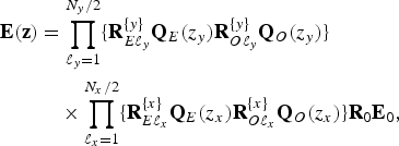 $$\eqalign{{\bf E}({\bf z}) &= \prod_{\ell_{y} = 1}^{{N_{y}}/{2}} \lcub {\bf R}_{E\ell_{y}}^{\{{y}\}}{\bf Q}_{E}(z_{y}) {\bf R}_{O\ell_{y}}^{\{{y}\}}{\bf Q}_{O}(z_{y})\rcub \cr &\quad \times \prod_{\ell_{x} = 1}^{{N_{x}}/{2}} \lcub {\bf R}_{E\ell_{x}}^{\{{x}\}}{\bf Q}_{E}(z_{x}){\bf R}_{O\ell_{x}}^{\{{x}\}} {\bf Q}_{O}(z_{x})\rcub {\bf R}_{0}{\bf E}_{0},} $$
where
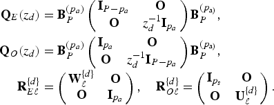 $$\eqalign{{\bf Q}_{E}(z_{d}) &= {\bf B}_{P}^{(p_{a})} \left(\matrix{{\bf I}_{P-p_{a}} & {\bf O} \cr {\bf O} & z_d^{-1}{\bf I}_{p_{a}}} \right) {\bf B}_{P}^{(p_{\rm a)}},\cr {\bf Q}_{O}(z_{d}) &= {\bf B}_{P}^{(p_{a})} \left(\matrix{{\bf I}_{p_{a}} &{\bf O} \cr {\bf O} &z_d^{-1} {\bf I}_{P - p_{a}}} \right) {\bf B}_{P}^{(p_{\rm a)}}, \cr {\bf R}_{E\ell}^{\{d\}} &= \left(\matrix{{\bf W}_{\ell}^{\{d\}} &{\bf O} \cr {\bf O} &{\bf I}_{p_{a}}} \right), \quad {\bf R}_{O\ell}^{\{d\}} = \left(\matrix{{\bf I}_{p_{s}}& {\bf O} \cr {\bf O} & {\bf U}_{\ell}^{\{d\}}} \right).}$$
![]() ${\bf W}_{\ell}^{\{d\}} \in {\open R}^{p_{s} \times p_{s}}$
and
${\bf W}_{\ell}^{\{d\}} \in {\open R}^{p_{s} \times p_{s}}$
and
![]() ${\bf U}_{\ell}^{\{d\}} \in {\open R}^{p_{a} \times p_{a}}$
are arbitrary invertible matrices. We adopt the initial matrix defined by the product of the 2D DCT
${\bf U}_{\ell}^{\{d\}} \in {\open R}^{p_{a} \times p_{a}}$
are arbitrary invertible matrices. We adopt the initial matrix defined by the product of the 2D DCT
![]() ${\bf E}_{0} \in {\open R}^{M \times M}$
and
${\bf E}_{0} \in {\open R}^{M \times M}$
and
![]() ${\bf R}_{0} \in {\open R}^{P \times M} $
in (3). The matrices
${\bf R}_{0} \in {\open R}^{P \times M} $
in (3). The matrices
![]() $\lcub {\bf R}_{E\ell}^{\{d\}}{\bf Q}_{E\ell}^{\{d\}}{\bf R}_{O\ell}^{\{d\}}{\bf Q}_{O\ell}^{\{d\}}\rcub $
realize the support extension of atoms.
$\lcub {\bf R}_{E\ell}^{\{d\}}{\bf Q}_{E\ell}^{\{d\}}{\bf R}_{O\ell}^{\{d\}}{\bf Q}_{O\ell}^{\{d\}}\rcub $
realize the support extension of atoms.
B) Lattice structure with advance shifters
In the spatial domain, advance shifters are allowed as well as delay shifters. For the later discussion, we consider modifying Q(z d ) and Q E (z d ) in each type of NSOLT by introducing the advance shifters.
1) Type-I NSOLT
Let us define
Then, we can rewrite (2) for even N y and N x as
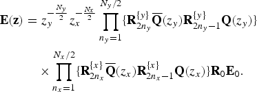 $$\eqalign{{\bf E}({\bf z}) &= z_{y}^{-{N_{y} \over 2}}z_{x}^{-{N_{x} \over 2}} \prod_{n_{y} = 1}^{{N_{y}}/2} \lcub {\bf R}_{2n_{y}}^{\{{y}\}} \overline{\bf Q}(z_{y}){\bf R}_{2n_{y}-1}^{\{{y}\}}{\bf Q}(z_{y})\rcub \cr &\quad\times \prod_{n_{x} = 1}^{{N_{x}}/{2}} \lcub {\bf R}_{2n_{x}}^{\{{x}\}}\overline{\bf Q}(z_{x}){\bf R}_{2n_{x} - 1}^{\{{x}\}} {\bf Q}(z_{x})\rcub {\bf R}_{0}{\bf E}_{0}.} $$
Figure 1(a) shows the lattice structure which corresponds to (5), where we omit to illustrate delays
![]() $z_{y}^{-{N_{y}}/{2}}$
and
$z_{y}^{-{N_{y}}/{2}}$
and
![]() $z_{x}^{-{N_{x}}/{2}}$
since they are less significant later. Note that the operation with Q(z
d
) is realized by the combination of the following matrices:
$z_{x}^{-{N_{x}}/{2}}$
since they are less significant later. Note that the operation with Q(z
d
) is realized by the combination of the following matrices:
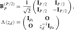 $$\eqalign{{\bf B}_{P}^{(P/2)} &= {1 \over \sqrt{2}} \left(\matrix{{\bf I}_{P/2} & {\bf I}_{P/2} \cr {\bf I}_{P/2} & -{\bf I}_{P/2}} \right),\cr {\bf \Lambda}(z_d) &= \left(\matrix{{\bf I}_{p_{s}} & {\bf O} \cr {\bf O} & z_{d}^{-1}{\bf I}_{p_{a}}} \right)}$$
as
![]() ${\bf Q}(z_{d}) = {\bf B}_{P}^{(P/2)}{\bf \Lambda}(z_{d}){\bf B}_{P}^{(P/2)}$
. Then, the operation with
${\bf Q}(z_{d}) = {\bf B}_{P}^{(P/2)}{\bf \Lambda}(z_{d}){\bf B}_{P}^{(P/2)}$
. Then, the operation with
![]() $\overline{\bf Q}(z_{d})$
is realized by
$\overline{\bf Q}(z_{d})$
is realized by
![]() ${\bf B}_{P}^{(P/2)}$
and
${\bf B}_{P}^{(P/2)}$
and
as
![]() $\overline{\bf Q}(z_{d}) = {\bf B}_{P}^{(P/2)}\overline{\bf \Lambda}(z_{d}){\bf B}_{P}^{(P/2)}$
.
$\overline{\bf Q}(z_{d}) = {\bf B}_{P}^{(P/2)}\overline{\bf \Lambda}(z_{d}){\bf B}_{P}^{(P/2)}$
.
2) Type-II NSOLT with p s >p a
Similarly, using the advance shifters, Type-II NSOLT is realized by
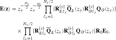
Then, we can rewrite (4) for even N y and N x as
 $$\eqalign{{\bf E}({\bf z}) &= z_{y}^{-{N_{y} \over 2}}z_{x}^{-{N_{x} \over 2}} \prod_{\ell_{y} = 1}^{N_{y}/2} \lcub {\bf R}_{E\ell_{y}}^{\{{y}\}} \overline{\bf Q}_{E}(z_{y}){\bf R}_{O\ell_{y}}^{\{{y}\}}{\bf Q}_{O}(z_{y})\rcub \cr &\quad \times \prod_{\ell_{x} = 1}^{N_{x}/2} \lcub {\bf R}_{E\ell_{x}}^{\{{x}\}} \overline{\bf Q}_{E}(z_{x}){\bf R}_{O\ell_{x}}^{\{{x}\}} {\bf Q}_{O}(z_{x})\rcub {\bf R}_{0}{\bf E}_{0}.} $$
Figure 1(b) illustrates the lattice structure for (6), where we omit to draw the delays
![]() $z_{y}^{-{N_{y}}/{2}}$
and
$z_{y}^{-{N_{y}}/{2}}$
and
![]() $z_{x}^{-{N_{x}}/{2}}$
. Here, note that Q
E
(z
d
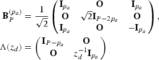
) is realized by the combination of the following matrices:
$z_{x}^{-{N_{x}}/{2}}$
. Here, note that Q
E
(z
d
) is realized by the combination of the following matrices:
 $$\eqalign{{\bf B}_{P}^{(p_{a})} &= {1 \over \sqrt{2}} \left(\matrix{{\bf I}_{p_{a}} &{\bf O} &{\bf I}_{p_{a}} \cr {\bf O} &\sqrt{2}{\bf I}_{P - 2p_{a}} &{\bf O} \cr {\bf I}_{p_{a}} &{\bf O} &-{\bf I}_{p_{a}}} \right),\cr {\bf \Lambda} (z_{d}) &= \left(\matrix{{\bf I}_{P - p_{a}} &{\bf O} \cr {\bf O} &z_{d}^{-1} {\bf I}_{p_{a}}} \right)}$$
as
![]() ${\bf Q}_{E}(z_{d}) = {\bf B}_{P}^{(p_{a})}{\bf \Lambda}(z_{d}){\bf B}_{P}^{(p_{a})}$
. In addition,
${\bf Q}_{E}(z_{d}) = {\bf B}_{P}^{(p_{a})}{\bf \Lambda}(z_{d}){\bf B}_{P}^{(p_{a})}$
. In addition,
![]() $\overline{\bf Q}_{E}(z_{d})$
is realized by
$\overline{\bf Q}_{E}(z_{d})$
is realized by
![]() ${\bf B}_{P}^{(p_{a})}$
and
${\bf B}_{P}^{(p_{a})}$
and
that is,
![]() $\overline{\bf Q}_{E}(z_{d}) = {1 \over 2} {\bf B}_{P}^{(p_{a})} \overline{\bf \Lambda} (z_{d}) {\bf B}_{P}^{(p_{a})}$
.
$\overline{\bf Q}_{E}(z_{d}) = {1 \over 2} {\bf B}_{P}^{(p_{a})} \overline{\bf \Lambda} (z_{d}) {\bf B}_{P}^{(p_{a})}$
.
III. BOUNDARY OPERATION
In this section, we illustrate blockwise implementation of NSOLT based on the lattice structure, and propose the boundary operation for AT. Note that we describe them for Type-II NSOLT mainly because the way of the primitive block operations and the boundary operation for Type-II NSOLT are different from the previous work in [Reference Muramatsu, Kobayashi, Hiki and Kikuchi19]. Thus, this is the main contribution of this work. In contrast, these operations for Type-I NSOLT are almost the same as [Reference Muramatsu, Kobayashi, Hiki and Kikuchi19] so that we omit to show the details of primitive block operations and the boundary operation for Type-I NSOLT.
A) Primitive block operations
1) Type-I NSOLT
The primitive block operation for Type-I NSOLT is realized using the operations in Fig. 2. These operations are detailed in next paragraph section. Note that the center block vanishes from the block operations for Type-I NSOLT.

Fig. 2. Primitive block operations for Type-II NSOLT, where the white and shaded regions mean operations for upper and lower half intermediate coefficient vectors, respectively, where I in the center block is the identity matrix for center intermediate coefficient. (a) E
0, (b) R
0, (c)
![]() ${\bf B}_{P}^{(p_{a})}$
, (d)
${\bf B}_{P}^{(p_{a})}$
, (d)
![]() ${\bf R}_{O\ell}^{\{d\}}$
, (e)
${\bf R}_{O\ell}^{\{d\}}$
, (e)
![]() ${\bf R}_{E\ell}^{\{d\}}$
, (f) Λ(z
x
), (g) Λ(z
y
), (h)
${\bf R}_{E\ell}^{\{d\}}$
, (f) Λ(z
x
), (g) Λ(z
y
), (h)
![]() $\overline{\bf \Lambda}(z_{x})$
, and (i)
$\overline{\bf \Lambda}(z_{x})$
, and (i)
![]() $\overline{\bf \Lambda}(z_{y})$
.
$\overline{\bf \Lambda}(z_{y})$
.
2) Type-II NSOLT with p s >p a
Figure 2 summarizes the primitive block operations required for analyzing an image based on the product form of (6), where 2×2 neighboring blocks are illustrated. Combination of these primitive operations can implement the analysis process, as in Fig. 1(b). Because the synthesis process is realized through the inverse primitive operations in reverse order, we omit to show the detail.
The first operation with delay chain d(z), downsampling by factor
![]() ${\bf M} ( = \hbox{diag} (M_{y}, M_{x}))$
, and the transform by matrix E
0 in Fig. 1 are exactly the same as the 2D block DCT, which is shown in Fig. 2(a). Note that operation (a) is adopted to the block before inserting the center block coefficient. After dividing the 2D DCT coefficients into two sets according to the atom symmetry, that is, even or odd symmetry, the transform with matrix R
0 is applied as in Fig. 2(b), where the white and shaded regions except the center block show operations for intermediate coefficients analyzed by the even- and odd-symmetric 2D DCT basis images.
${\bf M} ( = \hbox{diag} (M_{y}, M_{x}))$
, and the transform by matrix E
0 in Fig. 1 are exactly the same as the 2D block DCT, which is shown in Fig. 2(a). Note that operation (a) is adopted to the block before inserting the center block coefficient. After dividing the 2D DCT coefficients into two sets according to the atom symmetry, that is, even or odd symmetry, the transform with matrix R
0 is applied as in Fig. 2(b), where the white and shaded regions except the center block show operations for intermediate coefficients analyzed by the even- and odd-symmetric 2D DCT basis images.
Figures 2(c)–(i) relate to the support extension of atoms. Figure 2(c) shows the operation with
![]() ${\bf B}_{P}^{(p_{a})}$
. This is nothing but the butterfly calculation. Figure 2(d) illustrates the transform corresponds to matrix
${\bf B}_{P}^{(p_{a})}$
. This is nothing but the butterfly calculation. Figure 2(d) illustrates the transform corresponds to matrix
![]() ${\bf R}_{O\ell}^{\{d\}}$
that processes only the lower half intermediate coefficients through matrix
${\bf R}_{O\ell}^{\{d\}}$
that processes only the lower half intermediate coefficients through matrix
![]() ${\bf U}_{\ell}^{\{d\}}$
. In Fig. 2(e), the matrix
${\bf U}_{\ell}^{\{d\}}$
. In Fig. 2(e), the matrix
![]() ${\bf R}_{E\ell}^{\{d\}}$
is applied to the upper half intermediate coefficients including the center block through matrix
${\bf R}_{E\ell}^{\{d\}}$
is applied to the upper half intermediate coefficients including the center block through matrix
![]() ${\bf W}_{\ell}^{\{d\}}$
. Operations
${\bf W}_{\ell}^{\{d\}}$
. Operations
![]() ${\bf \Lambda}(z_{x})$
and
${\bf \Lambda}(z_{x})$
and
![]() ${\bf \Lambda}(z_{y})$
in Figs 2(f) and (g) delay the lower half intermediate coefficients.
${\bf \Lambda}(z_{y})$
in Figs 2(f) and (g) delay the lower half intermediate coefficients.
![]() ${\bf \Lambda}(z_{x})$
borrows the coefficients from the left block. Similarly,
${\bf \Lambda}(z_{x})$
borrows the coefficients from the left block. Similarly,
![]() ${\bf \Lambda}(z_{y})$
shifts the left block coefficients from the upper block. Figures 2(h) and (i) illustrate the operations of
${\bf \Lambda}(z_{y})$
shifts the left block coefficients from the upper block. Figures 2(h) and (i) illustrate the operations of
![]() $\overline{\bf \Lambda}(z_{x})$
and
$\overline{\bf \Lambda}(z_{x})$
and
![]() $\overline{\bf \Lambda}(z_{y})$
, which return the upper half coefficients to the left and upper blocks, respectively. These primitive block operations are applied to every block in the order indicated by (6).
$\overline{\bf \Lambda}(z_{y})$
, which return the upper half coefficients to the left and upper blocks, respectively. These primitive block operations are applied to every block in the order indicated by (6).
Note that all of the operations illustrated in Figs 2(a)–(e) are independent of the other blocks. Although the delay and advance shift operations shown in Figs 2(f)–(i) depend on the others, the relation is limited to the neighboring blocks. Therefore, the non-singular matrices W
0, U
0,
![]() ${\bf U}_{\ell}^{\{d\}}$
, and
${\bf U}_{\ell}^{\{d\}}$
, and
![]() ${\bf W}_{\ell}^{\{d\}}$
can vary block by block without any violation to the perfect reconstruction of the whole system.
${\bf W}_{\ell}^{\{d\}}$
can vary block by block without any violation to the perfect reconstruction of the whole system.
B) Boundary operation
The boundary treatment should be taken into account for some image analysis–synthesis systems since it can cause distortion at boundary for the image processing applications. Unfortunately, the popular symmetric extension approach is not available for NSOLT unless the fourfold symmetry is satisfied.
As a solution, we propose to terminate the dependence between neighboring blocks by shrinking the support region of atoms. In Type-I NSOLT, AT can be realized by locally making the support extension stages
![]() $\{{\bf R}_{2n_{d}}{\overline{\bf Q}}(z_{d}){\bf R}_{2n_{d}-1}^{\{d\}}{\bf Q}(z_{d})\}$
null order, i.e., independent of z
d
. This purpose is achieved if we can cancel the delay and advance shifters out locally and make the support extension invalid. In Type-II NSOLT, it can be realized by making
$\{{\bf R}_{2n_{d}}{\overline{\bf Q}}(z_{d}){\bf R}_{2n_{d}-1}^{\{d\}}{\bf Q}(z_{d})\}$
null order, i.e., independent of z
d
. This purpose is achieved if we can cancel the delay and advance shifters out locally and make the support extension invalid. In Type-II NSOLT, it can be realized by making
![]() $\{{\bf R_{E\ell}^{\{d\}}}{\overline{\bf Q}}_{E}(z_{d}){\bf R}_{O\ell}^{\{d\}}{\bf Q}_{O}(z_{d})\}$
null order local. Let us show how to realize the AT process in each type of NSOLT.
$\{{\bf R_{E\ell}^{\{d\}}}{\overline{\bf Q}}_{E}(z_{d}){\bf R}_{O\ell}^{\{d\}}{\bf Q}_{O}(z_{d})\}$
null order local. Let us show how to realize the AT process in each type of NSOLT.
1) Type-I NSOLT
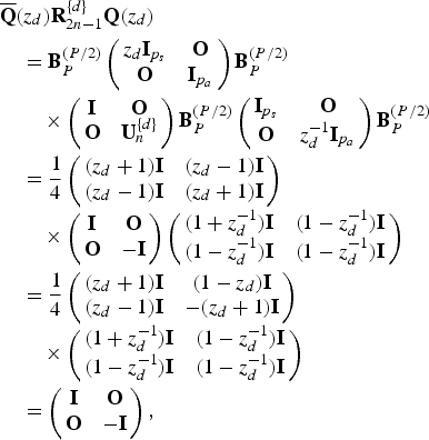
AT for Type-I NSOLT can be realized by locally setting
![]() ${\bf U}_{2n-1}^{\{d\}} = -{\bf I}$
as follows:
${\bf U}_{2n-1}^{\{d\}} = -{\bf I}$
as follows:
 $$\eqalign{&\overline{\bf Q}(z_{d}){\bf R}_{2n - 1}^{\{d\}} {\bf Q}(z_{d}) \cr &\quad = {\bf B}_{P}^{(P/2)} \left(\matrix{z_{d}{\bf I}_{p_{s}} &{\bf O} \cr {\bf O} & {\bf I}_{p_{a}}} \right) {\bf B}_{P}^{(P/2)} \cr &\qquad \times \left(\matrix{{\bf I} & {\bf O} \cr {\bf O} & {\bf U}_{n}^{\{d\}}} \right) {\bf B}_{P}^{(P/2)} \left(\matrix{{\bf I}_{p_{s}} & {\bf O} \cr {\bf O} & z_{d}^{-1}{\bf I}_{p_{a}}} \right) {\bf B}_{P}^{(P/2)} \cr &\quad = {1 \over 4} \left(\matrix{(z_{d} + 1) {\bf I} &(z_{d} - 1) {\bf I} \cr (z_{d} - 1) {\bf I} &(z_{d} + 1) {\bf I}} \right) \cr &\qquad \times \left(\matrix{{\bf I} &{\bf O} \cr {\bf O} &-{\bf I}} \right) \left(\matrix{(1 + z_{d}^{-1}){\bf I} &(1 - z_{d}^{-1}) {\bf I} \cr (1 - z_{d}^{-1}){\bf I} & (1 - z_{d}^{-1}) {\bf I}} \right) \cr &\quad = {1 \over 4} \left(\matrix{(z_{d} + 1){\bf I} &(1 - z_{d}){\bf I} \cr (z_{d} - 1){\bf I} &-(z_{d} + 1) {\bf I}} \right) \cr &\qquad \times \left(\matrix{(1 + z_{d}^{-1}){\bf I} & (1-z_{d}^{-1}){\bf I} \cr (1-z_{d}^{-1}){\bf I} & (1-z_{d}^{-1}){\bf I}} \right) \cr &\quad = \left(\matrix{{\bf I} & {\bf O} \cr {\bf O} & -{\bf I}} \right),} $$
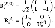
where
 $$\eqalign{{\bf B}_{P}^{(P/2)} &= {1 \over \sqrt{2}} \left(\matrix{{\bf I} &{\bf I} \cr {\bf I} &-{\bf I}} \right), \cr {\bf R}_{n}^{\{d\}} &= \left(\matrix{{\bf I}_{p_{s}} &{\bf O} \cr {\bf O} &{\bf U}_{n}^{\{d\}}} \right).}$$
Equation (7) shows that the Type-I NSOLT can cancel the overlapping property of atoms. If the horizontal parameter matrices
![]() ${\bf U}_{2n - 1}^{\{{x}\}}$
for all n in a block set to −I, the relation of the current block to the left block is terminated. In addition, the vertical parameter matrices
${\bf U}_{2n - 1}^{\{{x}\}}$
for all n in a block set to −I, the relation of the current block to the left block is terminated. In addition, the vertical parameter matrices
![]() ${\bf U}_{2n - 1}^{\{{y}\}}$
for all n in a block to −I terminates the relation of the current block to the upper block. This relation is equivalent to the BT in [Reference Muramatsu, Kobayashi, Hiki and Kikuchi19] because the number of upper and lower half intermediate coefficients are
${\bf U}_{2n - 1}^{\{{y}\}}$
for all n in a block to −I terminates the relation of the current block to the upper block. This relation is equivalent to the BT in [Reference Muramatsu, Kobayashi, Hiki and Kikuchi19] because the number of upper and lower half intermediate coefficients are
![]() $p_{s} = p_{a} = {P \over 2}$
. From this fact, for Type-I NSOLT, the AT procedure becomes almost the same as the BT procedure. Thus, we omit to show the detailed derivation of AT for Type-I NSOLT.
$p_{s} = p_{a} = {P \over 2}$
. From this fact, for Type-I NSOLT, the AT procedure becomes almost the same as the BT procedure. Thus, we omit to show the detailed derivation of AT for Type-I NSOLT.
AT for Type-II NSOLT is, however, different from the Type-I case. The difference appears in the implementation of Figs 4(c) and (g) for coefficient shift processes. In the case of Type-I NSOLT, these processes are applied to only upper and lower half intermediate coefficients except for the center block.
2) Type-II NSOLT
Type-II NSOLT AT can be realized by locally setting for
![]() ${\bf U}_{\ell}^{\{d\}}=-{\bf I}$
as follows:
${\bf U}_{\ell}^{\{d\}}=-{\bf I}$
as follows:
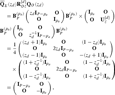 $$\eqalign{&\overline{\bf Q}_{E} (z_{d}){\bf R}_{O\ell}^{\{d\}}{\bf Q}_O(z_{d}) \cr &\quad ={\bf B}_{P}^{(p_{a})} \left(\matrix{z_{d}{\bf I}_{P-p_{a}} & {\bf O} \cr {\bf O} & {\bf I}_{p_{a}}} \right) {\bf B}_{P}^{(p_{a})} \times \left(\matrix{{\bf I}_{p_{a}} &{\bf O} \cr {\bf O} &{\bf U}_{\ell}^{\{d\}}} \right) \cr &{\bf B}_{P}^{(p_{a})} \left(\matrix{{\bf I}_{p_{a}} & {\bf O} \cr {\bf O} & z_{d}^{-1}{\bf I}_{P-p_{a}}} \right) {\bf B}_{P}^{(p_{a})} \cr &\quad = {1 \over 4} \left(\matrix{(z_{d} + 1) {\bf I}_{p_{a}} &{\bf O} &(1 - z_{d}){\bf I}_{p_{a}} \cr {\bf O} &2z_{d}{\bf I}_{P - p_{a}} &{\bf O} \cr (z_{d} - 1) {\bf I}_{p_{a}} &{\bf O} &-(z_{d} + 1){\bf I}_{p_{a}}} \right) \cr &\qquad \times \left(\matrix{(1 + z_{d}^{-1}){\bf I}_{p_{a}} &{\bf O} &(1 - z_{d}^{-1}){\bf I}_{p_{a}} \cr {\bf O} & 2z_{d}{\bf I}_{P - p_{a}} &{\bf O} \cr (1 - z_{d}^{-1}){\bf I}_{p_{a}} & {\bf O} & (1+z_{d}^{-1}){\bf I}_{p_{a}}} \right) \cr &\quad = \left(\matrix{{\bf I}_{P-p_{a}} & {\bf O} \cr {\bf O} & -{\bf I}_{p_{a}}} \right),} $$
where
 $$\eqalign{{\bf B}_{P}^{(p_{a})} &= {1 \over \sqrt{2}} \left(\matrix{{\bf I}_{p_{a}} & {\bf O} & {\bf I}_{p_{a}} \cr {\bf O} & \sqrt{2}{\bf I}_{P-2m} & {\bf O} \cr {\bf I}_{p_{a}} & {\bf O} & -{\bf I}_{p_{a}}} \right),\cr {\bf R}_{O\ell}^{\{d\}} &= \left(\matrix{{\bf I}_{p_{a}}& {\bf O} \cr {\bf O} & {\bf U}_{\ell}^{\{d\}}} \right).}$$
From (8), Type-II NSOLT can also control the overlapping property of atoms. It is noticed that the relation in (8) reduces the number of overlapping blocks in direction d∈{y, x}. If the horizontal parameter matrices
![]() ${\bf U}_{\ell}^{\{{x}\}} $
for all ℓ in a block set to −I, the relation of the current block to the left block is terminated. In addition, the vertical parameter matrices
${\bf U}_{\ell}^{\{{x}\}} $
for all ℓ in a block set to −I, the relation of the current block to the left block is terminated. In addition, the vertical parameter matrices
![]() ${\bf U}_{\ell}^{\{{y}\}}$
for all ℓ in a block to −I terminates the relation of the current block to the upper block.
${\bf U}_{\ell}^{\{{y}\}}$
for all ℓ in a block to −I terminates the relation of the current block to the upper block.
Figure 3 illustrates the termination block position, where the blocks including ‘|’, ‘−’ and ‘+’ denote the termination blocks in the horizontal, vertical, and both directions. Around the original picture, any value can be assumed since they have no influence on the essential transform coefficients.

Fig. 3. Boundary operation with AT, where the shaded area denotes the original support region of a given image. The blocks including ‘|’, ‘−’ and ‘+’ denote termination blocks in the horizontal, vertical, and both directions, respectively.
Figure 4 illustrates the local AT procedure in the blockwise operation for Type-II NSOLT, where succeeding three blocks are denoted. Note that the discussion holds for both the horizontal and vertical directions. In Fig. 4(a), u
b
and v
b
denote upper and lower intermediate coefficients, where b means the relative position from the current block. As well, the c
b
in the center block contains a part of upper half intermediate coefficients vector. The next step is the butterfly operation with
![]() ${\bf B}_{P}^{(p_{a})}$
for u
b
and v
b
block by block in Fig. 4(b), where
${\bf B}_{P}^{(p_{a})}$
for u
b
and v
b
block by block in Fig. 4(b), where
![]() ${\bf w}_{b} = {\bf u}_{b} + {\bf v}_{b}$
and
${\bf w}_{b} = {\bf u}_{b} + {\bf v}_{b}$
and
![]() ${\bf x}_{b} = {\bf u}_{b} - {\bf v}_{b}$
. The butterfly operations are not adopted to c
b
. Then, each lower vector x
b
and the center block c
b
are moved to next block as shown in Fig. 4(c). After the operation Fig. 4(c), the butterfly operation is applied to vectors u
b
and v
b
again as in Fig. 4(d). In Fig. 4(e), the transform with
${\bf x}_{b} = {\bf u}_{b} - {\bf v}_{b}$
. The butterfly operations are not adopted to c
b
. Then, each lower vector x
b
and the center block c
b
are moved to next block as shown in Fig. 4(c). After the operation Fig. 4(c), the butterfly operation is applied to vectors u
b
and v
b
again as in Fig. 4(d). In Fig. 4(e), the transform with
![]() ${\bf U}_{\ell}^{\{d\}}$
is applied to each lower vector, where we set
${\bf U}_{\ell}^{\{d\}}$
is applied to each lower vector, where we set
![]() ${\bf U}_{\ell}^{\{d\}} = -{\bf I}$
for the block of interest in the thick frame. After the butterfly operation in Fig. 4(f), each upper vector is advanced to the previous block, as shown in Fig. 4(g), and the butterfly operation is applied to as in Fig 4(h).
${\bf U}_{\ell}^{\{d\}} = -{\bf I}$
for the block of interest in the thick frame. After the butterfly operation in Fig. 4(f), each upper vector is advanced to the previous block, as shown in Fig. 4(g), and the butterfly operation is applied to as in Fig 4(h).

Fig. 4. AT flow of the blockwise operations corresponding to (8), where succeeding three blocks are exemplified. (a) Intermediate coefficients of each blocks. (b) Operation with B
P
(m). (c) Operation with Λ(z
x
). (d) Operation with B
P
(m). (e) Operation with
![]() ${\bf R}_{O\ell}^{\{d\}}$
. (f) Operation with B
P
(m). (g) Operation with
${\bf R}_{O\ell}^{\{d\}}$
. (f) Operation with B
P
(m). (g) Operation with
![]() $ \overline{{\bf \Lambda}}(z_{x})$
. (h) Operation with B
P
(m). These operations from (a) to (h) are applied alphabetical order, where
$ \overline{{\bf \Lambda}}(z_{x})$
. (h) Operation with B
P
(m). These operations from (a) to (h) are applied alphabetical order, where
![]() ${\bf U} = {\bf U}_{\ell}^{\{d\}}$
. In (e), the thick frame shows that the block to which parameter
${\bf U} = {\bf U}_{\ell}^{\{d\}}$
. In (e), the thick frame shows that the block to which parameter
![]() ${\bf U}_{\ell}^{\{d\}} = -{\bf I}$
is applied. The vertical dashed line in (g) and (h) denotes the separation of dependence between the blocks. For convenience, we omit to show the details in the right block in (h). Note that c
b
in center block is operation of inserting zero in Fig. 1.
${\bf U}_{\ell}^{\{d\}} = -{\bf I}$
is applied. The vertical dashed line in (g) and (h) denotes the separation of dependence between the blocks. For convenience, we omit to show the details in the right block in (h). Note that c
b
in center block is operation of inserting zero in Fig. 1.
Note that the left block of the vertical dashed line in Fig. 4(h) is independent of the coefficients for b≥0. Similarly, the right block is independent of the coefficients for b<0. These facts imply that these blocks have no relation to each other. That is, the atoms are terminated at the vertical dashed line without any violation to the perfect reconstruction.
IV. EXPERIMENTAL RESULT
Let us verify the significance of the proposed AT technique. Different from [Reference Furuya, Hara and Muramatsu21], the IHT algorithm was adopted in this experiment. In this experiment, we use filters of three different extent, where polyphase order (N y , N x ) are set to (2, 2), (4, 4) and (6, 6). Figure 5 shows an example set of impulse responses and frequency amplitude responses designed using the method in [Reference Muramatsu and Aizawa12]. Figure 6 shows original images in this experiment. We apply each image to NSOLT with PE and AT. Parameter setting of NSOLT is shown in Table 1. Figure 7 shows eight examples of the terminated atom sets and one normal atom set. It is observed that the region of support is properly controlled through the local termination process. These atoms are no longer symmetric at the border. However, they keep the PR property and prevent the wrapping effect caused by the PE method.

Fig. 5. Design example of Type-II NSOLT, where the impulse responses are shown in the top, and frequency amplitude responses are shown in the bottom, where P=p a +p s =7, M y =M x =2 (M=4), and N y =N x =4.

Fig. 6. Original images of size 128×128, 8-bit grayscale. (a) lena, (b) goldhill, (c) barbara, and (d) baboon.

Fig. 7. Examples of terminated atom sets and the original normal atom set, where the contrast of each atom is enhanced in order to clarify the region of support. (a) Top left. (b) Top. (c) Top right. (d) Left. (e) Normal. (f) Right. (g) Bottom left. (h) Bottom. (i) Bottom right.
Table 1. Experimental settings of IHT with NSOLT.

Figure 8 shows a part of experimental results of IHT with NSOLT of polyphase
![]() $(N_{y}, N_{x}) = (4, 4)$
. The original picture is given in Figs 8(a)–(c) show the reconstruction results of PE and AT, respectively. From Fig. 8, it is observed that the PE method occurs wrapping effect at the right and bottom boundary, while the AT method, does not. Table 2 shows peak signal-to-noise ratio (PSNR) for NSOLT of different polyphase order. From Table 2, NSOLT with AT gives a higher PSNR than that with PE in each case.
$(N_{y}, N_{x}) = (4, 4)$
. The original picture is given in Figs 8(a)–(c) show the reconstruction results of PE and AT, respectively. From Fig. 8, it is observed that the PE method occurs wrapping effect at the right and bottom boundary, while the AT method, does not. Table 2 shows peak signal-to-noise ratio (PSNR) for NSOLT of different polyphase order. From Table 2, NSOLT with AT gives a higher PSNR than that with PE in each case.

Fig. 8. A part of experimental result with IHT in the case of (N y , N x )=(4, 4). (a) Original. (b) NSOLT with PE (PSNR: 26.80 [dB]). (c) NSOLT with AT (PSNR: 28.12 (dB)). In this experiment, six-level hierarchical 2D wavelet construction was adopted and the number of transform coefficients in IHT was set to 500.
Table 2. Experimental result of PSNR (dB) with PE and AT.

V. CONCLUSION
In this work, we proposed a blockwise implementation of 2D NSOLTs and a boundary operation technique. This technique was shown to serve local variability of atoms without any violation of the perfect reconstruction. The blockwise implementation is effective for the image processing application since it allows us to control the region of support locally and leads an AT to prevent distortion at image boundary. Through experiments with IHT, we verified the significance of the proposed AT.
ACKNOWLEDGEMENT
This work was supported by KAKENHI (Grant no. 26420347).
Kosuke Furuya received his B.E. degree in Electrical and Electronic Engineering from Niigata University, Japan, in 2013. He received the M.E. degree in Electrical and Information Engineering from Graduate School of Niigata University and he joined Toyota Motor Corp. in 2015. His research interests include image processing.
Shintaro Hara received the B.E. degree in Electrical and Electronic Engineering from Niigata University in 2012. He received the M.E. degree in Electrical and Information Engineering from Graduate School of Science and Technology, Niigata University, and he joined Canon Imaging Systems Inc. in 2014.
Kenta Seino received B.E. degree in Electrical and Electronic Engineering from Niigata University in 2014. He is currently registered at graduate school of Niigata University. His research interests are in image processing. He received the Electrical Academic Incentive Award from the Institute of Electrical Engineers of Japan in 2014.
Shogo Muramatsu received B.E., M.E., and Ph.D. degrees from Tokyo Metropolitan University in 1993, 1995, and 1998, respectively. From 1997 to 1999, he worked at Tokyo Metropolitan University. In 1999, he joined{} Niigata University, where he is currently an Associate Professor in the Department of Electrical and Electronics Engineering, Faculty of Engineering. During year from 2003 to 2004, he was a visiting researcher at the University of Florence, Italy. His research interests are in multidimensional signal processing, multirate systems, image processing, video analysis, and embedded vision systems. Dr. Muramatsu is a senior member of IEEE (The Institute of Electrical and Electronics Engineers, Inc.) and IEICE (Institute of Electronics, Information and Communication Engineers of Japan), and a member of ITE (Institute of Image Information and Television Engineers of Japan).
