1 Introduction
Orthoses, prostheses, and exoskeletons (OPE) are biomedical devices that aid people with disabilities by stabilizing or immobilizing joints or by facilitating or supporting their locomotion. Orthoses modify structural characteristics of the musculoskeletal system, whereas prostheses replace missing body parts (Shurr, Michael & Cook Reference Shurr, Michael and Cook2002). Powered exoskeletons provide independent walking for mobility-impaired individuals, such as those suffering from spinal cord injury (Esquenazi, Talaty & Jayaraman Reference Esquenazi, Talaty and Jayaraman2017).
Mobility-aiding biomedical devices must fulfill many requirements including individualization for a specific patient in order to increase wearing comfort and improve locomotion. Regarding structural requirements, load-bearing components need to provide high stiffness and strength at low weight. To make biomedical structures economically viable, engineering effort and production costs for each personalized device must be minimized. Further requirements include aspects of bio-mechanics, mechatronics, and controls (Schrade et al. Reference Schrade, Dätwyler, Stücheli, Studer, Türk, Meboldt and Lambercy2018).
To meet the requirements of individualization, mechanical integrity, and cost efficiency, recent approaches make use of various rather novel technologies. These include 3D scanning to capture the shape and dimensions of body parts. Compared to manual techniques such as plaster-molding, labor effort and lead times are reduced. To fabricate customized OPE devices, many studies utilize the possibilities of additive manufacturing (AM), which is also known as 3D printing. Using 3D scanning and AM in combination with a digitized process chain allows to minimize the design effort to customize an OPE device to each individual patient. For example, for foot prostheses, the geometry of limbs is captured through 3D scanning, the data is converted into surface geometry, and the component is designed with a CAD software and then directly produced with AM (Jin et al. Reference Jin, Plott, Chen, Wensman and Shih2015). In the case of custom foot orthoses, devices can be fabricated with improved comfort and more evenly distributed pressure zones (Salles & Gyi Reference Salles and Gyi2013a ,Reference Salles and Gyi b ), while manufacturing costs are comparable to traditional methods (Saleh & Dalgarno Reference Saleh and Dalgarno2009).
Even though AM has made individualized biomedical devices more accessible, polymeric parts fabricated by AM lack durability and strength. To create stronger components, fiber reinforced polymers (FRP) can be employed as high-performance materials with excellent durability and stiffness- and strength-to-weight ratios. Combining FRP materials with the possibilities of AM offers a number of opportunities for the design and manufacturing of individualized, high-performance lightweight structures. These have been examined, e.g., in the context of layup tooling (Love et al. Reference Love, Kunc, Rios, Duty, Elliott, Post and Blue2014; Li et al. Reference Li, Taylor, Bheemreddy, Iyibilgin, Leu and Chandrashekhara2015; Schniepp Reference Schniepp2016) or lightweight applications with added functionalities such as AM honeycombs (Riss, Schilp & Reinhart Reference Riss, Schilp and Reinhart2014) or load introduction elements (LIE) (Türk, Klahn & Meboldt Reference Türk, Klahn and Meboldt2015). Studies that combine AM with FRP for OPE devices such as knee prostheses exist, but they focus mainly on the manufacturing route (Türk et al. Reference Türk, Einarsson, Lecomte and Meboldt2018b ).
In order to leverage the full lightweight potential of AM–FRP structures, it is desirable to optimize the layup of the composite face sheets and employ load-tailored laminates. The so-called fiber patch placement (FPP) approach offers a way to do so by assembling a structure from discrete fiber patches (Meyer Reference Meyer2008; Klein, Malezki & Wartzack Reference Klein, Malezki and Wartzack2015). Patches allow for local variation of the laminate throughout the structure, which thus has the potential of superior mechanical properties compared to conventional constant stiffness designs. Recent research presents a mechanical model for the analysis of patched laminates (Kussmaul, Zogg & Ermanni Reference Kussmaul, Zogg and Ermanni2018) as well as a framework for the automated optimization of individualized fiber patch reinforcements (Kussmaul et al. Reference Kussmaul, Jónasson, Zogg and Ermanni2019).
The literature review shows that for the creation of OPE devices, prior studies focused on selected technologies such as 3D scanning, a digitized process chain, fabrication with AM, and optimized FRP structures with tailored fiber patches. However, the combination of all of these technologies into an integrated design and manufacturing process for individualized and structurally optimized OPE applications is yet to be demonstrated. The combination of AM with FPP allows for the geometrical and structural individualization of biomedical structures, which thus are expected to show to date unrivaled performance. In this regard, the question arises as to what reasonable approach or strategy can be employed to effectively combine the technologies AM and FPP in order to (a) leverage the strengths of their combination and (b) make the complexity of the technologies and the effort in the design and manufacturing process manageable. This complexity is due to the multi-leveled, interdisciplinary design process, requiring expert knowledge in virtually every step. This expert know-how needs to be cast into appropriate tools or methods in order to realize individualized OPEs with a justifiable effort.
This study addresses the research question by introducing a design and manufacturing strategy for individualized, lightweight OPE structures and by presenting a digitized end-to-end design process chain. The corresponding concepts are illustrated for a lightweight component of an exoskeleton. To answer the research question, the paper is structured as follows: Section 2 provides background information on the employed fabrication methods and the examined reference application. Section 3 presents the proposed design and manufacturing strategy, whereas Section 4 outlines the utilized design process chain. The described concepts are demonstrated in Section 5. After discussing the results in Section 6, Section 7 concludes the article.
2 Background information
2.1 Technology: materials and processes
The design and manufacturing approach introduced herein makes use of fused deposition modeling (FDM) as the AM method of choice, as well as on advanced composites.
In FDM, a filament is fed through a heating element and extruded through a nozzle onto the building platform (Bellini & Güeri Reference Bellini and Güeri2003). Acrylonitrile butadiene styrene (ABS), polylactide, and polycarbonate are common materials for FDM. It requires support structures for overhangs, which are mechanically removed or chemically dissolved after manufacturing. Material properties are anisotropic as a result of process factors including directional deposition of the filament, air gap, bead width, and build temperature (Ahn et al. Reference Ahn, Montero, Odell, Roundy and Wright2002).
Composite materials are formed by the combination of at least two constituent materials with different properties to form a fully new material (Mazumdar Reference Mazumdar2001). Carbon fiber reinforced polymers (CFRP) consist of aligned carbon fiber reinforcements that are embedded in a polymeric resin (e.g. epoxy). For many high-performance applications, pre-impregnated (prepreg) fibers are used. These advanced composites are semi-finished products, in which the resin is kept in a pre-polymerized state through cooling. The autoclave prepreg process is the state-of-the-art manufacturing technique for high-performance applications. In this process, fiber prepregs are cut and laid down with the desired fiber orientation on a tool. The layup is vacuum-bagged and put in an autoclave, where defined temperatures ranging up to
![]() $180\,^{\circ }\text{C}$
and pressures up to 10 bar are applied for curing and consolidation of the part.
$180\,^{\circ }\text{C}$
and pressures up to 10 bar are applied for curing and consolidation of the part.
2.2 Application: reference component
The reference component of choice is the hip structure of VariLeg 2, a lower limb exoskeleton. The VariLeg 2 platform is detailed in a previous paper by Schrade et al. (Reference Schrade, Dätwyler, Stücheli, Studer, Türk, Meboldt and Lambercy2018). These exoskeletons generally serve two purposes, either as rehabilitation tools for use in clinics or as a personal mobility solution for mobility-impaired individuals (Aach et al. Reference Aach, Cruciger, Sczesny-Kaiser, Höffken, Meindl, Tegenthoff and Schildhauer2014). However, at present, the available exoskeletons have low real-life environment performance primarily due to their slow walking speeds (Louie, Eng & Lam Reference Louie, Eng and Lam2014) and also because of their limited capabilities to traverse uneven terrain. A way to achieve greater capability is to improve the mechanical structure of these devices, where, apart from the costs, weight, stiffness, strength, and individualization are key factors.
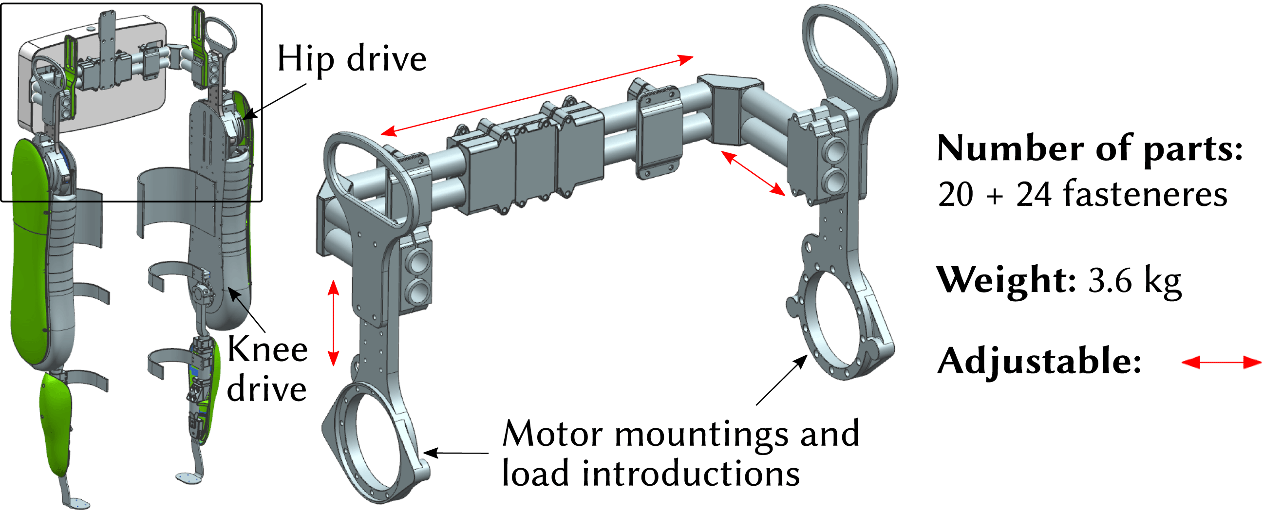
Figure 1. VariLeg 2 and aluminum reference hip component.
In this study, an integral component of the exoskeleton system, the hip component, is investigated. It is shown in Figure 1 and has several roles: it connects the two motorized legs of the exoskeleton, provides the torso attachment for the patient, and enables the mounting for the battery and electronics. The aluminum reference hip structure is assembled from aluminum profiles, which are connected by multiple clamping screws. Thus, it is able to fit different patients. However, the approach of having adjustability, as opposed to having an individualized structure, compromises its mechanical performance. For example, a statistical 95th percentile male patient poses a much greater design load than a 5th percentile female (Fryar et al. Reference Fryar, Gu, Ogden and Flegal2016). This means that for a significant proportion of patients, an adjustable design will be developed for an excessive load. It is thus too heavy, requiring stronger and heavier motors, and leading to a reduced agility and user-friendliness. In addition, an adjustable design consists of a multitude of single parts, resulting in a high number of interfaces in the structure. These interfaces, especially the friction-lock clamps, lead to a significant loss of stiffness, which is compromising locomotion precision.
To achieve a truly high-performance biomedical system, it is therefore desirable to aim toward an individualized structure. Such a structure is developed within the course of this paper. It relies on two basic building blocks: a design-assisted manufacturing approach and a digitized end-to-end design process chain.
3 Design-assisted manufacturing approach
3.1 Basic approach
The challenge of creating individualized, high-performance biomedical OPE structures is tackled by following a design-assisted manufacturing approach. The basic idea is to design an OPE structure in such a way that it combines the strengths and design opportunities of different technologies such as FRP, AM, and conventional technologies like milling. Especially, AM allows for the support and simplification of the manufacturing of multi-material structures by a purposeful utilization of its design freedom. Design and manufacturing development can thus be closely interlinked.
For the creation of a redesigned and optimized version of the reference exoskeleton hip structure, the following design principles are applied:
(i) use of an integral, multi-material-based design that combines the strengths of different materials and processes;
(ii) individualized design of a part using a digital design chain instead of a hardware-based adaption of a differential design;
(iii) application of CFRP in areas that require high strength and stiffness at low weight, e.g. for load-bearing shells that transfer loads over large distances;
(iv) use of AM processes for complex and patient-individual regions, e.g. shape-giving elements such as cores or molds for the layup of FRP material and for regions with added functionalities such as inserts or form fit joints for positioning of components;
(v) utilization of high-precision manufacturing technologies such as milling for metallic parts that transfer loads and require a high degree of geometric accuracy, e.g. at interfaces to other parts.
The following sections illustrate the design principles by presenting the redesign of the hip component together with the developed manufacturing route.
3.2 Design concept
The newly developed design concept is shown in Figure 2 and consists of three major components. These are milled LIE out of aluminum, a hollow CFRP shell, and an ABS core made by FDM, which serves as the shape-giving tool for the fabrication of the CFRP shell. Figure 2(a) illustrates the design concept for the FDM core, whereas Figure 2(b) depicts the final AM–CFRP hip component.
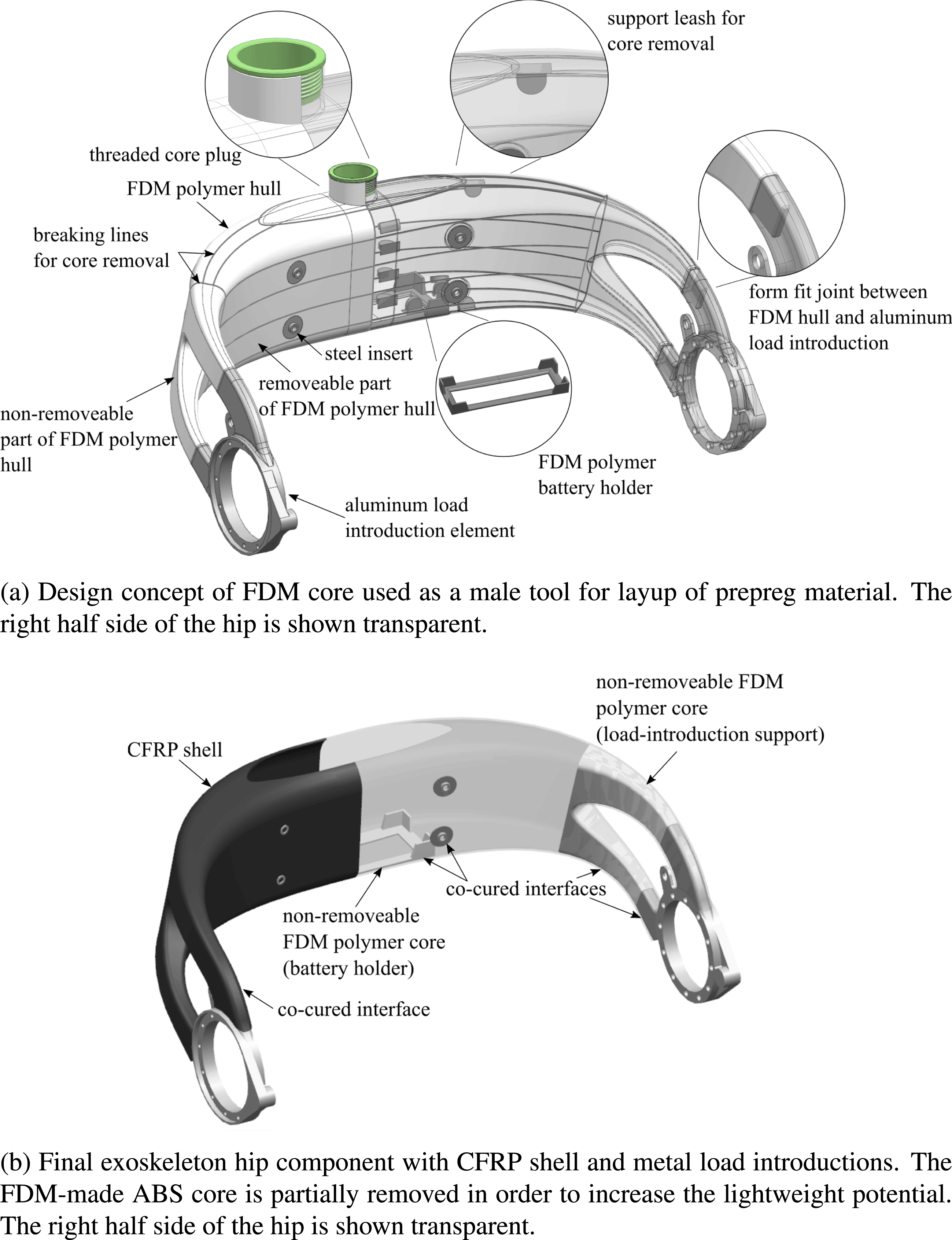
Figure 2. Exoskeleton hip design concept.
A thin-walled additively manufactured hollow core from ABS is the key element for realizing the patient-individual geometry of the hip structure. While ABS does not serve as an efficient lightweight material, the core can nevertheless be used as a male tooling element to be covered with load-carrying CFRP prepreg material. With the core being directly produced from digital patient data, it allows for the fast and cost-efficient production of lot-size one lamination tools. Moreover, in a pre-assembly step, the AM core serves as a positioning device for LIE via form fit joints, before the CFRP material is cured and consolidated. However, as the AM core is thin-walled, it would not withstand autoclave processing, which is carried out at elevated temperatures and pressures, without additional support. Hence, the core is filled with a granular filling material through an opening on its top prior to processing (Türk et al. Reference Türk, Ebnoether, Zogg and Meboldt2018a ). Next, the opening in the core is closed with a threaded plug as seen in Figure 2(a). Due to the thread, the filling material can be compressed by the plug, which ensures complete filling and minimizes the risk of core deformation during autoclave processing.
The CFRP shell is created by over-laminating the AM core. The exoskeleton hip is mainly subjected to bending and torsional loads. The basic mechanical concept is thus to carry out the main load-carrying part of the hip as a hollow, closed shell structure from CFRP. The shell features thin walls and a large enclosed cross-sectional area. In conjunction with its double-curved shape, it yields a high geometrical stiffness and a favorable membrane-dominated stress state in the structure. As seen in Figure 2(b), the CFRP shell has an opening on its top side, which allows the integration of batteries and electronics inside the exoskeleton hip structure.
Finally, the hip structure features LIE, which connect the CFRP shell to the motorized legs of the exoskeleton. As the interface to the motors is identical for each pilot, the LIEs are defined as standard parts and milled from aluminum. Milling ensures a high geometrical accuracy of the functional surfaces and allows to fabricate the parts in a cost-efficient manner.
The interfaces between CFRP and the ABS core as well as the interface between CFRP and the metal LIEs are created in a co-curing approach, where bonding of parts is formed in the autoclave process using the excessive resin of the prepreg material. Due to elevated temperature in the autoclave, attention has to be paid to residual stresses in the interfaces due to the mismatch of the coefficients of thermal expansion
![]() $\unicode[STIX]{x1D6FC}$
of the different materials. This
$\unicode[STIX]{x1D6FC}$
of the different materials. This
![]() $\unicode[STIX]{x1D6E5}\unicode[STIX]{x1D6FC}$
-problem is treated in detail in a separate publication (Pappas & Botsis Reference Pappas and Botsis2019).
$\unicode[STIX]{x1D6E5}\unicode[STIX]{x1D6FC}$
-problem is treated in detail in a separate publication (Pappas & Botsis Reference Pappas and Botsis2019).
Due to its weak ABS material, the FDM-made core of the hip component does hardly contribute to its load-carrying abilities. Hence, it compromises the lightweight potential of the final structure. For this reason, the core is designed to be removable from the inside of the CFRP shell after autoclave processing. To achieve this, the core is covered with release foil before prepreg layup. Moreover, in order to ease core removal, it is designed to be separable into smaller parts by the integration of rated breaking lines as seen in Figure 2(a). These rated breaking lines have a significantly smaller thickness than the rest of the core structure. That way, it can be dissected into smaller surfaces by applying mild force. To aid dissection, support leashes are designed on the inside of the AM core surface. These support leashes can be accessed via the opening on the top side of the hip structure. They allow generating the required mechanical force to rupture the core along the breaking lines. After the core is divided into small pieces, it can be removed through the top hole.
By removing the core, the lightweight potential of the final part is increased. However, the core is not completely removed. Those parts of the core which serve certain functions are left inside the CFRP shell. That is the case in the regions of the load introductions, where additional material support is reasonable. Moreover, one part of the core is used as a battery holder inside the CFRP shell. This battery holder is created by removing its surrounding ABS material with the help of the breaking lines as illustrated in Figure 2(a) and (b).
3.3 Manufacturing route
The employed manufacturing technique is a co-curing autoclave process. Its three major steps are illustrated in Figure 3.

Figure 3. Manufacturing process steps.
The core of the exoskeleton hip is made from ABS in an FDM process using a Stratasys Dimension Elite printer. In order to enable partial removal of the core, the respective core segments are then covered with release foil. Thereafter, the core is filled with common salt (NaCl) and closed with the threaded plug. Flexible outer tooling molds are made from thermoplastic polyurethane (TPU) in a selective laser sintering (SLS) process. These outer molds are used in areas of high geometrical complexity to increase the accuracy of the final part. The TPU molds are treated with release agent. The LIE are milled from aluminum AlZn5.5Mg1. In order to increase interface strength, their bonding surfaces are sandblasted.
The single components are pre-assembled and positioned using form fit joints designed in the ABS core. The pre-assembly is fixed on a jig to ensure exact positioning of the LIEs. The CFRP prepreg layers are laminated onto the assembly. The assembly is covered with the TPU molds, perforated release film, breather fabric, and finally vacuum-bagged. Curing is carried out in an autoclave at
![]() $80\,^{\circ }\text{C}$
and 3 bar pressure for 15 h.
$80\,^{\circ }\text{C}$
and 3 bar pressure for 15 h.
After curing, the part is demolded, the core is opened, and the salt filling is washed out. Through the top opening in the CFRP shell, the ABS core is dissected along its rated breaking lines and removed where intended. Finally, surface finishing is conducted.
4 Digitized end-to-end design process chain
The realization of individualized, high-performance lightweight structures requires the design of custom-made geometries and the adaptation of load-bearing components toward patient-individual load cases and design targets. To reduce time and costs for the individualization process, it is necessary to automate repetitive and routine design tasks as well as to preserve and reuse the design knowledge. The recurring tasks are:
(i) patient geometry acquisition and post-processing of scan data;
(ii) patient’s joints position determination;
(iii) adaption of the individualized component CAD model to each patient;
(iv) determination of patient-individual load cases;
(v) patient-individual structural analysis and optimization;
(vi) design of 3D-printable parts/molds.

Figure 4. Process chain for geometric and load-bearing individualization.
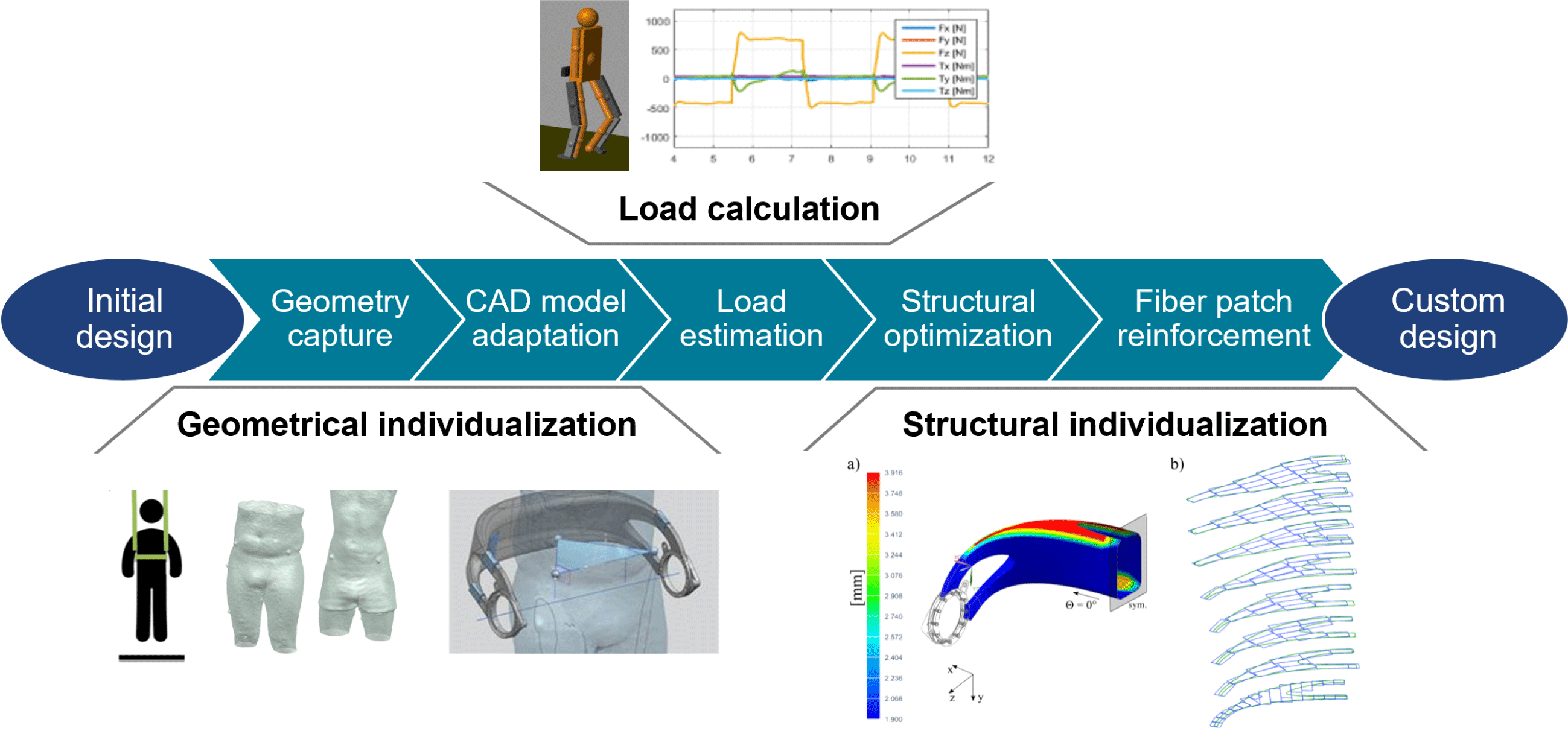
The following sections introduce a digital end-to-end design process chain, which is shown in Figure 4. It is explained in the context of the redesigned hip component but can also be adapted for other devices that benefit from customization such as various biomedical and sports products or robotic structures. After applying geometric individualization, the digital design chain carries out the individualization of the load-bearing composite structure.
4.1 Geometric individualization
Geometrical individualization aims at adapting the design of the hip component to the body shape of a patient to increase wearing comfort and to align the component with respect to the patient’s anatomy. The described process can be categorized as a standardized (or pre-planned) individualization (Spallek & Krause Reference Spallek and Krause2016). It is shown in Figure 5 and consists of two main steps, namely the acquisition of the patient data and the adaption of the geometric model.
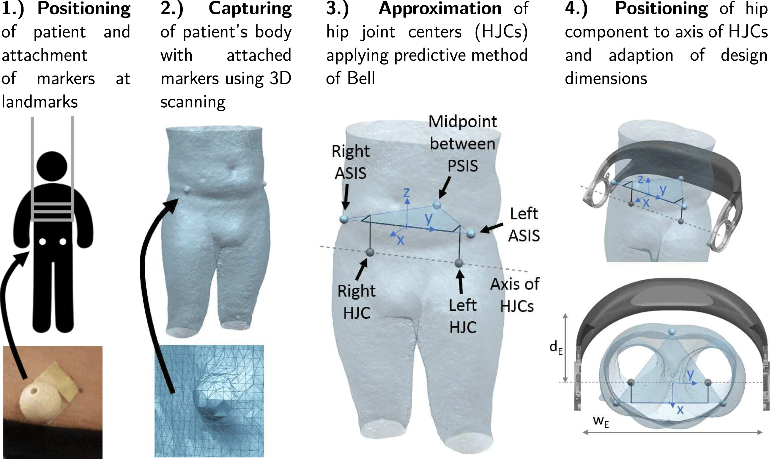
Figure 5. Process steps for geometric individualization.
Individualization of the hip component requires capturing of the geometry of the patient’s body. In addition, the position of the left and right hip joint center (HJC) must be determined in order to correctly align the axes of the hip drive motors, which are mounted on the LIE, with the rotation axis of the hip in a flexion or extension movement of the leg.
Geometry acquisition methods include clinical imaging techniques such as computer tomography (CT) and magnetic resonance imaging (MRI). Although CT and MRI allow capturing the body shape together with information on the body anatomy, they have a number of disadvantages. The required systems are usually only available in a clinic setting, very expensive, and may expose the patient to harmful radiation (Kainz et al.
Reference Kainz, Carty, Modenese, Boyd and Lloyd2015). 3D scanning offers a cost-efficient and easily accessible alternative. Scanners are available in various grades and precisions and allow capturing body shapes in a fast and easy process. For this research, a Microsoft Kinect V1 is used with a measurement uncertainty in the range of
![]() ${\sim}2$
–4 mm (Guidi, Gonizzi & Micoli Reference Guidi, Gonizzi and Micoli2016).
${\sim}2$
–4 mm (Guidi, Gonizzi & Micoli Reference Guidi, Gonizzi and Micoli2016).
To locate the positions of the HJCs, a predictive method is employed, which uses external anatomical landmarks of the hip pelvis (Lo, Chiou & Chou Reference Lo, Chiou and Chou2015). The landmarks are indicated in Figure 5. These are the left and right anterior superior iliac spines (ASIS) and the midpoint between the two posterior superior iliac spines (PSIS) located on the back side of the hip at the sacrum. The three points define a coordinate system with the midpoint of the ASIS as its center. The predictive method of Bell is based on regression equations and the data analyzed from CT scans of adult populations (Bell, Brand & Pedersen Reference Bell, Brand and Pedersen1989). It estimates the location of the HJCs with an error in the range of 10–25 mm (Kainz et al. Reference Kainz, Carty, Modenese, Boyd and Lloyd2015).
As illustrated in Figure 5, paraplegic patients are scanned in an upright position applying a lifting vest. Before 3D scanning, non-reflective balls with a diameter of 20 mm are attached to the anatomical landmarks on the patient’s body. Thereby, the body shape can be digitized together with the anatomical information on the HJCs within a single fast and easy procedure. After importing the 3D scan in a CAD program, the scanned markers are identified and Bell’s method is employed to locate the HJCs. The coordinate system given by the landmarks allows to position and orient the exoskeleton hip model.
The basis for the geometric individualization is a parametric CAD model, which is defined by a set of main design parameters, e.g. width
![]() $w_{E}$
and depth
$w_{E}$
and depth
![]() $d_{E}$
of the hip. These parameters can either be adjusted manually or are automatically set by intersecting the mesh of the 3D scan with vectors and lines that are predefined in the coordinate system. A change of the main design parameters leads to an update of higher level design features such as the composite shell or the AM core. The milled aluminum load introductions are standard parts and thus are not altered. The employed CAD model is defined as a surface-based representation and can thus be used in a convenient way for further processing steps such as simulation, optimization, and manufacturing.
$d_{E}$
of the hip. These parameters can either be adjusted manually or are automatically set by intersecting the mesh of the 3D scan with vectors and lines that are predefined in the coordinate system. A change of the main design parameters leads to an update of higher level design features such as the composite shell or the AM core. The milled aluminum load introductions are standard parts and thus are not altered. The employed CAD model is defined as a surface-based representation and can thus be used in a convenient way for further processing steps such as simulation, optimization, and manufacturing.
4.2 Load-bearing structure individualization
Individualization of the load-bearing structure is crucial for designing lightweight biomedical structures. It can be achieved by utilization of the so-called FPP method. The approach for obtaining a patient-specific set of optimal fiber patch reinforcements is illustrated in Figure 6. In order to load-tailor individualized components, at first, a load estimation model, providing individualized load cases, is run. In a second step, a structural optimization algorithm is carried out, which places patch reinforcements on the structure.
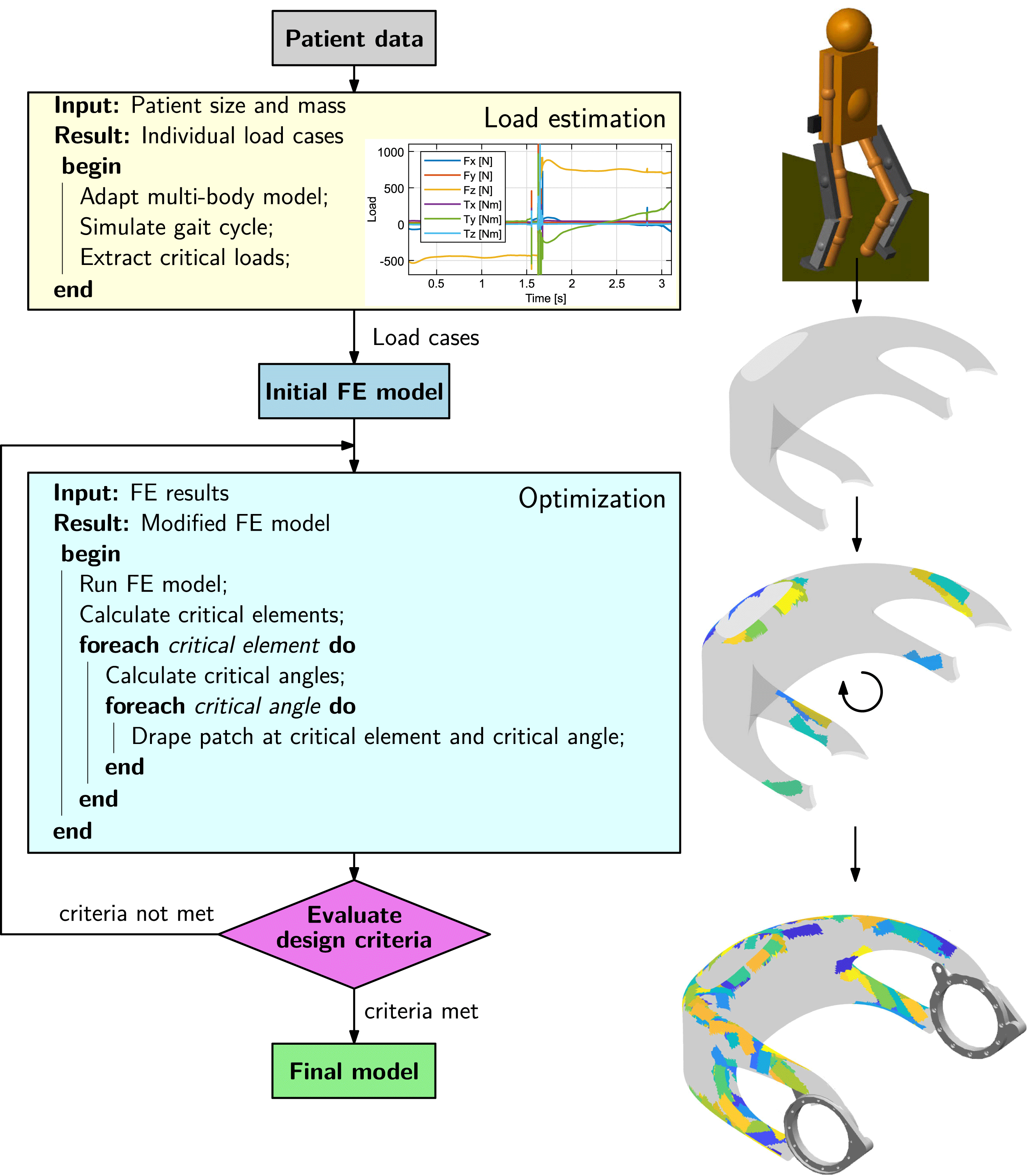
Figure 6. Process steps for load-bearing structure individualization.
The exoskeleton hip loads are calculated from a multibody model of the system, represented by two subsystems: an exoskeleton and a patient. The model is parameterized using patients’ masses and sizes as input parameters. The walking motion is then simulated and the loads on the exoskeleton hip over the gait cycle are computed, from which the critical load cases are extracted. Detailed information on the multibody load estimation model can be found in appendix C.
The optimization method applies fiber patches on a predefined base structure. It is based on sequentially placing fiber patches on a finite element (FE) model, using critical element and angle selection to locate and orientate the patches, until specified design criteria are met.
An underlying routine at first determines the critical locations to be reinforced in a structure depending on the design criteria. From the analysis of the FE results, critical elements are selected. These critical elements define where the reinforcement patches are added. In a second routine, optimal patch fiber angles are computed based on principal stress information. Finally, after the critical angles have been defined for all critical elements, the patches are draped on the mesh. The draping algorithm determines which elements of the model have to be modified and changes the layup of the relevant elements by inserting an additional ply thickness and angle into the stacking sequence.
Thus, a structure is reinforced with fiber patches, being applied at optimal locations with optimal fiber angles, leading to highly efficient, individualized structural solutions. Details on the patch optimization algorithm are given in a separate publication (Kussmaul et al. Reference Kussmaul, Jónasson, Zogg and Ermanni2019).
5 Results
The patient-individualized design of hip structures is demonstrated for a statistical 50.1 kg heavy 5th percentile female (Fryar et al. Reference Fryar, Gu, Ogden and Flegal2016) and for a 85.0 kg heavy male user. Table 1 lists the key design parameters, which are used with the 3D scan data for the individualization. As it can be seen, the values for body size and mass differ significantly for a female and a male patient. Moreover, the data is required to determine the patient-individual load cases.
Table 1. Patients’ masses and sizes

5.1 Design
5.1.1 Geometrical individualization
The geometric fitting of the hip design to a specific patient with respect to body shape and correct positioning to HJCs can be performed by applying the individualization process described in Section 4.1. For illustration, Figure 7 shows two hip component designs generated for a 85 kg heavy male and for a 5th percentile female. The width of the hip component
![]() $w_{E}$
is based on the torso width
$w_{E}$
is based on the torso width
![]() $w_{P}$
plus a distance for softening padding between hip component and pilot.
$w_{P}$
plus a distance for softening padding between hip component and pilot.
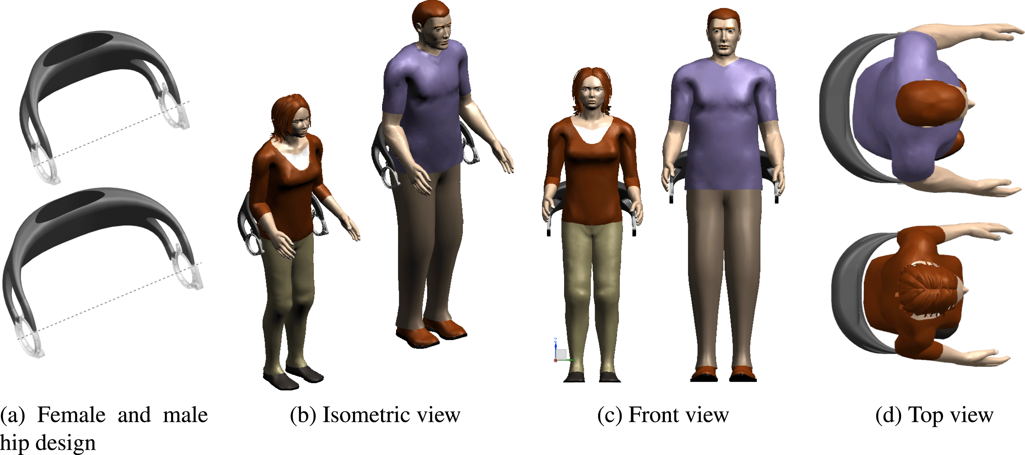
Figure 7. Individualized exoskeleton hips for 50.1 kg 5th percentile female and 85 kg male patient.
5.1.2 Structural individualization
Individualization of the load-bearing structure comprises two steps, namely, at first, the determination of the acting loads on the hip depending on the respective exoskeleton pilot and, second, the patch reinforcement of the base hip structure until a valid design solution is found.
5.1.2.1 Load case and design objectives
The loads acting on the exoskeleton hip structure are found by applying the patient data given in Table 1 to the multibody model. The computed loads acting on the hip are given in Table 2.
Table 2. Moments
![]() $\boldsymbol{M}$
and constraints
$\boldsymbol{M}$
and constraints
![]() $\unicode[STIX]{x1D6F7}^{\star }$
,
$\unicode[STIX]{x1D6F7}^{\star }$
,
![]() $\overline{u}^{\star }$
on the hip component for a 50.1 kg heavy 5th percentile female and an 85 kg heavy male patient
$\overline{u}^{\star }$
on the hip component for a 50.1 kg heavy 5th percentile female and an 85 kg heavy male patient

Additionally, the table shows the design targets for the patch optimization routine. For all load cases, a maximum failure index
![]() $\unicode[STIX]{x1D6F7}^{\star }\leqslant 1.0$
must be achieved. The failure index computation is detailed in appendix B. Moreover, a maximum displacement magnitude constraint is specified as
$\unicode[STIX]{x1D6F7}^{\star }\leqslant 1.0$
must be achieved. The failure index computation is detailed in appendix B. Moreover, a maximum displacement magnitude constraint is specified as
![]() $\overline{u}^{\star }\leqslant 19.0$
mm. Application of the loads is illustrated in Figure 8(a).
$\overline{u}^{\star }\leqslant 19.0$
mm. Application of the loads is illustrated in Figure 8(a).
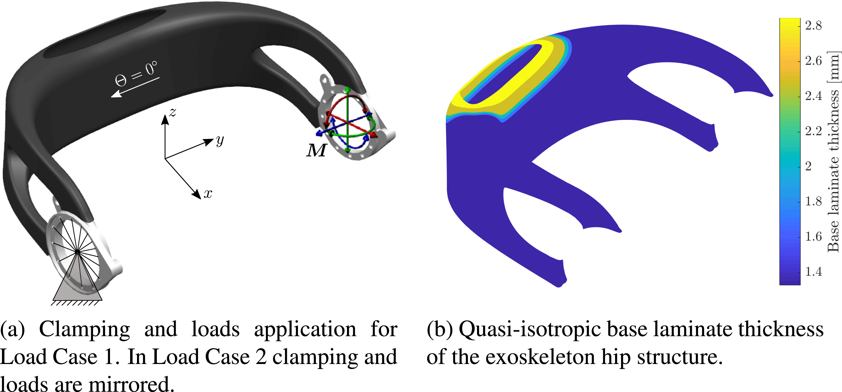
Figure 8. Exoskeleton hip load cases and base laminate.
5.1.2.2 Base laminate
The 5th percentile female load case serves as the lower bound definition of the expected load spectrum acting on an individualized hip. It is used to determine a fixed base laminate from continuous carbon fiber layers, which remains unaltered for all potential patient-individual exoskeleton designs.
The base laminate comprises CFRP weave and has a quasi-isotropic layup. Its thickness is shown in Figure 8(b). The material properties can be found in Table 3.
For the hip structure consisting only of the base laminate, a maximum failure index
![]() $\unicode[STIX]{x1D6F7}_{\max }=0.989$
and a maximum displacement magnitude
$\unicode[STIX]{x1D6F7}_{\max }=0.989$
and a maximum displacement magnitude
![]() $\overline{u}_{\max }=13.8$
mm is found, when the 5th percentile female load cases are applied. Hence, the base layup is a valid design solution for the lower bound load cases.
$\overline{u}_{\max }=13.8$
mm is found, when the 5th percentile female load cases are applied. Hence, the base layup is a valid design solution for the lower bound load cases.
5.1.2.3 Patch optimization
Applying the 85 kg male patient load cases on the base laminate hip structure, a maximum failure index
![]() $\unicode[STIX]{x1D6F7}_{\max }=1.558$
and a maximum displacement magnitude
$\unicode[STIX]{x1D6F7}_{\max }=1.558$
and a maximum displacement magnitude
![]() $\overline{u}_{\max }=31.2$
mm is calculated, exceeding by far the limits given in Table 2. Consequently, the optimization routine is applied in order to find patch reinforcements to be placed on the exoskeleton hip structure. The patches are of constant rectangular shape with dimensions of
$\overline{u}_{\max }=31.2$
mm is calculated, exceeding by far the limits given in Table 2. Consequently, the optimization routine is applied in order to find patch reinforcements to be placed on the exoskeleton hip structure. The patches are of constant rectangular shape with dimensions of
![]() $60\times 20$
mm and consist of unidirectional (UD) CFRP material.
$60\times 20$
mm and consist of unidirectional (UD) CFRP material.
Figure 9 shows the evolution of design constraints and the mass of the hip laminate as optimization is carried out as well as the final individualized patch reinforcement solution. The strength and stiffness constraints are fulfilled after 222 patches have been added to the base laminate of the component. A laminate mass increase of 20.1% results. However, because of placing patches in optimal location at optimal orientations, at the same time, stiffness is increased by 78.2% and strength by 99.2%. Hence, load-tailoring with patched laminates allows for the realization of highly efficient lightweight solutions and helps avoiding the typical over-dimensioning of biomedical structures.
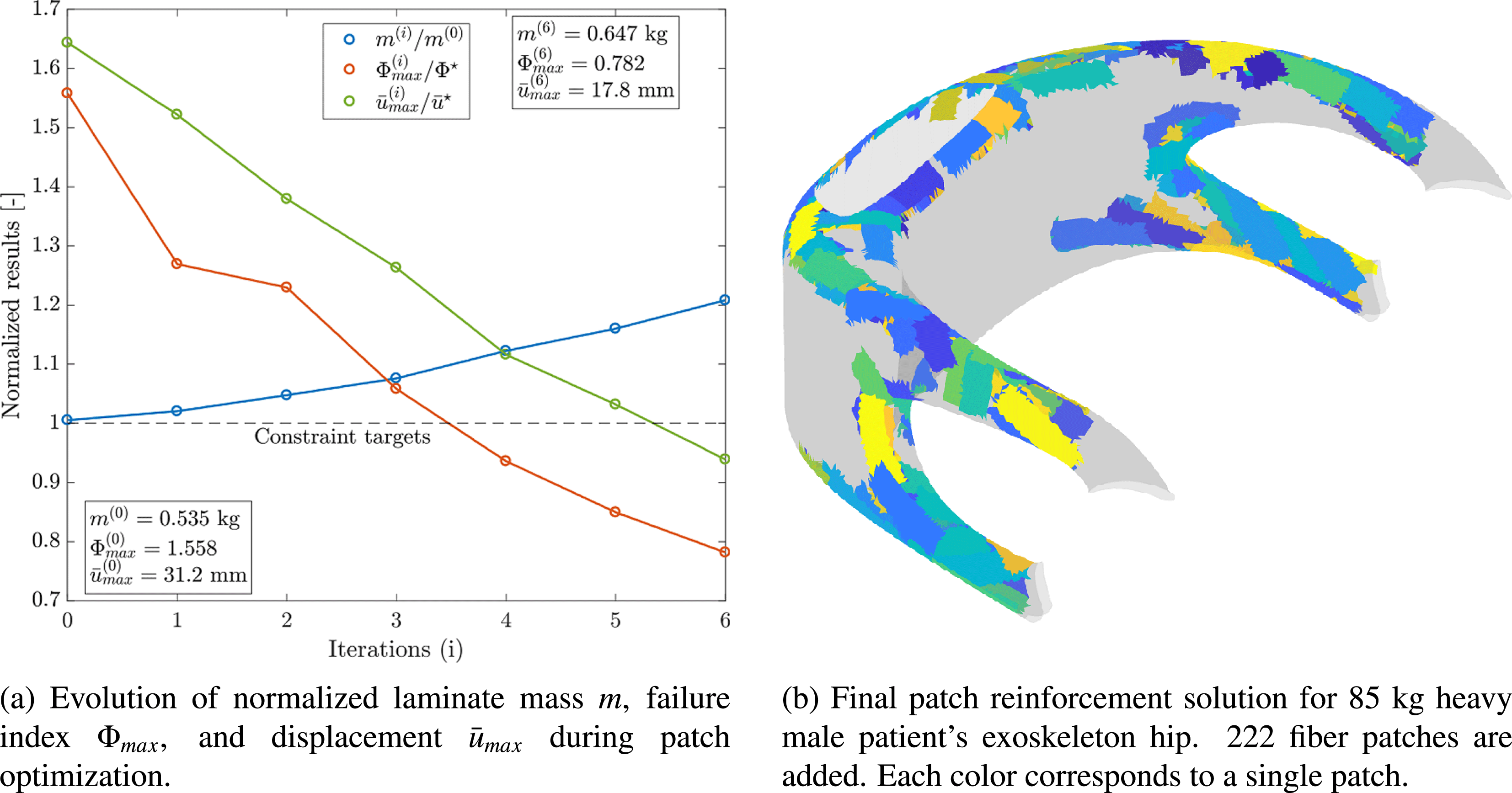
Figure 9. Load-bearing structure individualization of exoskeleton hip (Kussmaul et al. Reference Kussmaul, Jónasson, Zogg and Ermanni2019).
5.2 Manufacturing
Figure 10 shows the results of the manufacturing of an exoskeleton hip individualized for an 85 kg heavy male patient.
Figure 10(a) shows the final part after post-processing. Post-processing steps include removal of the salt filling, partial removal of the AM core, and surface finishing by sanding and polishing.
Figure 10(b) shows the ABS battery holder, which is co-cured to the CFRP shell. The battery holder was integrated in the additively manufactured ABS core. Rated breaking lines around the battery holder allow for the separation of core and battery holder after the curing process. Because the battery holder section of the core was not covered with release foil, it remains bonded to the inner surface of the CFRP shell.
The surrounding core sections were covered with release foil and thus could be removed. The removed core fragments are shown in Figure 10(c). It can be seen how the core is dissected along the breaking lines.
Figure 10(d) depicts the metal inserts, which are co-cured to the CFRP shell.
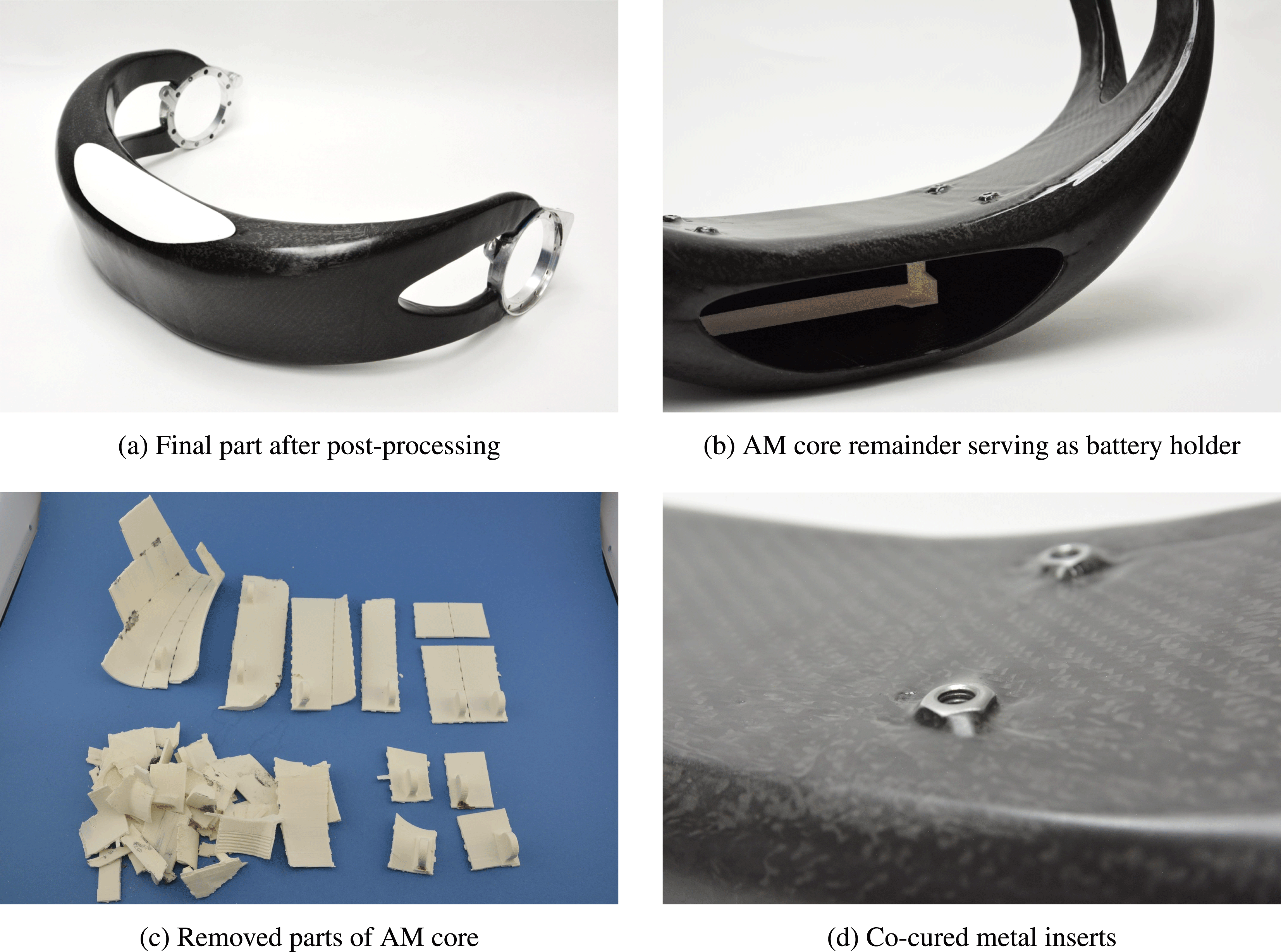
Figure 10. Manufacturing results.
5.3 Weight
The final mass of the AM–CFRP exoskeleton hip designed for a 85 kg heavy male patient is 1447 g. As shown in Figure 11, compared to the mass of the adjustable aluminum reference hip, 3618 g, a mass reduction of 60% is achieved.
Major mass contributor is the CFRP shell weighing 730 g including the patches, whereas the metal LIE amount for 537 g. The additively manufactured ABS core has a mass of 514 g; however, as the core is partially removed, only 157 g of its material remain in the final structure. Hence, a significant weight-saving of 357 g is achieved through partial core removal.
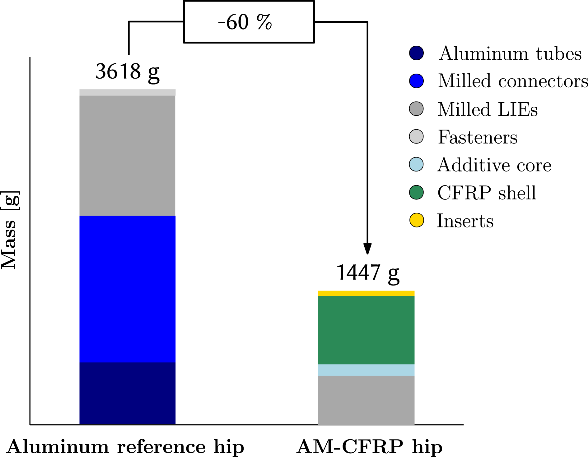
Figure 11. Weight comparison.
5.4 Ultimate strength test
A quasi-static strength test was carried out, in which the structure was loaded until failure. The exoskeleton hip was fixed at its LIE on one side. Moments
![]() $M_{x}$
,
$M_{x}$
,
![]() $M_{y}$
were introduced simultaneously on the opposite side using double Cardan joints, allowing free rotation of the respective LIE, as shown in Figure 12(a).
$M_{y}$
were introduced simultaneously on the opposite side using double Cardan joints, allowing free rotation of the respective LIE, as shown in Figure 12(a).
Failure of the tested AM–CFRP component occurred at a load of
![]() $M_{y}=875$
Nm and
$M_{y}=875$
Nm and
![]() $M_{x}=462$
Nm. Hence, the structure withstands a static load of
$M_{x}=462$
Nm. Hence, the structure withstands a static load of
![]() ${\sim}3$
times the operating load. While this seems a lot, it is mentioned that the exoskeleton hip was designed aiming for a stiffness objective and for fatigue resistance with a maximum strain allowable of 0.4%.
${\sim}3$
times the operating load. While this seems a lot, it is mentioned that the exoskeleton hip was designed aiming for a stiffness objective and for fatigue resistance with a maximum strain allowable of 0.4%.
As can be seen in Figure 12(b), the AM–CFRP structure failed due to fiber fracture originating from the edge of the opening of the CFRP shell. The location of failure corresponds to FEA predictions and is plausible because significant stress concentrations are induced around the opening.
No failure could be observed at the co-cured metal/CFRP interfaces; however, acoustic emission measurements suggested a certain amount of interface damage.

Figure 12. Ultimate strength test setup and results.
6 Discussion
The case study highlights how multiple technologies in the field of manufacturing, e.g. AM and CFRP, and digitization, e.g. 3D scanning, digital design, and optimization, can be combined in a way that makes use of their respective strengths and thus provides benefits for the design and manufacturing of biomedical structures. In the following, it is discussed how well the requirements for these structures are fulfilled and where further improvements are necessary.
6.1 Individualization and process chain
The key contribution of the presented work is the demonstration of a process chain that customizes a biomedical structure to a specific pilot by applying a geometric adaption together with a tailoring of the load-bearing behavior of the composite structure. The process chain employs recent advancements in the optimization of patched laminates and optimizes the composite structure for each individual pilot. Compared to a pre-optimized structure, the approach requires additional computational effort but avoids over-dimensioning and leads to a high-performance component. The case study shows that such an approach is possible at an increased level of design complexity with 3D double-curved surfaces that feature openings and holes. Although the digital process chain is yet to be fully automated in a streamlined and integrated design framework without the need for any manual steps, it contains all necessary building blocks. Manual steps that are to be automated include the acquisition and post-processing of the scan data, the transfer of data between the interfaces of the building blocks, and a manufacturability check of the geometries.
The case study highlights the advantage of individualizing the load-bearing behavior of a composite structure by comparing the resulting structure for a 5th percentile female and a 85 kg heavy male. In this respect, the geometric model of the hip component is only varied regarding the hip width and hip depth to showcase the influence of a tailored composite layup. Of course, the number of design parameters may be further extended and also include other dimensions, which describe the positioning of the component relative to the pilot (e.g. relative height of component, local distance to pilot) as well as the shape of the cross-section of the component. In this regard, a sizing optimization can be performed prior to the laminate optimization to explore a larger design space and gain further potential for a lightweight design.
Although the definition of multiple parameters makes it possible to increase the model flexibility, it has to be noted that the successful update of the CAD geometry may fail in case of a larger design space, thereby making the robustness of the model a critical factor. Within this work, the update of the CAD model was examined for real-world scans as shown in Figure 5 and boundary cases of the design space such as a 5th percentile female given in Figure 7 using mankind models within the CAD system. The quantification of model robustness and automated testing of the CAD model are regarded as next important steps together with the examination of different strategies to define template-based models that feature multi-disciplinary aspects of design and manufacturing (Amadori et al. Reference Amadori, Tarkian, Ölvander and Krus2012). Further research and methodologies may also be needed to investigate how robust and flexible CAD models can be efficiently developed and tested in order to create digital process chains for individualization.
6.2 Manufacturing
For the examined case study, the FDM-fabricated and salt-filled core proved to be a stable and cost-efficient manufacturing tool. The partial removal of the core allows for a weight reduction; however, it requires a certain amount of manual labor and needs to be further improved. As it can be seen in Figure 10(c), some core pieces did not break along the intended breaking lines but perpendicular to them. This is attributed to the influence of the building direction within the FDM process on the fracture behavior. To achieve an optimized and full removal of the core, further investigation is required regarding the choice of material and process, the design of the core and integrated breaking lines, and the analysis of the occurring fracture mechanisms.
For instance, instead of FDM and ABS, other AM processes and materials such as SLS of polyamide may be applicable for break-out cores and minimize the anisotropic dependency between building direction and orientation of breaking line (Türk et al. Reference Türk, Ebnoether, Zogg and Meboldt2018a ). It has to be noted that the core pieces require a certain degree of flexibility for the pull-out process and must easily rupture along the intended lines. In this regard, also the design and layout of the breaking lines (e.g. with perforation) and choice of the fracture mode (e.g. opening, in-plane shear, out-of-plane shear) are important influence factors. Besides the use of breaking lines, other mechanisms such as folding or interlocking mechanisms may also provide alternative solutions. In addition, the shape deviation of the manufactured composite shell from the designed shape due to the compliance of the thin-walled, core structure may be further characterized for salt and similar filler materials.
6.3 Cost efficiency
Besides the required engineering effort in design and development, cost efficiency is determined by the effort and manual labor needed for fabrication. In this respect, it has to be noted that the employed manufacturing process depends on several manual and time-consuming steps, such as the preparation of the core or the layup of the prepreg material. Even though the design-assisted manufacturing approach minimizes the amount of separate parts and uses a single-shot autoclave curing process, the manufacturing route is only economically reasonable for small-series production. Possibilities for improvement include the use of tooling aids for prepreg layup or technologies such as automated fiber placement. Especially FPP appears as a promising option for the automated small- to medium-scale production of individualized lightweight structures. In contrast to endless fiber placement processes, it allows for a higher geometrical complexity. Moreover, information on patch placement location and orientation are directly available as the output of the optimization framework.
6.4 Testing
The strength test showed that the mechanical structure, especially the aluminum–composite interface, is reliable and able to carry high loads in quasi-static loading conditions. In a next step, it is necessary to examine the fatigue strength of the structure by conducting a test with dynamic loading as it occurs in the operation of OPE structures.
7 Conclusions
In this work, a novel manufacturing route for individualized lightweight structures using AM and CFRP as well as a digitized end-to-end design chain for their efficient design was presented.
The work contributes to the ongoing research on the OPE technology, which is driven by an increasing demand for well-performing and, at the same time, efficiently producible solutions. The herein proposed methods allow for the realization of to date unrivaled high-performance individualized biomedical structures. The efficient automated design process chain and the sustainable manufacturing route make these devices more accessible for commercial applications.
The example of an individualized AM–CFRP exoskeleton hip structure shows a significantly better structural performance compared to a state-of-the-art solution.
Future research will focus on further advancement of automation in the manufacturing process, which is feasible by combining 3D-printed lamination cores with automated fiber patch application using patch placement robots (Cevotec 2017). This will eventually lead to the ultimate goal of a fully automated production of individualized, light, stiff, and strong biomedical devices that provide further benefits for people with disabilities in their musculoskeletal system.
Contribution
The first and second author contributed equally to the work.
Acknowledgment
Funding for this study has been provided by the Advanced Manufacturing initiative of the ETH Board, under the CFRP-AM, Individualized cost-effcient and sustainable ultra-lightweight structural components project.
Appendix A. Material properties
Table 3. Material properties

Appendix B. Laminate failure index computation
In this research, the laminate failure index is evaluated from a maximum-strain criterion formulated as
with
![]() $\unicode[STIX]{x1D716}_{11}$
,
$\unicode[STIX]{x1D716}_{11}$
,
![]() $\unicode[STIX]{x1D716}_{22}$
,
$\unicode[STIX]{x1D716}_{22}$
,
![]() $\unicode[STIX]{x1D716}_{12}$
denoting the layer strains in local coordinates. In the structural model,
$\unicode[STIX]{x1D716}_{12}$
denoting the layer strains in local coordinates. In the structural model,
![]() $\unicode[STIX]{x1D6F7}$
is computed in every element for all layers.
$\unicode[STIX]{x1D6F7}$
is computed in every element for all layers.
Appendix C. Load estimation model
In order to load-tailor individualized hip components, a load assessment model, providing individualized load cases, is required.
The hip loads are calculated from a multibody model of the exoskeleton/patient system. The schematic setup of the model is shown in Figure 13. Two subsystems are used to represent the system, an exoskeleton and a patient. The model is parameterized, using patients’ masses and sizes as input parameters. The walking motion is then simulated and the loads on the exoskeleton hip over the gait cycle are computed, from which the critical load cases are extracted.

Figure 13. Multibody load assessment model of exoskeleton hip structure.
The exoskeleton is modeled as two identical legs and a hip structure. Three mass concentrations located on each leg represent the mass of the foot, shank, and thigh, and an additional mass concentration represents the hip. Each leg consists of two rigid frames, a shank and a thigh, connected with a revolute joint. A revolute joint on top of the thigh then connects it to the hip structure. The revolute joints represent the knee and hip motors of the exoskeleton. To ambulate the exoskeleton, knee and hip angle time series are fed into the model. These time series are obtained from the adjustable foot trajectory used by the VariLeg 2 exoskeleton, which is based on motion capture data (Schrade et al. Reference Schrade, Dätwyler, Stücheli, Studer, Türk, Meboldt and Lambercy2018).
The patient is modeled as a series of frames and point masses with joints. Each body segment is represented by a point mass, located at its center of gravity as found in Richard & Kullmer (Reference Richard and Kullmer2014). The patient is connected to the exoskeleton with three bushings, one on the hip and two on each thigh. To prevent the exoskeleton from falling, the hip is connected to the world-fixed coordinate system, which mimics the effect of the crutches used by exoskeleton pilots for balancing. On the bottom of the feet, a spring damper element, with a ground contact force, using a stick–slip continuous friction law, is used.
Validation of the multibody model is done using experimental data from an in situ load assessment of the hip component, while performing tasks as walking and climbing stairs. This load assessment uses strain gauges applied to the loupe-shaped motor mount components as seen in Figure 14. The measured strains are then enforced on an FE model of the LIE and the resulting reaction moments at the motor mounting points are computed. For the measured paraplegic patients weighing 85 kg, the ventral–dorsal (rx) peak moment
![]() $M_{x}$
is 150 Nm, and the medial–lateral (ry) peak moment
$M_{x}$
is 150 Nm, and the medial–lateral (ry) peak moment
![]() $M_{y}$
is found to be 245 Nm.
$M_{y}$
is found to be 245 Nm.
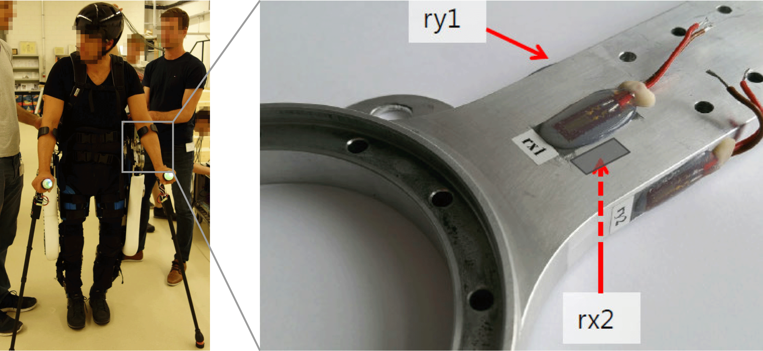
Figure 14. In situ load assessment with strain gauges on exoskeleton hip load introductions.
For tuning the model, its input parameters are set to those of the paraplegic patients, the multibody model is run, and from the load-over-time curves, the critical loading is extracted. The model results are then compared to the measured data. After parameter tuning in the model, its results are in good agreement with the load assessment as can be seen in Table 4. The multibody model can be therefore used to obtain individualized loadings for patients of different sizes and weights.
Table 4. Multibody model validation results for 85 kg heavy male patient


