1. Introduction
Single frequency lasers near 2 ![]() $\mathrm {\mu} $m, which play a significant role in many applications such as coherent LIDAR, coherent beam combining, nonlinear frequency conversion, medicine, atmospheric sensing, and spectroscopy, have attracted intense interest and been widely investigated[Reference Shen, Clarkson, Cooper and Williams1–Reference Geng, Wang, Luo, Jiang and Amzajerdian12]. In recent years, 2
$\mathrm {\mu} $m, which play a significant role in many applications such as coherent LIDAR, coherent beam combining, nonlinear frequency conversion, medicine, atmospheric sensing, and spectroscopy, have attracted intense interest and been widely investigated[Reference Shen, Clarkson, Cooper and Williams1–Reference Geng, Wang, Luo, Jiang and Amzajerdian12]. In recent years, 2 ![]() $\mathrm {\mu} $m single frequency fiber lasers have undergone rapid development[Reference Shi, Petersen, Nguyen, Yao, Chavez-Pirson, Peyghambarian and Yu11–Reference Guo, Shen, Long and Wang22] since fiber lasers have outstanding advantages including high efficiency, considerable compactness, convenience for thermal management, high beam quality and excellent stability. To realize single frequency fiber laser near 2
$\mathrm {\mu} $m single frequency fiber lasers have undergone rapid development[Reference Shi, Petersen, Nguyen, Yao, Chavez-Pirson, Peyghambarian and Yu11–Reference Guo, Shen, Long and Wang22] since fiber lasers have outstanding advantages including high efficiency, considerable compactness, convenience for thermal management, high beam quality and excellent stability. To realize single frequency fiber laser near 2 ![]() $\mathrm {\mu} $m, distributed Bragg reflector (DBR)[Reference Zhang, Boyland, Sahu, Clarkson and Ibsen15] and distributed-feedback (DFB)[Reference Geng, Wang, Luo, Jiang and Amzajerdian12, Reference Voo, Sahu and Ibsen19] techniques have been employed, the output power is limited and should be further amplified for practical applications. At present, most of the reported high power single frequency fiber lasers near 2
$\mathrm {\mu} $m, distributed Bragg reflector (DBR)[Reference Zhang, Boyland, Sahu, Clarkson and Ibsen15] and distributed-feedback (DFB)[Reference Geng, Wang, Luo, Jiang and Amzajerdian12, Reference Voo, Sahu and Ibsen19] techniques have been employed, the output power is limited and should be further amplified for practical applications. At present, most of the reported high power single frequency fiber lasers near 2 ![]() $\mathrm {\mu} $m are achieved based on bulk configuration[Reference Goodno, Book and Rothenberg3, Reference Pearson, Kim, Zhang, Ibsen, Sahu and Clarkson4]. Meanwhile, monolithic fiber lasers based on all-fiber configuration possess the advantages of being more stable and practical, so it is really attractive to investigate and develop single frequency fiber lasers near 2
$\mathrm {\mu} $m are achieved based on bulk configuration[Reference Goodno, Book and Rothenberg3, Reference Pearson, Kim, Zhang, Ibsen, Sahu and Clarkson4]. Meanwhile, monolithic fiber lasers based on all-fiber configuration possess the advantages of being more stable and practical, so it is really attractive to investigate and develop single frequency fiber lasers near 2 ![]() $\mathrm {\mu} $m employing monolithic fiber configuration[Reference Fang, Shi, Kieu, Petersen, Chavez-Pirson and Peyghambarian20]. An admirable previous work has been done by Gapontsev et al., who demonstrated a 20 W monolithic single frequency fiber amplifier at 1.93
$\mathrm {\mu} $m employing monolithic fiber configuration[Reference Fang, Shi, Kieu, Petersen, Chavez-Pirson and Peyghambarian20]. An admirable previous work has been done by Gapontsev et al., who demonstrated a 20 W monolithic single frequency fiber amplifier at 1.93 ![]() $\mathrm {\mu} $m in 2007[Reference Gapontsev, Platonov, Meleshkevich, Shkurikhin, Agger, Varming and Poylsen18].
$\mathrm {\mu} $m in 2007[Reference Gapontsev, Platonov, Meleshkevich, Shkurikhin, Agger, Varming and Poylsen18].
In this paper, we demonstrate a monolithic single frequency fiber amplifier at 1.97 ![]() $\mathrm {\mu} $m based on master oscillator power amplifier (MOPA) configuration. The maximum output power has reached 51.5 W with slope efficiency of 45%. There was no amplified spontaneous emission (ASE) or stimulated Brillouin scattering (SBS) effect observed in the amplifier, which means the output power can be improved further if the the pump power is increased.
$\mathrm {\mu} $m based on master oscillator power amplifier (MOPA) configuration. The maximum output power has reached 51.5 W with slope efficiency of 45%. There was no amplified spontaneous emission (ASE) or stimulated Brillouin scattering (SBS) effect observed in the amplifier, which means the output power can be improved further if the the pump power is increased.
2. Experimental setup
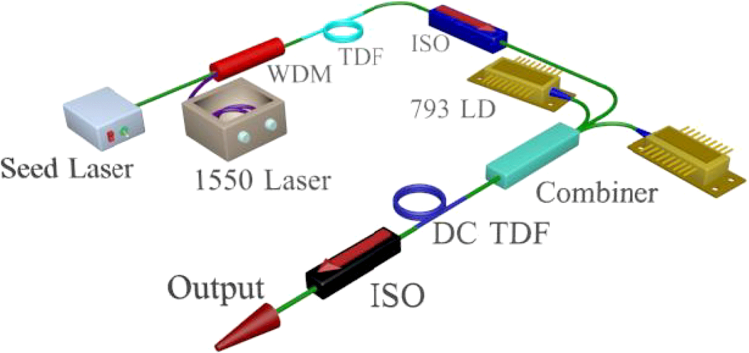
In the MOPA system, the single frequency seed fiber laser based on ultrashort cavity[Reference Geng, Wu and Jiang16] operates at 1.97 ![]() $\mathrm {\mu} $m and has output power of 35 mW, and the linewidth is less than 100 kHz. Figure 1 shows the two-stage Tm-doped fiber pre-amplifier. The first stage of the pre-amplifier consists of a 1550 nm pump laser, a 1550/2000 wavelength division multiplexer (WDM), an isolator (ISO) and a piece of 2.5 m long single cladding Tm-doped fiber (NA is 0.15) with core diameter of 9
$\mathrm {\mu} $m and has output power of 35 mW, and the linewidth is less than 100 kHz. Figure 1 shows the two-stage Tm-doped fiber pre-amplifier. The first stage of the pre-amplifier consists of a 1550 nm pump laser, a 1550/2000 wavelength division multiplexer (WDM), an isolator (ISO) and a piece of 2.5 m long single cladding Tm-doped fiber (NA is 0.15) with core diameter of 9 ![]() $\mathrm {\mu} $m and cladding diameter of 125
$\mathrm {\mu} $m and cladding diameter of 125 ![]() $\mathrm {\mu} $m. The second stage of the pre-amplifier employs a
$\mathrm {\mu} $m. The second stage of the pre-amplifier employs a ![]() $(2 + 1) \times 1$ signal-pump combiner and two 793 nm laser diodes (LDs). The amplified 2
$(2 + 1) \times 1$ signal-pump combiner and two 793 nm laser diodes (LDs). The amplified 2 ![]() $\mathrm {\mu} $m laser signal was injected into a piece of 8 m long double cladding Tm-doped fiber (DC-TDF) with core diameter of 10
$\mathrm {\mu} $m laser signal was injected into a piece of 8 m long double cladding Tm-doped fiber (DC-TDF) with core diameter of 10 ![]() $\mathrm {\mu} $m and inner cladding diameter of 125
$\mathrm {\mu} $m and inner cladding diameter of 125 ![]() $\mathrm {\mu} $m. The Tm-doped fiber’s NA is 0.15 and the absorption coefficient at 793 nm is 3 dB/m. The fiber pre-amplifier finally amplified the seed laser’s power to 3 W.
$\mathrm {\mu} $m. The Tm-doped fiber’s NA is 0.15 and the absorption coefficient at 793 nm is 3 dB/m. The fiber pre-amplifier finally amplified the seed laser’s power to 3 W.

Figure 1. Schematic diagram of the Tm-doped fiber pre-amplifier. WDM, wavelength division multiplexer, TDF, Tm-doped fiber; ISO, isolator; DC-TDF, double cladding Tm-doped fiber.

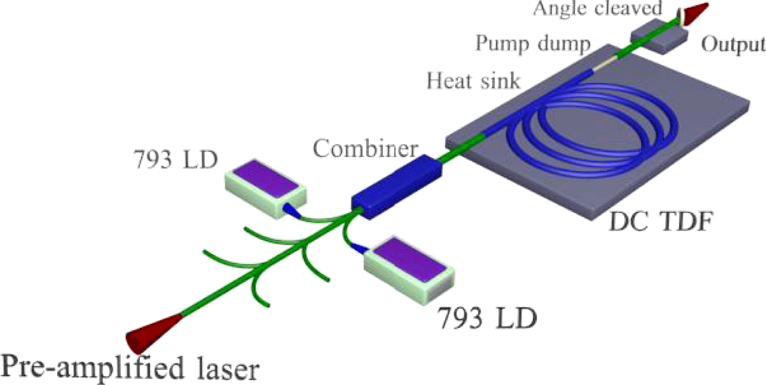
Figure 2. Schematic diagram of the main fiber amplifier.
The main fiber amplifier’s configuration is shown in figure 2. A ![]() $(6 + 1) \times 1$ signal-pump combiner was employed to combine the pre-amplified 2
$(6 + 1) \times 1$ signal-pump combiner was employed to combine the pre-amplified 2 ![]() $\mathrm {\mu} $m signal laser and the 793 nm pump laser together. The 3 m long large mode area (LMA) DC-TDF with core and inner cladding diameters of 25 and 250
$\mathrm {\mu} $m signal laser and the 793 nm pump laser together. The 3 m long large mode area (LMA) DC-TDF with core and inner cladding diameters of 25 and 250 ![]() $\mathrm {\mu} $m acted as the gain medium. The absorption coefficient of the LMA DC-TDF at 793 nm is about 8 dB/m. The output end of the combiner was fusion spliced to one end of the DC-TDF and coated with low refractive index polymer. A piece of 0.5 m 25/250 passive fiber was fusion spliced to the other end of the active fiber. The fusion splice joint of the active and passive laser was covered by gel with high refractive index to dump the unabsorbed pump power. Water-cooled heat sinks were employed to protect the fusion splice joint and active fiber from thermally-induced damage. The active fiber is coiled within a diameter of less than 12 cm to ensure good beam quality[Reference Koplow, Kliner and Goldberg23, Reference Li, Lou, Zhou, Dong, Wei and Li24]. The output end the passive laser was angle cleaved to avoid the unwanted reflection. The fusion splice joints in the MOPA system make it a really monolithic fiber configuration. The output power was measured at the angle cleaved end and the spectrum was recorded by an optical spectrum analyzer (OSA, YOKOGAWA) with resolution of 0.05 nm.
$\mathrm {\mu} $m acted as the gain medium. The absorption coefficient of the LMA DC-TDF at 793 nm is about 8 dB/m. The output end of the combiner was fusion spliced to one end of the DC-TDF and coated with low refractive index polymer. A piece of 0.5 m 25/250 passive fiber was fusion spliced to the other end of the active fiber. The fusion splice joint of the active and passive laser was covered by gel with high refractive index to dump the unabsorbed pump power. Water-cooled heat sinks were employed to protect the fusion splice joint and active fiber from thermally-induced damage. The active fiber is coiled within a diameter of less than 12 cm to ensure good beam quality[Reference Koplow, Kliner and Goldberg23, Reference Li, Lou, Zhou, Dong, Wei and Li24]. The output end the passive laser was angle cleaved to avoid the unwanted reflection. The fusion splice joints in the MOPA system make it a really monolithic fiber configuration. The output power was measured at the angle cleaved end and the spectrum was recorded by an optical spectrum analyzer (OSA, YOKOGAWA) with resolution of 0.05 nm.
3. Results and discussion
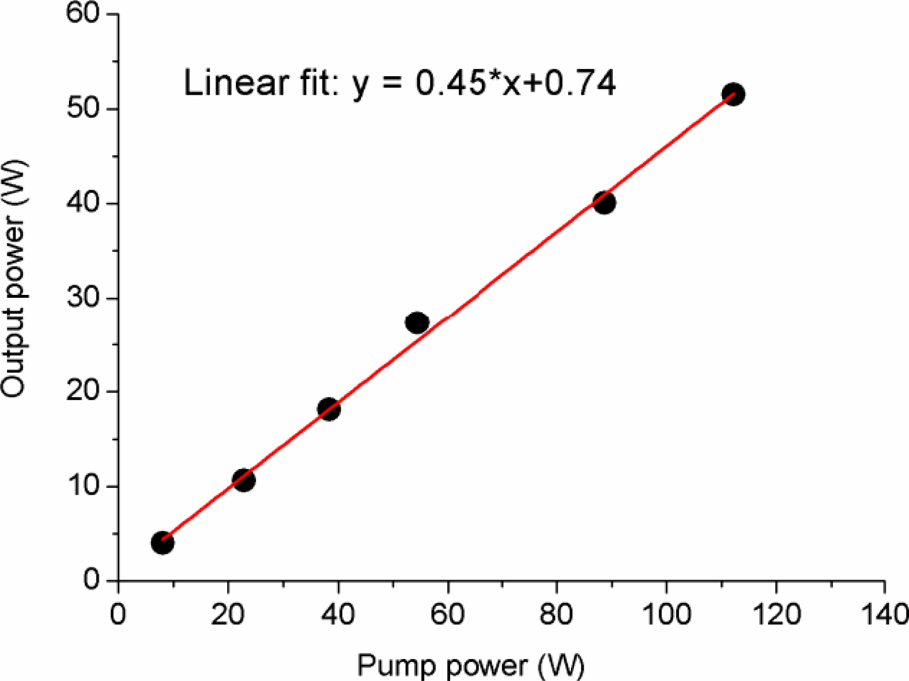
The output of the single frequency fiber amplifier is shown in figure 3. Only two of the six ports of the combiner were employed to launch 793 nm pump power into the active fiber. The maximum output power reaches 51.5 W when the pump power is about 112 W. The slope efficiency is 45% with respect to the launched pump power. One can find out that the output of the fiber amplifier is far from saturated, and more output power is realizable if the pump power is increased.

Figure 3. Single frequency fiber amplifier output with linear fit to slope efficiency of 45%.
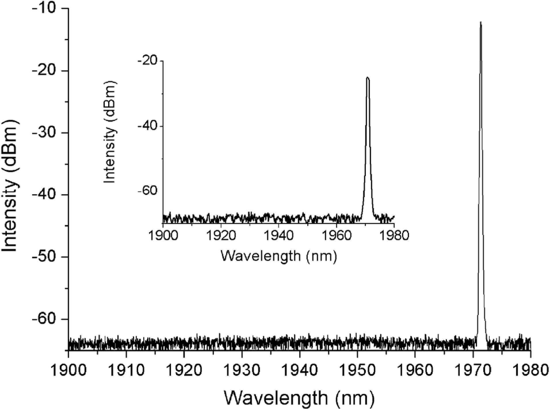
Figure 4 depicts the spectrum of the single frequency fiber amplifier with output power of 51.5 W. The single frequency fiber amplifier’s central wavelength is 1972.13 nm. No ASE or parasitic lasing is observed from the spectrum. The spectrum of the single frequency seed laser was inserted into figure 4. There are no evident differences observed between the spectra of the seed laser and the amplifier.

Figure 4. Spectrum of the single frequency fiber amplifier. Inset: spectrum of the seed laser.
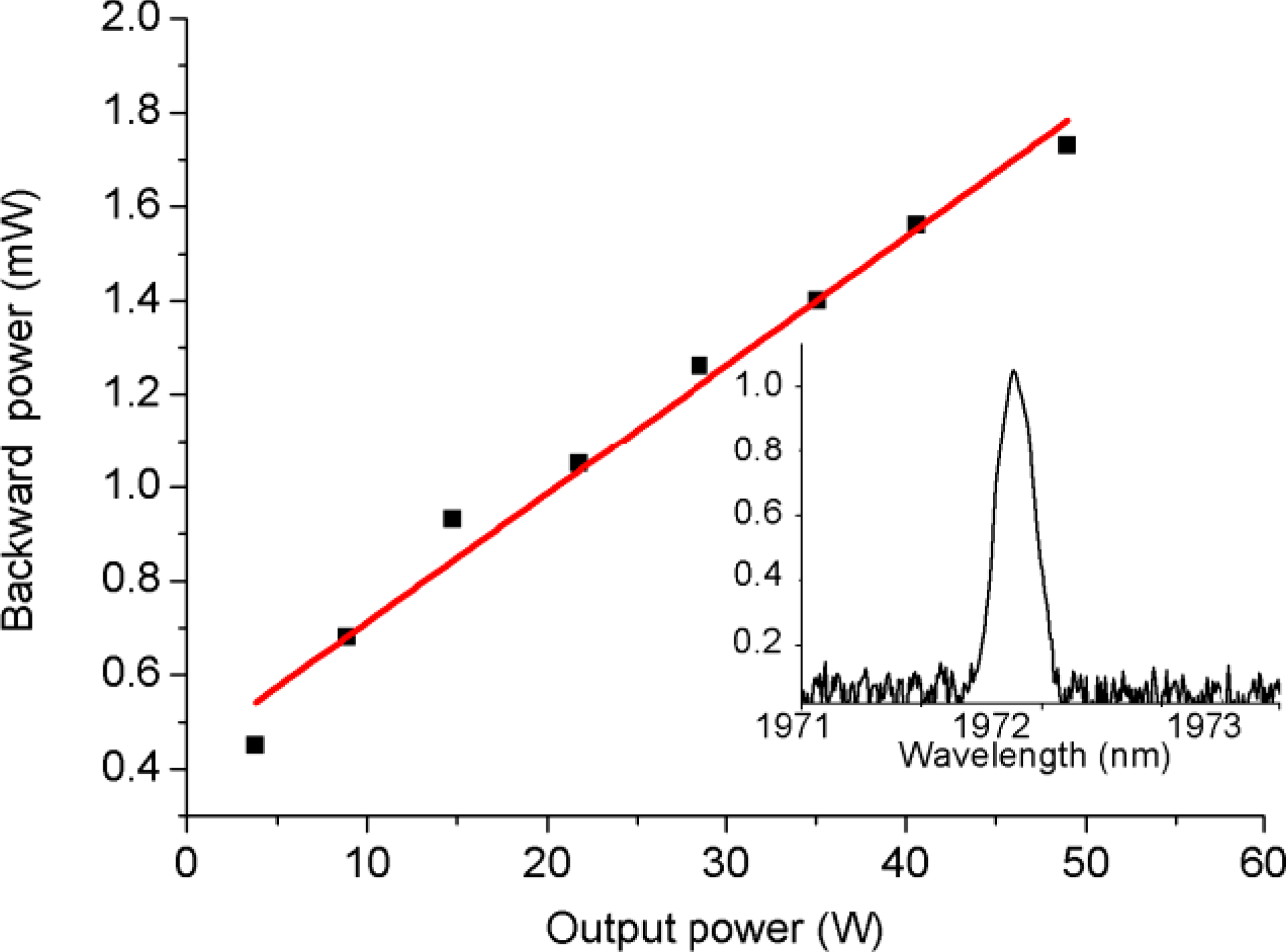
The backward power of the single frequency MOPA system was measured at a spare port of the signal-pump combiner in figure 2[Reference Wenbo, Xiaolin, Kai, Pu, Xiaojun and Bohong25, Reference Yunfeng, Peng, Bangcai, Rong and Ding26]. The results are shown in figure 5, from which we can find out that the backward power increases regularly as the output power mounts up, and the maximum backward power does not exceed 1.8 mW when the output power reaches 51.5 W. The spectrum of the backward power shows that there is no SBS existing in the amplifier. These results mean that the laser power is below the SBS threshold in the system, and the output power is not limited by the nonlinear effects in the fiber amplifier. Actually, the fiber length and core diameter in this experiment are nearly the same with those of Goodno et al. [Reference Goodno, Book and Rothenberg3], so we can coarsely estimate that the SBS threshold of our system is above several hundred watts. Much more parameters, such as bend radius, temperature gradient and Brillouin gain spectrum, should be considered to precisely estimate the SBS threshold in theoretical analysis.

Figure 5. Backward power of the single frequency fiber amplifier. Inset: spectrum of the backward power.
4. Conclusion
In conclusion, we experimentally demonstrate a monolithic single frequency fiber amplifier at 1.97 ![]() $\mathrm {\mu} $m. The system has all-fiber configuration and the maximum output power has reached 51.5 W. The slope efficiency with respect to the launched pump power is 45%. The spectrum of the fiber amplifier was measured and no ASE was observed. From the backward power results we have verified that there was no SBS effect in the amplifier. Higher output power of monolithic single frequency fiber amplifier near 2
$\mathrm {\mu} $m. The system has all-fiber configuration and the maximum output power has reached 51.5 W. The slope efficiency with respect to the launched pump power is 45%. The spectrum of the fiber amplifier was measured and no ASE was observed. From the backward power results we have verified that there was no SBS effect in the amplifier. Higher output power of monolithic single frequency fiber amplifier near 2 ![]() $\mathrm {\mu} $m is realizable if more pump power is available.
$\mathrm {\mu} $m is realizable if more pump power is available.


