Laser driven proton acceleration is an active field of research due to its high potential in reducing the size and cost of conventional accelerators. The acceleration scheme consists of a very high intensity (![]() ${>}10^{18}\ \mathrm{W\ cm}^{-2}$), high contrast (
${>}10^{18}\ \mathrm{W\ cm}^{-2}$), high contrast (![]() $10^{-10}$) laser pulse[Reference Wilks, Langdon, Cowan, Roth, Singh, Hatchett, Key, Pennington, MacKinnon and Snavely1, Reference Hatchett, Brown, Cowan, Henry, Johnson, Key, Koch, Langdon, Lasinski, Lee, Mackinnon, Pennington, Perry, Phillips, Roth, Sangster, Singh, Snavely, Stoyer, Wilks and Yasuike2]. The laser pulse interacts with a solid target, commonly a thin foil, from which high energy ions and protons are accelerated. Enhancement of the energy of the generated protons using a compact laser source (moderate intensity,
$10^{-10}$) laser pulse[Reference Wilks, Langdon, Cowan, Roth, Singh, Hatchett, Key, Pennington, MacKinnon and Snavely1, Reference Hatchett, Brown, Cowan, Henry, Johnson, Key, Koch, Langdon, Lasinski, Lee, Mackinnon, Pennington, Perry, Phillips, Roth, Sangster, Singh, Snavely, Stoyer, Wilks and Yasuike2]. The laser pulse interacts with a solid target, commonly a thin foil, from which high energy ions and protons are accelerated. Enhancement of the energy of the generated protons using a compact laser source (moderate intensity, ![]() $10^{17}\mbox{--}10^{19}\ \mathrm{W\ cm}^{-2}$) is a challenging but rewarding task due to the fact that the proton energy in traditional schemes scales as the electric field employed on the target[Reference Wilks and Kruer3]. One of the promising ways to increase the ion energy is the use of structured targets[Reference Kawata, Nagashima, Takano, Izumiyama, Kamiyama, Barada, Kong, Gu, Wang, Ma, Wang, Zhang, Xie, Zhang and Dai4], mainly nanotargets[Reference Margarone, Klimo, Kim, Prokůpek, Limpouch, Jeong, Mocek, Pšikal, Kim, Proška, Nam, Štolcová, Choi, Lee, Sung, Yu and Korn5]. In this kind of target the energy conversion efficiency from the laser to the proton beam is increased[Reference Nodera, Kawata, Onuma, Limpouch, Klimo and Kikuchi6].
$10^{17}\mbox{--}10^{19}\ \mathrm{W\ cm}^{-2}$) is a challenging but rewarding task due to the fact that the proton energy in traditional schemes scales as the electric field employed on the target[Reference Wilks and Kruer3]. One of the promising ways to increase the ion energy is the use of structured targets[Reference Kawata, Nagashima, Takano, Izumiyama, Kamiyama, Barada, Kong, Gu, Wang, Ma, Wang, Zhang, Xie, Zhang and Dai4], mainly nanotargets[Reference Margarone, Klimo, Kim, Prokůpek, Limpouch, Jeong, Mocek, Pšikal, Kim, Proška, Nam, Štolcová, Choi, Lee, Sung, Yu and Korn5]. In this kind of target the energy conversion efficiency from the laser to the proton beam is increased[Reference Nodera, Kawata, Onuma, Limpouch, Klimo and Kikuchi6].

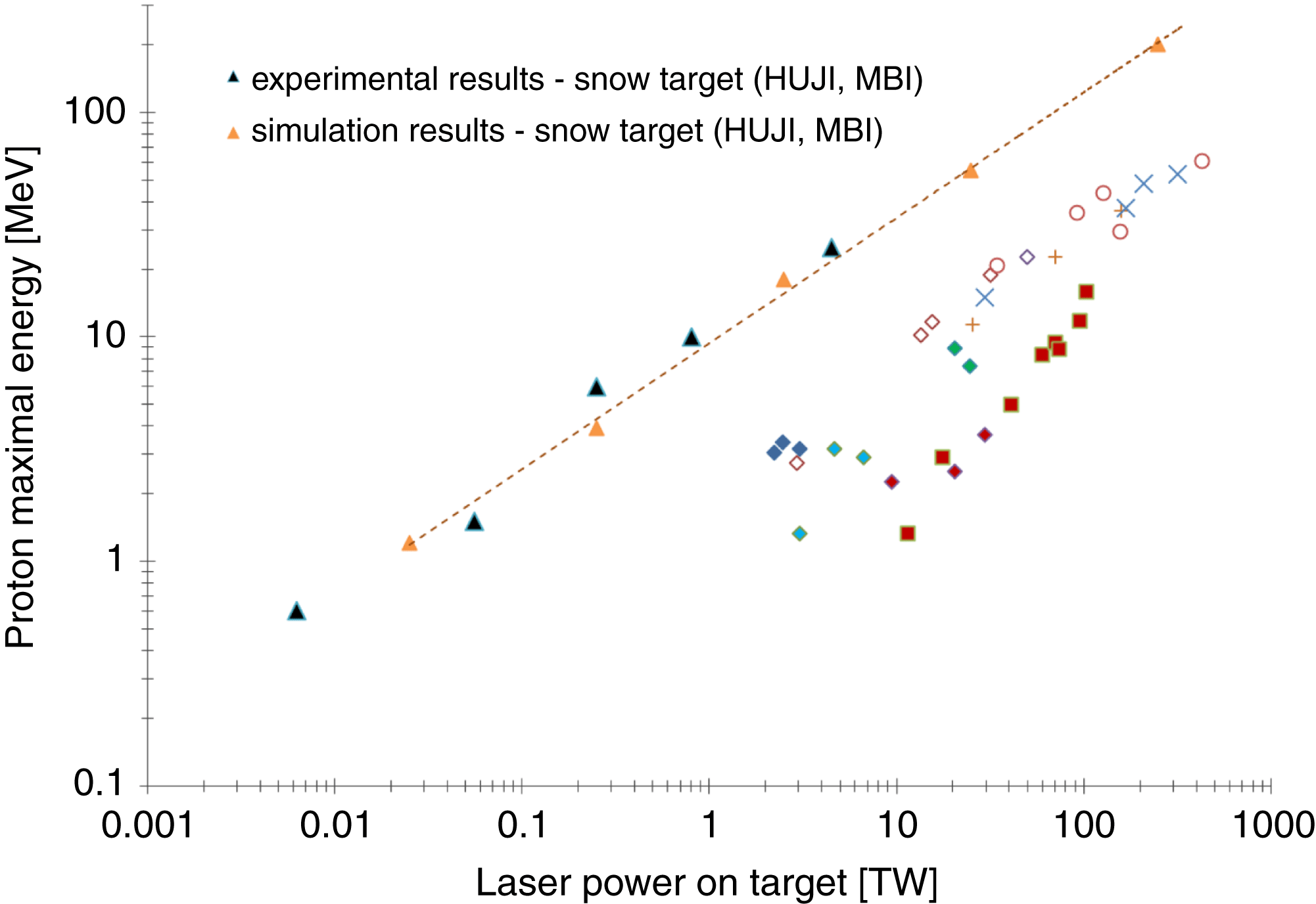
Figure 1. Proton maximal energy as a function of laser power the on target (triangles: snow target experimental and simulation results)[Reference Palchan, Henis, Faenov, Magunov, Pikuz, Gasilov, Skobelev and Zigler8–Reference Zigler, Eisenman, Botton, Nahum, Schleifer, Baspaly, Pomerantz, Abicht, Branzel, Priebe, Steinke, Andreev, Schnuerer, Sandner, Gordon, Sprangle and Ledingham10]; other shapes: different targets and laser facilities)[Reference Zeil, Kraft, Bock, Bussmann, Cowan, Kluge, Metzkes, Richter, Sauerbrey and Schramm11].

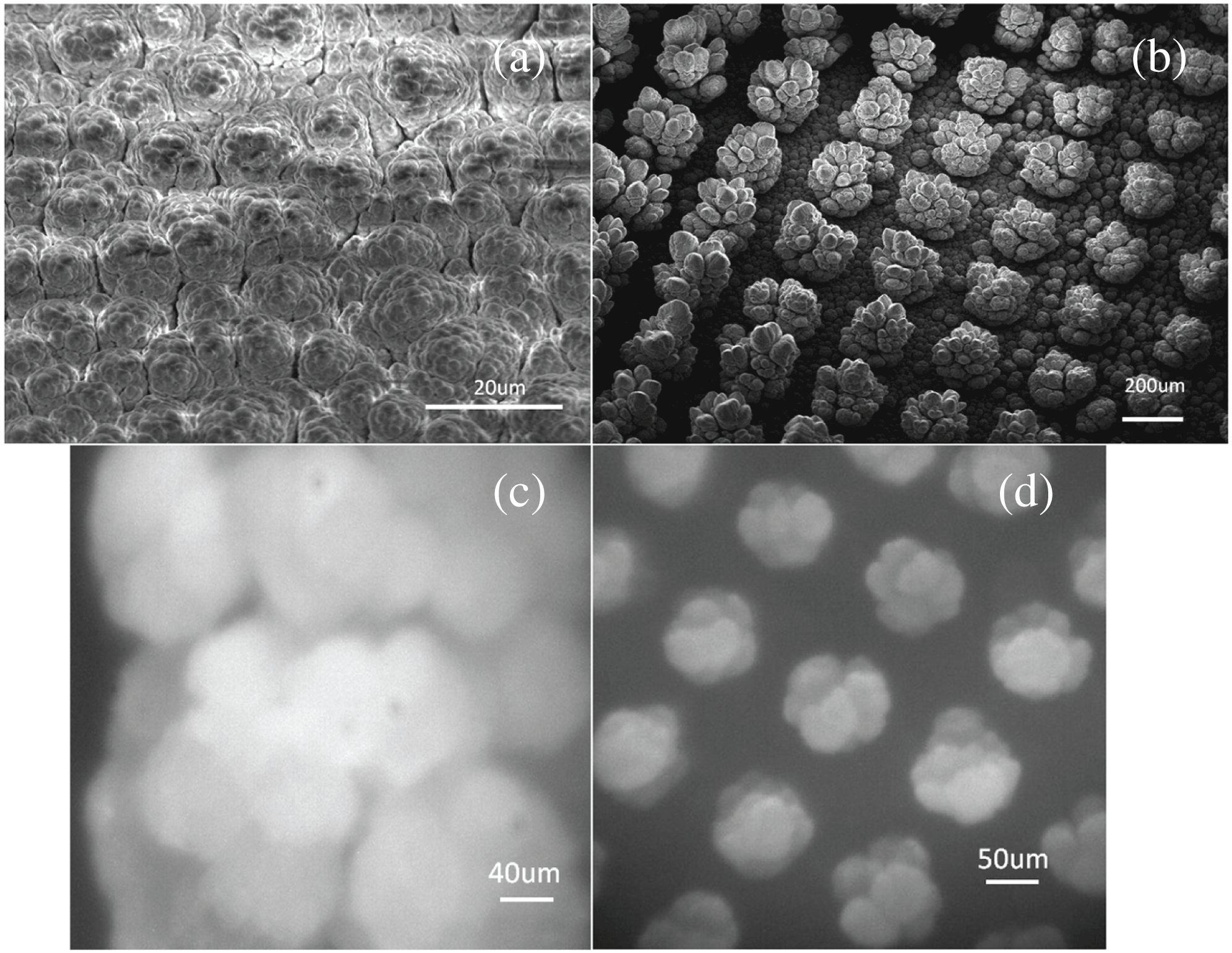
Figure 2. Snow morphology images. Images (a) and (c) are SEM and optical pictures of snow micro-columns without nucleation centers. Images (b) and (d) are SEM and optical pictures of snow micro-columns with nucleation centers.
Recently, we demonstrated that by using frozen ![]() ${\rm H}_{2}{\rm O}$ micro-column targets, which were grown on a sapphire substrate, significantly improved absorption of the laser energy by the
${\rm H}_{2}{\rm O}$ micro-column targets, which were grown on a sapphire substrate, significantly improved absorption of the laser energy by the ![]() ${\rm H}_{2}{\rm O}$ micro-column target took place. This study showed that more than 90% of the incident energy was absorbed by the target[Reference Plachan, Pecker, Henis, Eisenmann and Zigler7]. Moreover, we have shown that the emitted proton energy scales up by a factor of 10 compared with standard laser driven protons schemes[Reference Palchan, Henis, Faenov, Magunov, Pikuz, Gasilov, Skobelev and Zigler8–Reference Zeil, Kraft, Bock, Bussmann, Cowan, Kluge, Metzkes, Richter, Sauerbrey and Schramm11]. The maximal proton energy as a function of laser power is presented in Figure 1. Numerical particle in cell (PIC) simulations indicate that the enhancement of proton energy is attributed to the structure of the snow target and the pre-plasma formed by the pre-pulse and the density gradients formed[Reference Zigler, Eisenman, Botton, Nahum, Schleifer, Baspaly, Pomerantz, Abicht, Branzel, Priebe, Steinke, Andreev, Schnuerer, Sandner, Gordon, Sprangle and Ledingham10].
${\rm H}_{2}{\rm O}$ micro-column target took place. This study showed that more than 90% of the incident energy was absorbed by the target[Reference Plachan, Pecker, Henis, Eisenmann and Zigler7]. Moreover, we have shown that the emitted proton energy scales up by a factor of 10 compared with standard laser driven protons schemes[Reference Palchan, Henis, Faenov, Magunov, Pikuz, Gasilov, Skobelev and Zigler8–Reference Zeil, Kraft, Bock, Bussmann, Cowan, Kluge, Metzkes, Richter, Sauerbrey and Schramm11]. The maximal proton energy as a function of laser power is presented in Figure 1. Numerical particle in cell (PIC) simulations indicate that the enhancement of proton energy is attributed to the structure of the snow target and the pre-plasma formed by the pre-pulse and the density gradients formed[Reference Zigler, Eisenman, Botton, Nahum, Schleifer, Baspaly, Pomerantz, Abicht, Branzel, Priebe, Steinke, Andreev, Schnuerer, Sandner, Gordon, Sprangle and Ledingham10].
Characterization and control of the morphology of the micro-structured targets is necessary to gain a better understanding of the interaction process and for optimization of the proton acceleration. As a first step, we present here a method to control the position of the micro-columns which is based on seeding of nucleation centers on the sapphire substrate. The nucleation centers were implanted on the sapphire substrate by spattering of aluminum. The size and shape of the seeding dots were determined by laser writing lithography. Selective growth of the micro-columns on the nucleation centers was achieved. The obtained structured target is characterized by enhanced order of each micro-column. The detailed shape of the column is determined by the growth parameters, which will be described elsewhere. Scanning electron microscopy (SEM) and optical images of the structured target are shown in Figure 2. Figures 2(a) and (c) are of non-structured targets whereas Figures 2(b) and (d) are of the structured targets. The difference is self-evident.
Previous experiments and PIC simulations have shown the important role of the pre-plasma on the proton acceleration mechanism[Reference Zigler, Eisenman, Botton, Nahum, Schleifer, Baspaly, Pomerantz, Abicht, Branzel, Priebe, Steinke, Andreev, Schnuerer, Sandner, Gordon, Sprangle and Ledingham10]. In this paper we present a measurement of the mean plasma density for different time delays after the pre-pulse interacts with the target. This density measurement profile will be integrated into our PIC simulation and will allow us to better understand the acceleration mechanism. The structured targets were used to characterize the plasma generated by the laser pre-pulse. The pre-pulse originates from the regenerative amplifier, thus the pre-pulse comes 10 ns before the short main pulse. Both the pulse and the pre-pulse are 40 fs (FWHM) with better than 10![]() $^{-5}$ contrast up to 1 ps. In this case the plasma forms 10 ns before the main pulse and during this time the plasma can freely expand and a highly nonuniform plasma cloud is formed. By the time of its arrival, the main pulse meets this highly structured dynamic plasma cloud and interacts with it to produce the accelerated protons[Reference Zigler, Eisenman, Botton, Nahum, Schleifer, Baspaly, Pomerantz, Abicht, Branzel, Priebe, Steinke, Andreev, Schnuerer, Sandner, Gordon, Sprangle and Ledingham10]. The ordered structured targets enabled measurement of the electron density of the pre-plasma created by a pre-pulse. Due to the increased spacing between the columns, the laser beam interacts with only one of them each shot, hence the other columns do not block the optical path of the plasma formed by the interaction of the laser with the target. The plasma density was derived by spectroscopic measurements. It was calculated using the line broadening of the hydrogen due to the Stark effect[Reference Griem, Halenka and Olchawa12]. Regular interferometry and Thompson scattering could not be utilized due to the morphology of the target and the impossibility of perpendicular line of sight. The spectroscopic method gives a fairly good measurement of the mean density, but lacks in spatial resolution. The method presented here could realize the detection of the density profile for different times in usual target normal sheath acceleration (TNSA) experiments with the use of different spectroscopic line broadenings that were chosen for our experiment. The mean plasma electron density in our experiment was derived from the line broadening caused by the linear Stark effect in the Balmer hydrogen series at 656.28 nm. This line was chosen due to the richness of hydrogen in our target and the mean density expected in our experiment.
$^{-5}$ contrast up to 1 ps. In this case the plasma forms 10 ns before the main pulse and during this time the plasma can freely expand and a highly nonuniform plasma cloud is formed. By the time of its arrival, the main pulse meets this highly structured dynamic plasma cloud and interacts with it to produce the accelerated protons[Reference Zigler, Eisenman, Botton, Nahum, Schleifer, Baspaly, Pomerantz, Abicht, Branzel, Priebe, Steinke, Andreev, Schnuerer, Sandner, Gordon, Sprangle and Ledingham10]. The ordered structured targets enabled measurement of the electron density of the pre-plasma created by a pre-pulse. Due to the increased spacing between the columns, the laser beam interacts with only one of them each shot, hence the other columns do not block the optical path of the plasma formed by the interaction of the laser with the target. The plasma density was derived by spectroscopic measurements. It was calculated using the line broadening of the hydrogen due to the Stark effect[Reference Griem, Halenka and Olchawa12]. Regular interferometry and Thompson scattering could not be utilized due to the morphology of the target and the impossibility of perpendicular line of sight. The spectroscopic method gives a fairly good measurement of the mean density, but lacks in spatial resolution. The method presented here could realize the detection of the density profile for different times in usual target normal sheath acceleration (TNSA) experiments with the use of different spectroscopic line broadenings that were chosen for our experiment. The mean plasma electron density in our experiment was derived from the line broadening caused by the linear Stark effect in the Balmer hydrogen series at 656.28 nm. This line was chosen due to the richness of hydrogen in our target and the mean density expected in our experiment.

Figure 3. Schematics of the experimental setup.

Figure 4. Line broadening of hydrogen for different time delays between the pre-pulse and the main pulse: (a) ![]() $t = 10$ ns, (b)
$t = 10$ ns, (b) ![]() $t = 40$ ns, (c)
$t = 40$ ns, (c) ![]() $t = 90$ ns.
$t = 90$ ns.
The experiments were performed at the Hebrew University High Intensity Laser facility (HUJI). A schematic representation of the experimental setup is shown in Figure 3. The laser used for the experiments was a chirped pulse amplification Ti:sapphire laser, which delivered a 20 mJ in 40 fs (FWHM) pulse at a central wavelength of 800 nm with 10 Hz repetition rate. The intensity contrast ratio between the main laser pulse and the pre-pulse was ![]() $10^{-3}$ and the time difference was 10 ns; both pulses had less than
$10^{-3}$ and the time difference was 10 ns; both pulses had less than ![]() $10^{-5}$ pedestal up to 1 ps before the corresponding pulse as measured by a combination of a fast photodiode and oscilloscope. The laser beam was focused using an off-axis parabola having an
$10^{-5}$ pedestal up to 1 ps before the corresponding pulse as measured by a combination of a fast photodiode and oscilloscope. The laser beam was focused using an off-axis parabola having an ![]() $F$ value of 3.3 with an incident angle of
$F$ value of 3.3 with an incident angle of ![]() $60^{\circ }$ to the target surface normal. A deformable mirror was used to overcome the deformations in the wave front, and in order to reach a focal spot area (FWHM) of 100
$60^{\circ }$ to the target surface normal. A deformable mirror was used to overcome the deformations in the wave front, and in order to reach a focal spot area (FWHM) of 100 ![]() $\mu {\rm m}^{2}$, reaching an estimated intensity of
$\mu {\rm m}^{2}$, reaching an estimated intensity of ![]() $5\times {10}^{17}\ \mathrm{W\ cm}^{-2}$ in the main pulse. In order to reproduce the same conditions as the interaction of the pre-pulse with the target, a filter with an optical density (OD) of 3 was used on the main beam. The radiation emitted by the plasma was collected using a lens and was imaged into a spectrometer entrance slit (0.3 m optical length, 1800 lines/mm grating) coupled to a fast gated ICCD. The gating was varied between 10 and 90 ns to within a few ns jitter with respect to the ablating laser. The spectral resolution was calibrated using the doublet of sodium at 589.59 nm and was better than 3 Å.
$5\times {10}^{17}\ \mathrm{W\ cm}^{-2}$ in the main pulse. In order to reproduce the same conditions as the interaction of the pre-pulse with the target, a filter with an optical density (OD) of 3 was used on the main beam. The radiation emitted by the plasma was collected using a lens and was imaged into a spectrometer entrance slit (0.3 m optical length, 1800 lines/mm grating) coupled to a fast gated ICCD. The gating was varied between 10 and 90 ns to within a few ns jitter with respect to the ablating laser. The spectral resolution was calibrated using the doublet of sodium at 589.59 nm and was better than 3 Å.
In Figure 4 we present the broadening of the hydrogen line (at 656.28 nm) for different time delays corresponding to the ablating laser.
The mean electron density was calculated using[Reference Griem, Halenka and Olchawa12]
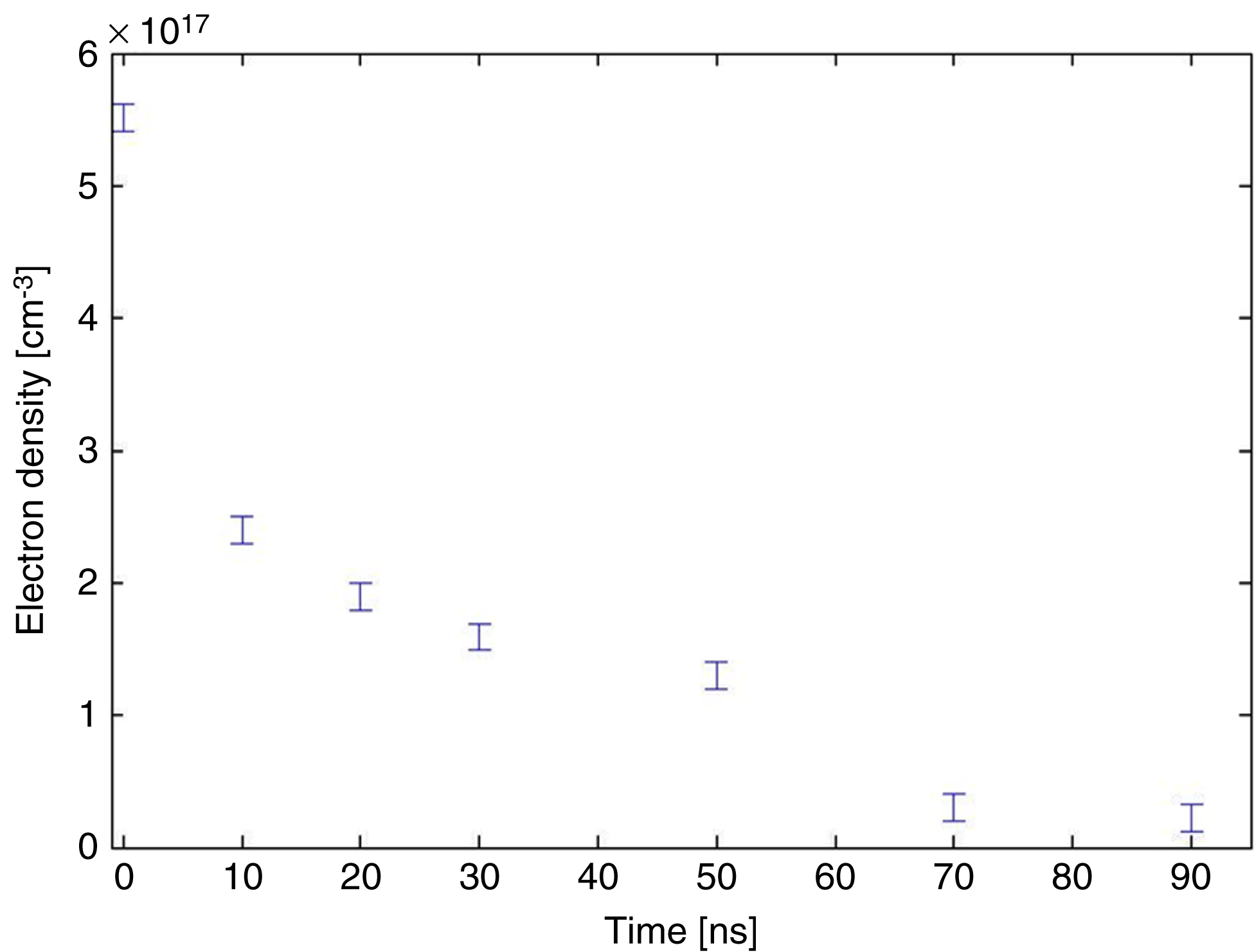
The mean electron density is presented as a function of the delay in Figure 5. It was found that the mean electron density of the pre-plasma after 10 ns was ![]() $N_{e} \cong 2\times 10^{17}\ \mathrm{cm}^{-3}$. This mean density is the pre-plasma density which our main pulse is interacting with.
$N_{e} \cong 2\times 10^{17}\ \mathrm{cm}^{-3}$. This mean density is the pre-plasma density which our main pulse is interacting with.

Figure 5. Mean electron density as a function of the delay after the interaction of the pre-pulse with the snow target.
Although the mean density agrees with our estimates, a better spatial description of the plasma cloud is sought. We are currently in the process of developing a system in which spatial measurements of the plasma cloud can be measured. It should be noted that these measurements are not trivial as the average density is low but the gradients are not. This measurement will contribute to a better understanding of the interaction of a high intensity laser with our targets. The spatial electron density measured will be integrated into our PIC code and will allow a better understanding of the acceleration mechanism.
In conclusion, we have achieved the manufacture of ordered snow micro-column targets using nucleation sites deposited on a sapphire substrate. This target allowed the measurement of the plasma density generated by the pre-pulse for different time delays after the interaction between the pre-pulse and the snow column target. This research will allow a better understanding of the generation of fast protons from the interaction between structured pre-plasma and high intensity lasers.


