1 Introduction
Burst-mode picosecond green lasers with a high pulse energy and high average power have important applications in many fields. One of the most promising applications is space debris laser ranging[Reference Kirchner, Koidl, Friederich, Buske, Völker and Riede1, Reference Zhang, Zhang, Long, Deng, Wu and Meng2]. Monitoring and early warning of space debris have attracted considerable attention worldwide owing to a dramatic increase in space garbage, which poses a serious threat to spacecraft operation and human space activities. Moreover, space debris laser ranging technology not only enables real-time space debris orbit measurement with high precision (one or two orders of magnitude higher than that of other ground-based observation equipment) but also provides calibration for other monitoring methods. Nanosecond lasers are currently used as the light source for space debris laser ranging because they are readily available at higher pulse energies than picosecond lasers. However, the use of lasers with picosecond pulses can afford improved ranging precision owing to their narrow pulse duration; in addition, their pulses are longer than femtosecond pulses, enabling the detector to respond. Because the laser beam is diffusely reflected by space debris, however, a higher laser pulse energy is needed for the detector to capture the reflected photons. As the pulse energy increases, smaller and more distant space debris can be measured, and raising the repetition rate of the laser shortens the time interval between adjacent diffusely reflected pulses, improving the speed of target acquisition. A recent study[Reference Zhang, Zhang, Long, Deng, Wu and Meng2] showed that using a double-pulse picosecond laser for tracking space debris increases the ranging precision of laser space debris measurement from the decimeter level to the centimeter level. Besides, burst-mode lasers also have advantages in the fields of fine machining application[Reference Kerse, Kalaycioglu, Elahi, Cetin, Kesim, Akcaalan, Yavas, Asik, Oktem, Hoogland, Holzwarth and Ilday3] and scientific research[Reference Gao, Long and Meng4].
Various methods have been proposed to obtain high-pulse-energy and high-average-power ultrashort green lasers for high-energy ultrafast laser systems; these include beam shaping techniques[Reference Hoffnagle and Jefferson5], chirped-pulse amplification (CPA)[Reference Long, Chen, Chen and Li6], beam combining[Reference Želudevičius, Regelskis and Račiukaitis7] and nonlinear interactions[Reference Yuan, Wang, Yuan, Hu, Cui, Liu, Li, Chen, Jing and Lu8], which can all maximize the pulse energy extraction and reduce the damage threshold requirement of subsequent optical components. In 2013, Noom et al. [Reference Noom, Witte, Morgenweg, Altmann and Eikema9] reported a laser amplification system with a top-hat intensity profile that produces 130 mJ, 64 ps pulses at 1064 nm; after frequency doubling, 75 mJ, 64 ps pulses were obtained at 532 nm with a repetition rate of 300 Hz and a conversion efficiency of 50%. However, the beam shaping efficiency was less than 1% (a pulse energy output of only 0.07 mJ for a 1.2 mJ input). In 2016, Adamonis et al. [Reference Adamonis, Aleknavicius, Michailovas, Balickas, Petrauskiene, Gertus and Michailovas10] used a spatially variable wave plate for beam shaping, which reshaped the seed beam into a 12th-order super-Gaussian beam with an efficiency of approximately 50%; the output beam power in both channels was 130 W at 1064 nm. Further, using noncollinear frequency up-conversion in a lithium triborate (LBO) crystal, they obtained 150 mJ, 85 ps green light at a repetition rate of 1 kHz. The conversion efficiency was approximately 58%.
CPA technology is used mainly in femtosecond laser systems, where a broader linewidth in the gain medium is useful[Reference Wang, Liu, Shen, Zhang, Teng and Wei11, Reference Strickland and Mourou12]. Pulse duration broadening to the picosecond level is also a somewhat effective way to avoid optical damage and obtain a high average power without increasing the number of optical components, although the spectral linewidth of picosecond pulses, which is narrower than that of femtosecond pulses, limits their broadening efficiency. In 2017, Long et al. [Reference Long, Li and Chen13] reported that a laser pulse duration of 23.5 ps was broadened to 115 ps by a volume Bragg grating (VBG), and, after two-stage Nd:YAG traveling-wave amplification, the laser exhibited an average power of 96 W at 1064 nm.
Beam combining, including coherent beam combining and spectral beam combining, is another way to obtain high-power lasers. To realize a high peak power using fiber amplifiers, in 2017, Želudevičius et al. [Reference Želudevičius, Regelskis and Račiukaitis7] obtained an overall conversion efficiency of 51% and an average power of 29 W at 532 nm with a pulse duration of ![]() ${\sim}200~\text{ps}$ using pulse multiplexing and beam combining of four pulsed Yb-doped fiber lasers by noncollinear frequency up-conversion in an LBO crystal.
${\sim}200~\text{ps}$ using pulse multiplexing and beam combining of four pulsed Yb-doped fiber lasers by noncollinear frequency up-conversion in an LBO crystal.
In this study, we designed a high-pulse-energy, high-average-power burst-mode picosecond laser system for space debris laser ranging. It consists of a semiconductor saturable absorber mirror (SESAM) mode-locked picosecond oscillator, VBG pulse stretcher, pulse splitting system designed to obtain a nanosecond pulse interval in the burst, a burst-mode regenerative amplifier (RA) and a ring pattern beam reshaping system consisting of two aspheric lenses, two-stage power amplifiers and a high-efficiency frequency doubler. Moreover, it adopts the collinear output of the fundamental beam and second harmonic generation (SHG), and both frequency pulses can be used simultaneously for space debris laser ranging to improve the measurement accuracy or operated independently. In particular, the fundamental beam, which can operate during the day, reduces the effect of the sun. Further, the relative amplitude of each pulse in the burst, as well as the pulse interval, can be easily adjusted, which is convenient for experimental research on space debris ranging. The aspheric lens system reshapes the Gaussian beam output by the RA to a ring profile with high conversion efficiency, which reduces the difficulty of subsequent amplification; consequently, an average power of up to 50 W at 532 nm is obtained, which corresponds to a pulse envelope energy of 50 mJ, and the second harmonic conversion efficiency reaches 68%.
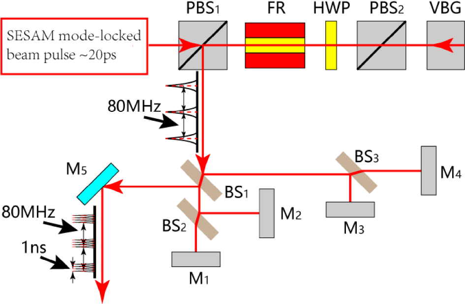
Figure 1. Schematic diagram of the seed laser. ![]() $\text{PBS}_{1}$,
$\text{PBS}_{1}$, ![]() $\text{PBS}_{2}$: polarization beam splitters; FR: Faraday rotator isolator; HWP: half-wave plate; VBG: volume Bragg grating;
$\text{PBS}_{2}$: polarization beam splitters; FR: Faraday rotator isolator; HWP: half-wave plate; VBG: volume Bragg grating; ![]() $\text{BS}_{1}{-}\text{BS}_{3}$: beam splitters;
$\text{BS}_{1}{-}\text{BS}_{3}$: beam splitters; ![]() $\text{M}_{1}{-}\text{M}_{5}$: high-reflectivity mirrors.
$\text{M}_{1}{-}\text{M}_{5}$: high-reflectivity mirrors.
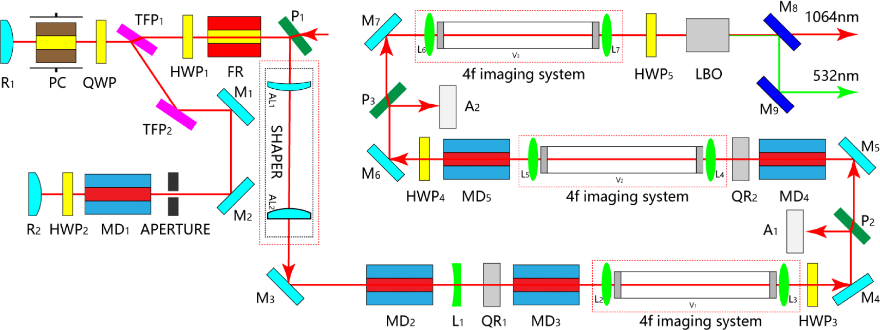
Figure 2. Schematic diagram of the amplifier and SHG construction. ![]() $\text{P}_{1}{-}\text{P}_{3}$: polarizers; FR: Faraday rotator isolator;
$\text{P}_{1}{-}\text{P}_{3}$: polarizers; FR: Faraday rotator isolator; ![]() $\text{HWP}_{1}{-}\text{HWP}_{5}$: half-wave plates;
$\text{HWP}_{1}{-}\text{HWP}_{5}$: half-wave plates; ![]() $\text{TFP}_{1}$,
$\text{TFP}_{1}$, ![]() $\text{TFP}_{2}$: thin-film polarizers; QWP: quarter-wave plate; PC: Pockels cell;
$\text{TFP}_{2}$: thin-film polarizers; QWP: quarter-wave plate; PC: Pockels cell; ![]() $\text{R}_{1}$,
$\text{R}_{1}$, ![]() $\text{R}_{2}$: convex mirrors;
$\text{R}_{2}$: convex mirrors; ![]() $\text{M}_{1}{-}\text{M}_{7}$: high-reflectivity mirrors;
$\text{M}_{1}{-}\text{M}_{7}$: high-reflectivity mirrors; ![]() $\text{MD}_{1}{-}\text{MD}_{5}$: Nd:YAG modules;
$\text{MD}_{1}{-}\text{MD}_{5}$: Nd:YAG modules; ![]() $\text{AL}_{1}$,
$\text{AL}_{1}$, ![]() $\text{AL}_{2}$: aspheric lenses;
$\text{AL}_{2}$: aspheric lenses; ![]() $\text{L}_{1}{-}\text{L}_{7}$: lenses;
$\text{L}_{1}{-}\text{L}_{7}$: lenses; ![]() $\text{V}_{1}{-}\text{V}_{3}$: vacuum tubes;
$\text{V}_{1}{-}\text{V}_{3}$: vacuum tubes; ![]() $\text{QR}_{1}$,
$\text{QR}_{1}$, ![]() $\text{QR}_{2}$:
$\text{QR}_{2}$: ![]() $90^{\circ }$ quartz rotators;
$90^{\circ }$ quartz rotators; ![]() $\text{A}_{1}$,
$\text{A}_{1}$, ![]() $\text{A}_{2}$: aluminum blocks;
$\text{A}_{2}$: aluminum blocks; ![]() $\text{M}_{8}$,
$\text{M}_{8}$, ![]() $\text{M}_{9}$: dichroic mirrors.
$\text{M}_{9}$: dichroic mirrors.
2 Experimental setup
The seed laser, which is shown schematically in Figure 1, consists of a home-built ![]() $\text{Nd}:\text{YVO}_{4}$ SESAM mode-locked laser with a repetition rate of 80 MHz and a pulse duration of
$\text{Nd}:\text{YVO}_{4}$ SESAM mode-locked laser with a repetition rate of 80 MHz and a pulse duration of ![]() ${\sim}20~\text{ps}$, a Faraday isolator that protects the oscillator from potential feedback from subsequent components, a pulse stretcher and a burst-mode setup. In the single-pass pulse stretcher, a VBG with a modulation coefficient of
${\sim}20~\text{ps}$, a Faraday isolator that protects the oscillator from potential feedback from subsequent components, a pulse stretcher and a burst-mode setup. In the single-pass pulse stretcher, a VBG with a modulation coefficient of ![]() $550~\text{ps}/\text{nm}$ is used. After the beam travels through the VBG (
$550~\text{ps}/\text{nm}$ is used. After the beam travels through the VBG (![]() $4~\text{mm}\times 4~\text{mm}\times 18~\text{mm}$), the pulse duration of the seed laser is broadened to
$4~\text{mm}\times 4~\text{mm}\times 18~\text{mm}$), the pulse duration of the seed laser is broadened to ![]() ${\sim}100~\text{ps}$, and the power decreases to 878 mW, which corresponds to a diffraction efficiency of 80%. Four pulses per burst are obtained using an improved Michelson interferometer. BS1, BS2 and BS3 are beam splitters with 50:50 beam splitting at a
${\sim}100~\text{ps}$, and the power decreases to 878 mW, which corresponds to a diffraction efficiency of 80%. Four pulses per burst are obtained using an improved Michelson interferometer. BS1, BS2 and BS3 are beam splitters with 50:50 beam splitting at a ![]() $45^{\circ }$ incidence angle. By choosing appropriate length intervals between mirrors M2–M5, which gradually increase by equal increments (
$45^{\circ }$ incidence angle. By choosing appropriate length intervals between mirrors M2–M5, which gradually increase by equal increments (![]() $\unicode[STIX]{x0394}L$), we can obtain pulses in bursts with equal time delays of
$\unicode[STIX]{x0394}L$), we can obtain pulses in bursts with equal time delays of ![]() $\unicode[STIX]{x0394}t$. To meet the requirements for space debris measurement and accommodate the high-voltage operation time of a Pockels cell (PC; which operates as a pulse selection switch) in the RA, a time delay of
$\unicode[STIX]{x0394}t$. To meet the requirements for space debris measurement and accommodate the high-voltage operation time of a Pockels cell (PC; which operates as a pulse selection switch) in the RA, a time delay of ![]() ${\sim}1~\text{ns}$ (
${\sim}1~\text{ns}$ (![]() $\unicode[STIX]{x0394}t=2\times \unicode[STIX]{x0394}L/c$, where
$\unicode[STIX]{x0394}t=2\times \unicode[STIX]{x0394}L/c$, where ![]() $c$ is the speed of light) is obtained by setting
$c$ is the speed of light) is obtained by setting ![]() $\unicode[STIX]{x0394}L=150~\text{mm}$.
$\unicode[STIX]{x0394}L=150~\text{mm}$.
To realize high-power, high-energy picosecond pulsed lasers, a diode-side-pumped Nd:YAG RA and a two-stage traveling-wave amplification are adopted for the amplifier system, as shown in Figure 2. The Nd:YAG RA, which acts as a pre-amplifier, reduces the repetition rate of the seed laser from 80 MHz to 1 kHz by electro-optic modulation. The seed laser is injected into the RA through the optical isolation system from ![]() $\text{P}_{1}$ and then output from
$\text{P}_{1}$ and then output from ![]() $\text{P}_{1}$ after amplification. And the FR and HWP1 act as an optical isolation system to avoid the influence of the output amplified beam returning to the seed oscillation cavity on the seed optical stability. The quarter-wave plate (QWP) and PC constitute the pulse selected switch in the RA. The pumping module
$\text{P}_{1}$ after amplification. And the FR and HWP1 act as an optical isolation system to avoid the influence of the output amplified beam returning to the seed oscillation cavity on the seed optical stability. The quarter-wave plate (QWP) and PC constitute the pulse selected switch in the RA. The pumping module ![]() $(\text{MD}_{1})$ has a central wavelength of 808 nm with a repetition rate of 1 kHz. The dimension of the Nd:YAG crystal rod is
$(\text{MD}_{1})$ has a central wavelength of 808 nm with a repetition rate of 1 kHz. The dimension of the Nd:YAG crystal rod is ![]() $\unicode[STIX]{x1D6F7}\;4~\text{mm}\times 67~\text{mm}$ with 1 at.% doped. Then, the Gaussian output beam of the RA is converted into a ring-shaped beam using an aspheric lens reshaping system with a conversion efficiency of approximately 93%. The total length of the shaping system we used is 90 mm, which is a typical Galilean configuration (without internal focusing), consisting of two aspheric lenses. The front surface of the first lens is concave to ensure that no rays cross the optical axis and the back surface is aspheric; the second lens has an aspheric–planar structure. The apertures of two aspheric lenses are 8 mm and 15 mm, respectively, and both sides of the lenses are coated with an anti-reflection film of 1064 nm. The purpose of shaping is to reduce the central light intensity of the spot and avoid self-focusing during amplification. To maintain the beam quality during the two-stage single-pass double-module amplification, two 4f imaging systems are used, and all the subsequent imaging systems contain vacuum tubes to prevent air breakdown. The laser-diode-pumped bars of two modules in each stage are arranged at complementary angles to reduce the depolarization loss. The same as
$\unicode[STIX]{x1D6F7}\;4~\text{mm}\times 67~\text{mm}$ with 1 at.% doped. Then, the Gaussian output beam of the RA is converted into a ring-shaped beam using an aspheric lens reshaping system with a conversion efficiency of approximately 93%. The total length of the shaping system we used is 90 mm, which is a typical Galilean configuration (without internal focusing), consisting of two aspheric lenses. The front surface of the first lens is concave to ensure that no rays cross the optical axis and the back surface is aspheric; the second lens has an aspheric–planar structure. The apertures of two aspheric lenses are 8 mm and 15 mm, respectively, and both sides of the lenses are coated with an anti-reflection film of 1064 nm. The purpose of shaping is to reduce the central light intensity of the spot and avoid self-focusing during amplification. To maintain the beam quality during the two-stage single-pass double-module amplification, two 4f imaging systems are used, and all the subsequent imaging systems contain vacuum tubes to prevent air breakdown. The laser-diode-pumped bars of two modules in each stage are arranged at complementary angles to reduce the depolarization loss. The same as ![]() $\text{MD}_{1}$, all of the pumping modules used in the power amplifiers have a central wavelength of 808 nm with a repetition rate of 1 kHz. Two modules in each stage are powered by the same power supply and cooled by the same waterway, and the cooling water temperature is set to
$\text{MD}_{1}$, all of the pumping modules used in the power amplifiers have a central wavelength of 808 nm with a repetition rate of 1 kHz. Two modules in each stage are powered by the same power supply and cooled by the same waterway, and the cooling water temperature is set to ![]() $25^{\circ }$. The dimension of the Nd:YAG crystal rods used in the first-stage pumping modules is
$25^{\circ }$. The dimension of the Nd:YAG crystal rods used in the first-stage pumping modules is ![]() $\unicode[STIX]{x1D6F7}\;4~\text{mm}\times 67~\text{mm}$ with 1 at.% doped. In the second-stage modules, the dimension of the crystal rods is
$\unicode[STIX]{x1D6F7}\;4~\text{mm}\times 67~\text{mm}$ with 1 at.% doped. In the second-stage modules, the dimension of the crystal rods is ![]() $\unicode[STIX]{x1D6F7}\;6~\text{mm}\times 85~\text{mm}$ with 0.8 at.% doped. A half-wave plate and
$\unicode[STIX]{x1D6F7}\;6~\text{mm}\times 85~\text{mm}$ with 0.8 at.% doped. A half-wave plate and ![]() $90^{\circ }$ quartz rotator help to compensate for the difference in optical power between the tangential and radial polarization components of the thermal lens. To improve the degree of polarization, two
$90^{\circ }$ quartz rotator help to compensate for the difference in optical power between the tangential and radial polarization components of the thermal lens. To improve the degree of polarization, two ![]() $45^{\circ }$ polarizers are used to remove the vertically polarized light added during amplification.
$45^{\circ }$ polarizers are used to remove the vertically polarized light added during amplification. ![]() $\text{L}_{1}$ is a plane concave lens used to compensate for the thermal lens, and all of the amplifier modules are synchronized between the seed and pump pulses with a pump pulse width of
$\text{L}_{1}$ is a plane concave lens used to compensate for the thermal lens, and all of the amplifier modules are synchronized between the seed and pump pulses with a pump pulse width of ![]() $200~\unicode[STIX]{x03BC}\text{s}$.
$200~\unicode[STIX]{x03BC}\text{s}$.

Figure 3. Waveform of RA.
The frequency conversion module, which is used to adjust the beam size and divergence, is placed behind the 4f imaging system to realize the highest conversion efficiency. To further improve the conversion efficiency, a thin-film polarizer at 1064 nm is used to purify the polarization direction of the amplified fundamental light. The second harmonic waves are generated by an LBO crystal (![]() $6~\text{mm}\times 6~\text{mm}\times 15~\text{mm}$), which was chosen for its excellent performance: a high damage threshold, relatively high nonlinearity, a large acceptance angle and no spatial walk-off for type-I noncritical phase matching at 1064 nm. The crystal is combined with a half-wave plate to obtain the best phase-matching condition. The LBO crystal is placed in an oven at
$6~\text{mm}\times 6~\text{mm}\times 15~\text{mm}$), which was chosen for its excellent performance: a high damage threshold, relatively high nonlinearity, a large acceptance angle and no spatial walk-off for type-I noncritical phase matching at 1064 nm. The crystal is combined with a half-wave plate to obtain the best phase-matching condition. The LBO crystal is placed in an oven at ![]() $149\,^{\circ }\text{C}$ with a control accuracy of
$149\,^{\circ }\text{C}$ with a control accuracy of ![]() $\pm 0.05\,^{\circ }\text{C}$. To measure the efficiency of light frequency doubling, two dichroic mirrors with
$\pm 0.05\,^{\circ }\text{C}$. To measure the efficiency of light frequency doubling, two dichroic mirrors with ![]() $45^{\circ }$ incidence are employed to separate the fundamental wave at 1064 nm and the second harmonic wave at 532 nm.
$45^{\circ }$ incidence are employed to separate the fundamental wave at 1064 nm and the second harmonic wave at 532 nm.
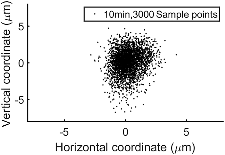
Figure 4. Beam direction fluctuation.
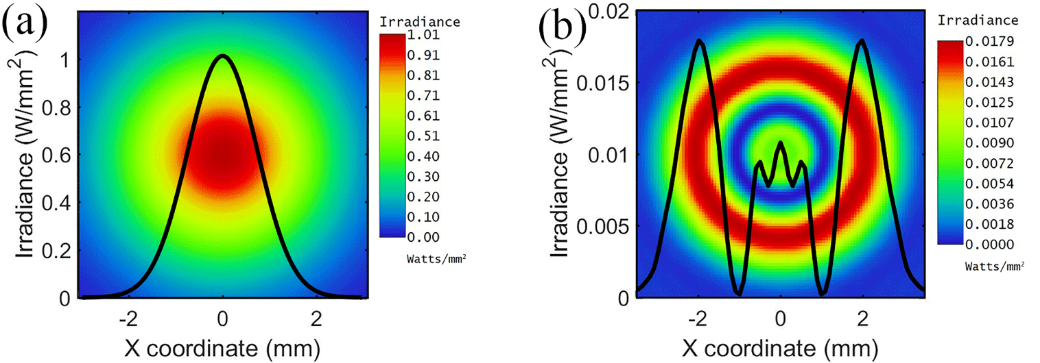
Figure 5. Intensity distributions of (a) input Gaussian beam (![]() $\text{TEM}_{00}$ laser) and (b) laser after the shaping lens.
$\text{TEM}_{00}$ laser) and (b) laser after the shaping lens.
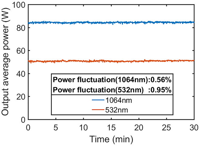
Figure 6. Power fluctuation at 1064 and 532 nm.
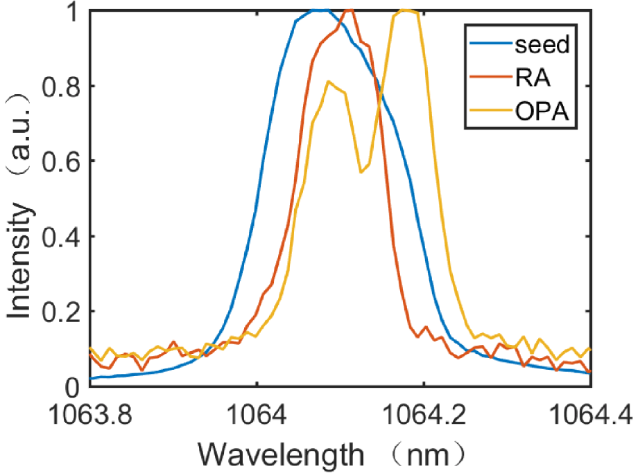
Figure 7. Spectral evolution of the system. The spectral widths of the seed, RA and oscillator power amplifier are 0.187, 0.112 and 0.142 nm, respectively.
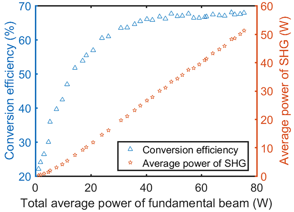
Figure 8. Dependence of the green power and second harmonic conversion efficiency on the incident fundamental power.
3 Experimental results
Owing to the properties of the RA[Reference Murray and Lowdermilk14, Reference Grishin, Gulbinas and Michailovas15], the coupling efficiency between the injected beam field and the regenerative cavity affects only the output beam intensity, not the beam direction; therefore, we can adjust the relative amplitude of each pulse in the bursts without affecting the collinearity of each sub-pulse by fine-tuning the mirrors behind the splitters, which changes the coupling efficiency of each sub-pulse injected into the regenerative cavity. In the waveform in Figure 3, the first pulse in the burst has a higher amplitude than the following three pulses, which have equal amplitudes. Note that we can also produce multiple pulses within each burst with the equivalent amplitude to satisfy different applications[Reference Long, Li and Chen13]. When the average pump power is set to 105 W at 808 nm, the average output power reaches 9 W after 25 extraction cycles in the regenerative amplifying cavity, and the beam diameter is ![]() ${\sim}1.5~\text{mm}$. Figure 4 shows the fluctuation of the direction of the beam output from the RA, which is less than
${\sim}1.5~\text{mm}$. Figure 4 shows the fluctuation of the direction of the beam output from the RA, which is less than ![]() $\pm 25~\unicode[STIX]{x03BC}\text{rad}$, as measured by a convex lens with a focal length of 200 mm and a camera with pixel dimensions of
$\pm 25~\unicode[STIX]{x03BC}\text{rad}$, as measured by a convex lens with a focal length of 200 mm and a camera with pixel dimensions of ![]() $5.5~\unicode[STIX]{x03BC}\text{m}\times 5.5~\unicode[STIX]{x03BC}\text{m}$. The beam from the RA is Gaussian, and its shape is optimized by a Galilean beam expander system composed of two aspheric lenses. The first lens redistributes the intensity of the Gaussian beam, and the second lens collimates the beam. After passing through the shaping system, the beam has a ring-shaped profile without a strong central intensity distribution, as shown in Figure 5. After the first-stage amplifier (the total average pump power of two side-pump Nd:YAG modules is 605 W at 808 nm), the 8.4 W power is amplified to 31.4 W. Through
$5.5~\unicode[STIX]{x03BC}\text{m}\times 5.5~\unicode[STIX]{x03BC}\text{m}$. The beam from the RA is Gaussian, and its shape is optimized by a Galilean beam expander system composed of two aspheric lenses. The first lens redistributes the intensity of the Gaussian beam, and the second lens collimates the beam. After passing through the shaping system, the beam has a ring-shaped profile without a strong central intensity distribution, as shown in Figure 5. After the first-stage amplifier (the total average pump power of two side-pump Nd:YAG modules is 605 W at 808 nm), the 8.4 W power is amplified to 31.4 W. Through ![]() $\text{HWP}_{3}$ and
$\text{HWP}_{3}$ and ![]() $\text{P}_{2}$, the power reduces to 28.9 W, corresponding to the depolarization rate of 8.0%. Through the second-stage amplifier, the depolarization rate is 7.8%. The lower depolarization rate of the second-stage amplifier is due to the use of an array of five symmetrical laser-diode-pumped bars as pumping modules, which makes the thermal load distribution in the Nd:YAG rod more uniform, while the modules (
$\text{P}_{2}$, the power reduces to 28.9 W, corresponding to the depolarization rate of 8.0%. Through the second-stage amplifier, the depolarization rate is 7.8%. The lower depolarization rate of the second-stage amplifier is due to the use of an array of five symmetrical laser-diode-pumped bars as pumping modules, which makes the thermal load distribution in the Nd:YAG rod more uniform, while the modules (![]() $\text{MD}_{2}$,
$\text{MD}_{2}$, ![]() $\text{MD}_{3}$) used in the first-stage amplifier are three symmetrical laser-diode-pumped bars. After the amplifier system (the total average pump power of
$\text{MD}_{3}$) used in the first-stage amplifier are three symmetrical laser-diode-pumped bars. After the amplifier system (the total average pump power of ![]() $\text{MD}_{4}$ and
$\text{MD}_{4}$ and ![]() $\text{MD}_{5}$ increases to 1036 W at 808 nm), an average power of more than 80 W with a 0.56% power fluctuation over 30 min (Figure 6) is obtained at a repetition rate of 1 kHz, and the beam diameter is
$\text{MD}_{5}$ increases to 1036 W at 808 nm), an average power of more than 80 W with a 0.56% power fluctuation over 30 min (Figure 6) is obtained at a repetition rate of 1 kHz, and the beam diameter is ![]() ${\sim}5.5~\text{mm}$.
${\sim}5.5~\text{mm}$.
Figure 7 shows the spectral evolution of the system from narrowing to broadening. Specifically, the dominant peak of the spectrum after the RA narrows from 0.187 to 0.112 nm and is slightly red-shifted. The main reason for the central wavelength shift is the use of two different gain media. The gain medium in seed laser cavity is Nd:YVO![]() $_{4}$, while the gain medium used in the RA is Nd:YAG. However, the subsequent traveling-wave amplification causes spectral broadening with a two-peak structure. The physical mechanism of the spectral red shift and distortion is the self-phase modulation caused by gain saturation[Reference Penzkofer and Weinhardt16, Reference Agrawal and Olsson17].
$_{4}$, while the gain medium used in the RA is Nd:YAG. However, the subsequent traveling-wave amplification causes spectral broadening with a two-peak structure. The physical mechanism of the spectral red shift and distortion is the self-phase modulation caused by gain saturation[Reference Penzkofer and Weinhardt16, Reference Agrawal and Olsson17].
Frequency doubling is performed by controlling the fundamental beam with a small divergence angle into a 15-mm-long LBO at ![]() $90^{\circ }$ incidence. The size of the fundamental beam is no less than 5 mm, and the pulse peak intensity is as high as
$90^{\circ }$ incidence. The size of the fundamental beam is no less than 5 mm, and the pulse peak intensity is as high as ![]() $2~\text{GW}/\text{cm}^{2}$ but less than the damage threshold of the LBO. Figure 8 plots the dependence of the green power and second harmonic conversion efficiency on the incident fundamental power. The conversion efficiency increases monotonously with increasing incident power and reaches a maximum value of 68% at 40 W. Then, it fluctuates around 66% by 2%. By increasing the infrared power, we obtained green light with a power of up to 50 W and a power fluctuation of less than 1%, as shown in Figure 6. Similar to that of the amplified pulse, the spectrum of the green light has an asymmetric shape with a full-width at half-maximum of 64 pm, as shown in Figure 9. Figure 10 shows that the intensity distribution profile and beam quality factors of the green laser were
$2~\text{GW}/\text{cm}^{2}$ but less than the damage threshold of the LBO. Figure 8 plots the dependence of the green power and second harmonic conversion efficiency on the incident fundamental power. The conversion efficiency increases monotonously with increasing incident power and reaches a maximum value of 68% at 40 W. Then, it fluctuates around 66% by 2%. By increasing the infrared power, we obtained green light with a power of up to 50 W and a power fluctuation of less than 1%, as shown in Figure 6. Similar to that of the amplified pulse, the spectrum of the green light has an asymmetric shape with a full-width at half-maximum of 64 pm, as shown in Figure 9. Figure 10 shows that the intensity distribution profile and beam quality factors of the green laser were ![]() $M_{x}^{2}=3.358$ in the
$M_{x}^{2}=3.358$ in the ![]() $x$ direction and
$x$ direction and ![]() $M_{y}^{2}=2.457$ in the
$M_{y}^{2}=2.457$ in the ![]() $y$ direction at the output fundamental power of
$y$ direction at the output fundamental power of ![]() ${\sim}80~\text{W}$.
${\sim}80~\text{W}$.
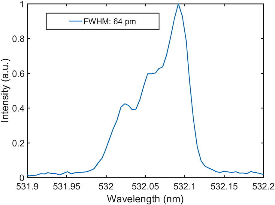
Figure 9. Spectrum of the SHG.
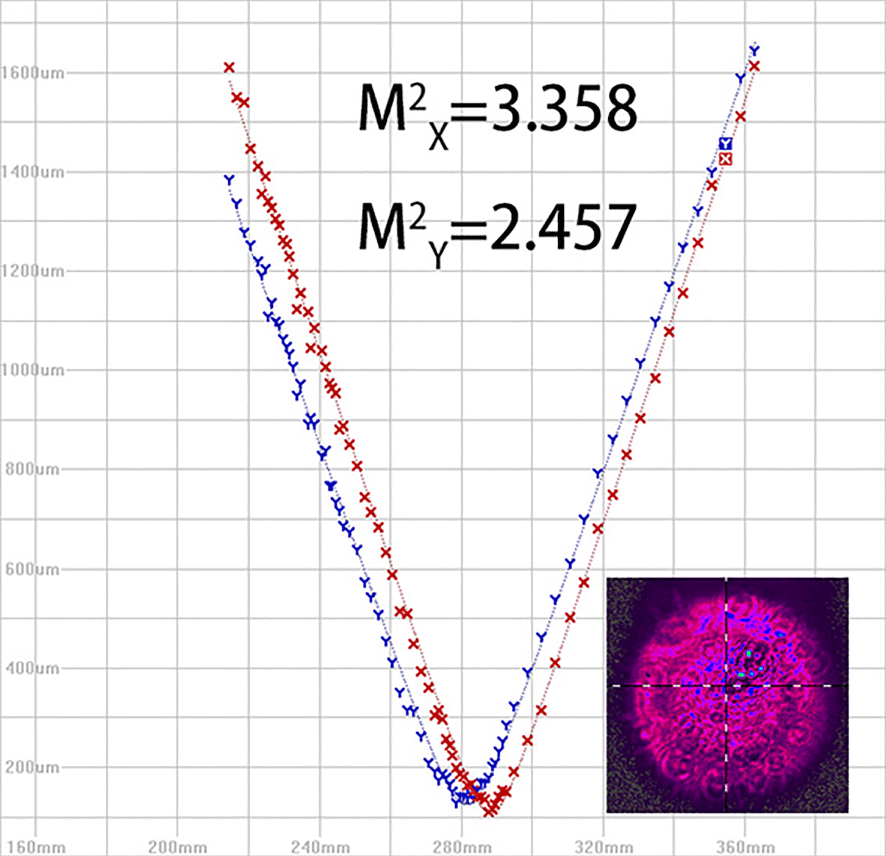
Figure 10. Beam quality of SHG.
4 Conclusion
In conclusion, we experimentally demonstrated a burst-mode picosecond laser system with a high pulse energy, high average power and high frequency doubling efficiency for space debris laser ranging. In this system, pulse stretching, beam splitting and reshaping by aspheric lenses are used to realize high-power laser output. After two-stage master traveling-wave amplification, the power of the fundamental beam is as high as 80 W with a power fluctuation of 0.56% over 30 min. By properly passing the beam through a type-I noncritical phase-matching LBO crystal, a 50 W second harmonic laser with less than 1% power fluctuation over 30 min is obtained at a pulse repetition rate of 1 kHz with a conversion efficiency of 68%. The laser system, which emits co-channel burst-mode pulses with a narrow linewidth and high intensity at 1064 and 532 nm, provides a promising light source for high-precision laser ranging of small space debris.
Acknowledgement
This research was supported by the National Natural Science Foundation of China (No. U1631240).


