


Introduction
Orbital angular momentum (OAM) beams have become an attractive alternative to traditional communication systems because of their ability to carry multiple data streams, thereby improving the spectrum efficiency and data rate in the wireless communication systems [Reference Tamburini, Mari, Sponselli, Thidé, Bianchini and Romanato1–Reference Yagi, Sasaki, Yamada and Lee3]. Therefore, methods to generate the OAM beams in the radio domain have been researched, and the various antenna structures or phase masks have been designed for the radiation of the same [Reference Chen, Zhou, Moretti, Wang and Li4]. However, these generated OAM beams are divergent in nature, which limits their usefulness in far-field communication at microwave and millimeter wave frequencies, where low half-power beamwidth radiation is required [Reference Wang, Park, Yang, Brüns, Kam and Schuster5]. This limitation can be overcome by using a metasurface lens (MSL) to converge the OAM beams generated by the various OAM-generating antennas [Reference Su, Zhang, Xiao, Song, Xiong, Xiao and Wang6], out of which the most frequently used OAM generation structure is the use of Uniform Circular Array (UCA) of the identical antenna elements [Reference Liu, Chen, Liu, Li, Chen and Mo7].
In the last three decades, several approaches have been made for the beam convergence of any antenna. Initially, a dielectric-based convex lens has been used that gives a significant amount of convergence and also improvement in gain in the main beam direction [Reference Piksa, Zvanovec and Cerny8]. Metasurfaces [MS] enable highly compact designs, which allow for miniaturization in microwave lens antennae. This is ideal for modern microwave devices where size and weight constraints are increasingly important. The MSLs are poised to significantly enhance the performance and functionality of microwave devices across various sectors, including point-to-point communications, radar, sensing, and imaging. The continuous advancements in metasurface design and fabrication are expected to broaden their application scope even further in the future. Due to the specific properties like polarization conversion, absorption [Reference Wang, Cai, Yang, Wu, Cheng, Chen, Luo and Li9–Reference Cai, Yang, Wu, Cheng and Li11], inverse Snell’s law, negative permeability, etc., the MS has attracted the attention of researchers [Reference Xiao, Su, Song, Li, Zhang, Lu and Wang12]. The convergence of the beam can also be achieved with the help of MSL. Various approaches have been made to converge the radiation pattern of an antenna by phase and amplitude control [Reference Sun, Xu, Yang, Chen, Wang, Yu, Yu and Wang13]. An array of rectangular patches of two layers has been used to converge the radiation pattern of the antenna [Reference Wang, Chen, Yu and Gao14]. MS has also been utilized to increase the operational bandwidth of a mode-reconfigurable OAM antenna by loading a metasurface layer on the driven patch [Reference Wu, Zhang, Ren, Huang and Wu15]. An approach for converging the OAM beam using a planar MSL has been made in which the conversion efficiency is very high, but the lens is bulky with three metallic layers [Reference Yi, Li, Feng, Ratni, Jiang, De Lustrac, Werner and Burokur16]. Other approaches for converging the OAM beam of ±1 and ±2 mode have been made, and a comparative analysis between the MSL and dielectric lens is also given [Reference Meng, Yi, Burokur, Kang, Zhang and Werner17]. These modes have also been simultaneously generated using coding metasurfaces [Reference Li, Li, Liu, He, Huang, Li and Cao18, Reference Li, Li, Huang, Liu, Li and Cao19]. The metasurface lens is very effective in beam convergence, but the transmission losses are high due to the six-layered metallic patch of the lens. The use of metasurface has a few drawbacks over many advantages. Although an MSL used here is for the convergence of OAM beams, it also reduces the overall radiation efficiency of the antenna in terms of conduction loss and surface waves (it can also get added to the radiation after diffraction from the edge of the substrate, but it is considered as a loss), and dielectric loss. Conversely, the MSL converges the diverging wave and improves the side lobe level and gain of the OAM antenna [Reference Pozar and Kaufman20].
This paper provides valuable insights into the design, fabrication, and measurement of an MSL for the convergence of OAM beams, contributing to the ongoing development of this emerging technology. The MSL is designed to converge both the first-order and second-order OAM beams generated by the eight-element UCA at the resonating frequency of 10 GHz, which makes these OAM beams to be used efficiently in far-field communication. The EM constitutive parameter of the MSL, including the relative refractive index, is analyzed to optimize the design. The designed UCA and MS-Lens are measured, which agrees well with the simulated results. Moreover, the mode purity analysis is performed, which confirms the negligible change in the phase distributions of the OAM beams for the corresponding modes after transmitting through the MSL.
Design and analysis of unit cell
The selection of unit cells plays a crucial role in designing an MS structure. Several structures are available that can be used for designing an MS lens. In [Reference Wang, Chen, Yu and Gao14], a metallic square patch on both sides of the substrate layer is used. In [Reference Chen, Ma, Zou, Jiang and Cui21], a single-layer square metallic ring is attached to the dielectric surface. We investigated some of the other combinations along with that available in the literature. We found that combining a metallic square patch and a square ring gives a better response in terms of transmission loss and also a wide range of refractive indices. Furthermore, we found that the figure of merit (FOM) of the proposed structure is better than the structures available in the literature.
The top and bottom view of the proposed metasurface unit cell is shown in Fig. 1. The top layer of the MSL is an array of square rings, and the bottom layer is an array of square patches; the optimized dimensions of which vary from lp = 1.5–2.5 mm, wp = 1.6–2.6 mm, and wr = 1 mm. While designing the unit cell, a scaling parameter S is taken to maintain the width of the square ring and the spacing between the adjacent unit cells.
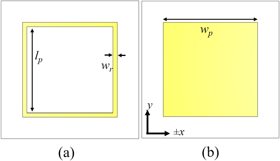
Figure 1. Unit cell of the proposed metasurface lens (a) top view and (b) bottom view.
Fig. 2 shows the transmission coefficient of the various combinations of the structure. Here, we found that the transmission loss is 0.008 dB for our proposed structure (square ring and patch) over the frequency from 8 to 12 GHz. Over the same frequency regime, a single-layer square ring has 0.008 dB transmission loss. For these unit cells, the transmission loss is constant over the frequency. The transmission loss varies over the frequency from 0.4 to 0.75 dB for the square metallic patch on both sides. On the other hand, loss is a crucial component of metasurfaces, which has a direct impact on their practical uses. We examine the FOM, which is defined as Re(n)/Im(n), where n is the relative refractive index of the MS unit cell, in order to assess the loss of the proposed metasurfaces. A FOM greater than 10 is often regarded as a low-loss metasurface [Reference Shin, Shen and Fan22]. Figure 3 shows the refractive index and FOM of the conventional metasurface unit cell (square patch and square ring) and the proposed unit cell structures.
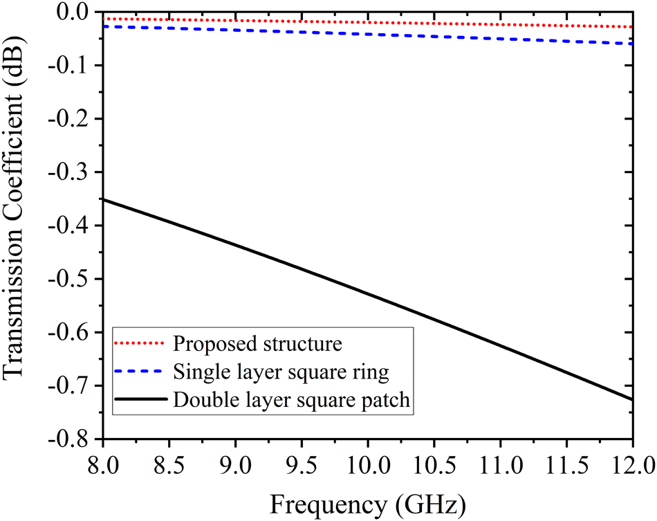
Figure 2. Transmission coefficients of various unit cell structures: (red dotted curve) – proposed unit cell, (blue dash curve) – single layer square ring, and (solid black curve) – double layer square patch.
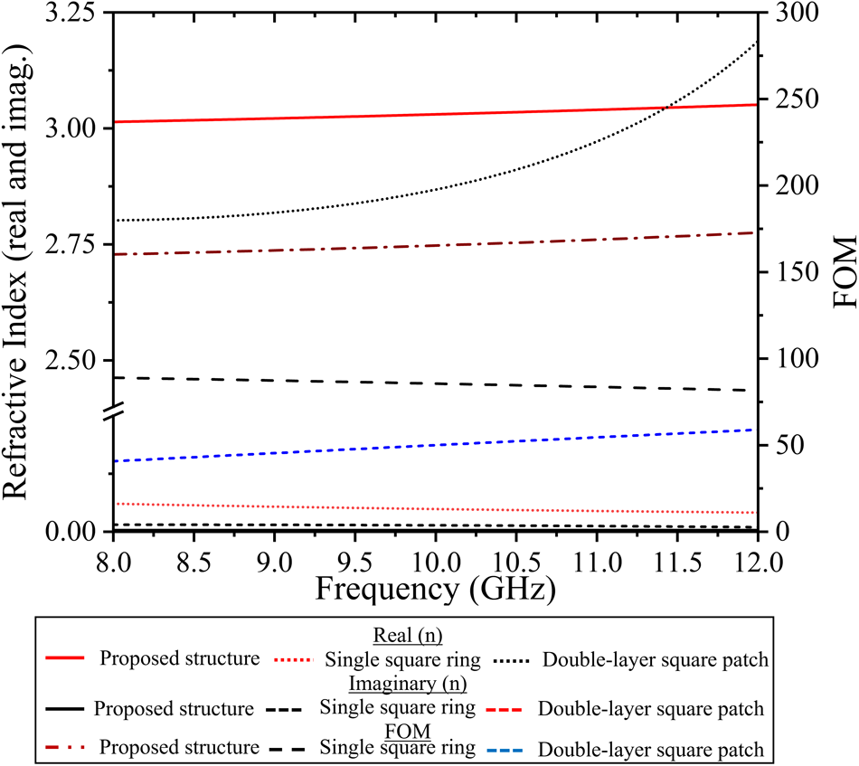
Figure 3. Refractive index (real and imaginary) of the single layer square ring, double layer square patch, and proposed unit cell in X-band and their figure of merit.
First, the proposed unit cell is analyzed to see the variation in the value of the refractive index of the unit cell as a transmissive element by varying the scaling parameter S. Fig. 4 shows that the value of the refractive index varies from 2.2 to 9 over the different value of the scaling parameters. The change over a large value of the refractive index of the unit cell is suitable for the lens. The simulation is performed using an FDTD-based CST Microwave Studio solver. The unit cell is first simulated with the flouquet ports at +z and -z (input and output) ports. The unit cell is considered periodic in the x-y plane with periodic boundary conditions. A linearly polarized wave source is considered at the port. The MS is made by printing the square patch on the top of the substrate and the square ring on the back side of the substrate. Afterward, the relative refractive index of the unit cell is analyzed by varying the size of the unit cell by scaling factor (S). In this article, the antenna radiates in the +z direction and is placed in the xy-plane.
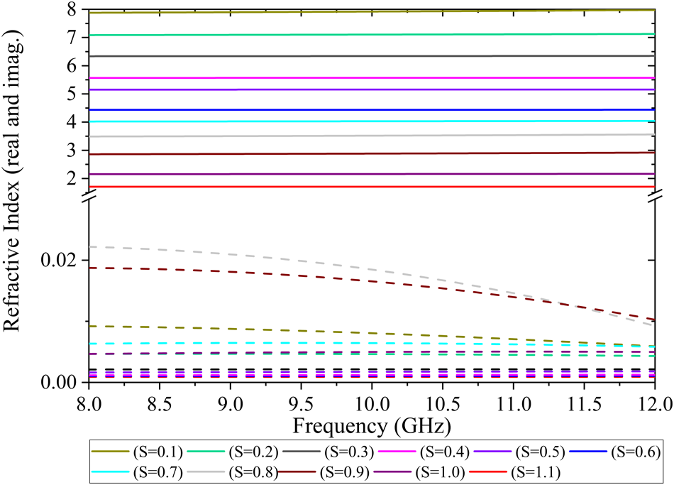
Figure 4. Variation in refractive index of the proposed unit cell with the scaling factor over the X-band frequency.
Placement of unit cell and metasurface lens design
As the value of the scaling parameter of the unit cell increases from 0.1 to 1.1, the value of the refractive index also changes from 8 to 1.85. This considerable variation in the value of the refractive index gives the freedom to design the MS lens using the proposed unit cell structure. We first determine the phase plot of the OAM antenna. Later, the near-field distance of the antenna is determined by trial–and–error approach in the simulator. Furthermore, the incident angle of the OAM beam has been analyzed in the x-y plane at certain distances in the radiating direction. The metasurface unit cell is placed accordingly at those places to get the same transmission angle in the radiating direction. The transmissive EM wave is generated from the array of unit cells of different sizes.
The placement of the unit cell is performed using the numerical study of the OAM beam phase front given in [Reference Meng, Yi, Burokur, Kang, Zhang and Werner17] to convert the low-gain incoming OAM beam to a high-gain transmitting OAM beam. The relative refractive index relation with the lens geometrical parameter is given by the formula
 \begin{equation}
n_{0}-n(r)= \frac{(\sqrt{F^{2}+r^{2}}-F)}{T}
\end{equation}
\begin{equation}
n_{0}-n(r)= \frac{(\sqrt{F^{2}+r^{2}}-F)}{T}
\end{equation}where F is the focal length,r is the radial distance of the lens from the center axis, and T is the thickness of the lens.
The MS is analyzed for +1, –1, +2, and –2 OAM modes. It has been found that the proposed MS lens can converge the incident OAM beams to the transmitted OAM beams with relatively narrower divergence angles for all the above modes. In order to generate OAM beams with first and second-order modes, the 8-element UCA of rectangular patches is designed at 10 GHz on a FR4 substrate ( $\varepsilon_{r}=$ 4.3, tan $\delta=$ 0.025, and h=1.6 mm ). The radius of the UCA is equal to λ, which is considered to maintain good isolation between the adjacent UCA elements. The corresponding OAM modes are generated by providing the required phase shifts between the adjacent elements [Reference Mohammadi, Daldorff, Bergman, Karlsson, Thide, Forozesh, Carozzi and Isham23]. For the experimental verification, the 8-element UCA for –1 mode generation is fabricated for which the feeding network has also been designed [Reference Bai, Tennant and Allen24], as shown in Fig. 5. The measured results of the reflection coefficient of the designed UCA with and without the MSL are shown in Fig. 6. The antenna is fed with a 50 ohm impedance coaxial line. From the figure, it can be seen that the input reflection coefficient of the antenna is minimum at 10 GHz and gives -30 dB without the MSL. After applying the MSL on top of the UCA, due to multiple reflections between the UCA and the bottom layer of the MS lens, the reflection coefficient is increased to -20 dB, which is also a very decent value for the antenna.
Figure 5. UCA for –1 mode generation of OAM beam. (a) Designed sample. (b) Fabricated prototype.
Figure 6. Measured input reflection coefficient of the UCA antenna, shown in Figure 5, without and with metasurface.
Results and discussion
The far-field radiation pattern of the antenna under test (AUT) with and without the MSL is measured. To measure the radiation pattern, the AUT is placed in the line of sight of a linearly polarized wideband reference horn antenna (1–18 GHz). Furthermore, the AUT is rotated from 0 to 360∘ . The AUT and reference horn antenna are placed at a calculated far-field distance of 1.90 meters, and the measurement is performed in an anechoic chamber. Under this condition, the main lobe direction is along  $\pm 29^{\circ}$ with a beam separation angle of 58∘. Then, we placed the MS lens at a distance of 50 mm (λ ×1.7) from the UCA along the radiating direction (z-axis). The beam incident at an angle of θi and the angle of refraction is θr. Here, we kept $\theta_{r}= 0^{\circ}$, which is constant at each value of θi. The value of θi depends on the radial distance of the incident beam from the center as shown in Fig. 7 As the radial distance increases, the angle of the incident beam also increases. Thus, the change in refractive index is required to get a plane wave in the z-direction. The concept has been explained in Fig. 7.
Figure 7. Placement of metasurface in the direction of OAM beam radiation showing convergence of the beam.
Furthermore, the electric field magnitude distribution of the radiation wave is analyzed to check the convergence of the wave after applying an MSL. Figure 8(a) and Fig. 8(b) shows the E-field distribution with and without the MSL, respectively. The figure clearly shows that the radiated beam is converged by the proposed MSL.
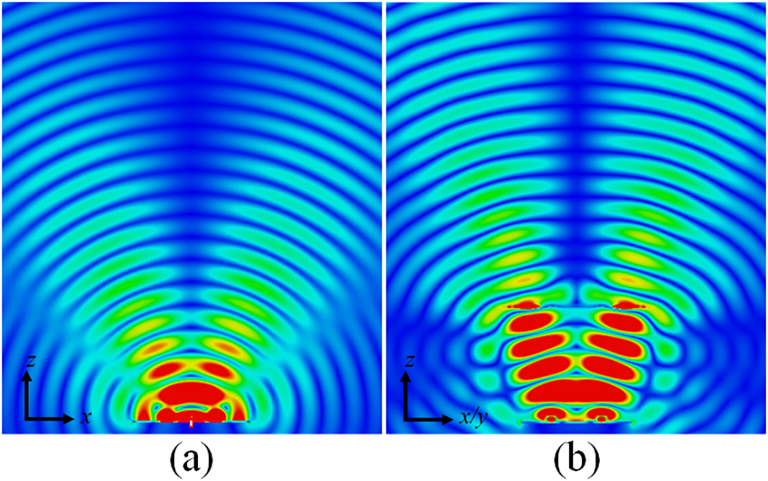
Figure 8. E-field pattern of the OAM antenna in ±1 mode (a) without MS lens and (b) with MS lens.
From Fig. 9(a), it can be seen that the radiation pattern of the UCA without the MS lens has a 58∘ separation angle between the main lobe direction in the H-plane, whereas the main lobe separation angle is reduced to 24∘ when the MS lens was kept between the UCA and the reference horn antenna. Moreover, it can be observed from the near-field phase distribution plot of the electric field, as shown in Fig. 12 that the use of the proposed MSL over the UCA does not disturb the phase distribution in the generated OAM modes and maintain the good mode purity after passing the beam through the MSL. Furthermore, the normalized radiation pattern of UCA without and with the MS lens has also been measured for the E-plane. It shows a similar radiation pattern due to symmetry of the UCA and MS lens along x- and y-directions. It is depicted in Fig. 9(b).
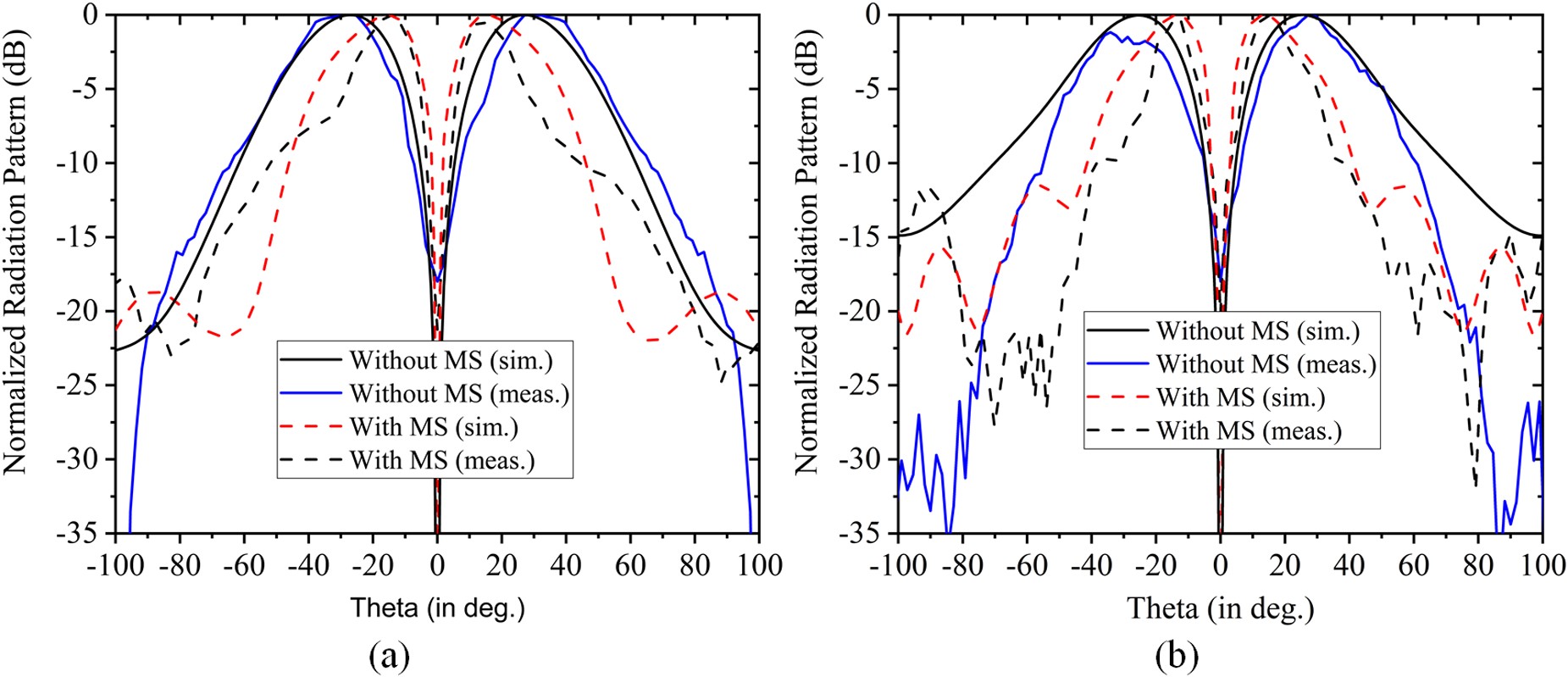
Figure 9. Normalized radiation pattern of the UCA with and without MS lens (a) H-plane and (b) E-plane.
A laboratory prototype of the MS lens is fabricated on a Rogers RT/Duroid 5880 substrate ( $\varepsilon_{r}=$ 2.2, tan $\delta=$ 0.001, and h=0.51 mm) and experimentally measured to cross verify the simulation results. The top and bottom view of the fabricated MS lens is shown in Fig. 10. The experimental setup of the proposed MSL for radiation pattern measurement is shown in Fig. 11. The experiment is performed in an anechoic chamber, where a wideband horn antenna of gain 10 dBi is used as a receiver and our test antenna as a transmitter.
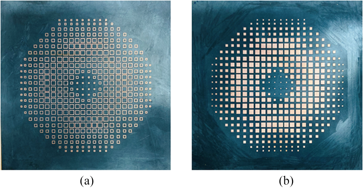
Figure 10. Fabricated MS lens on both sides of RT/duroid 5880. (a) Top view. (b) Bottom view.
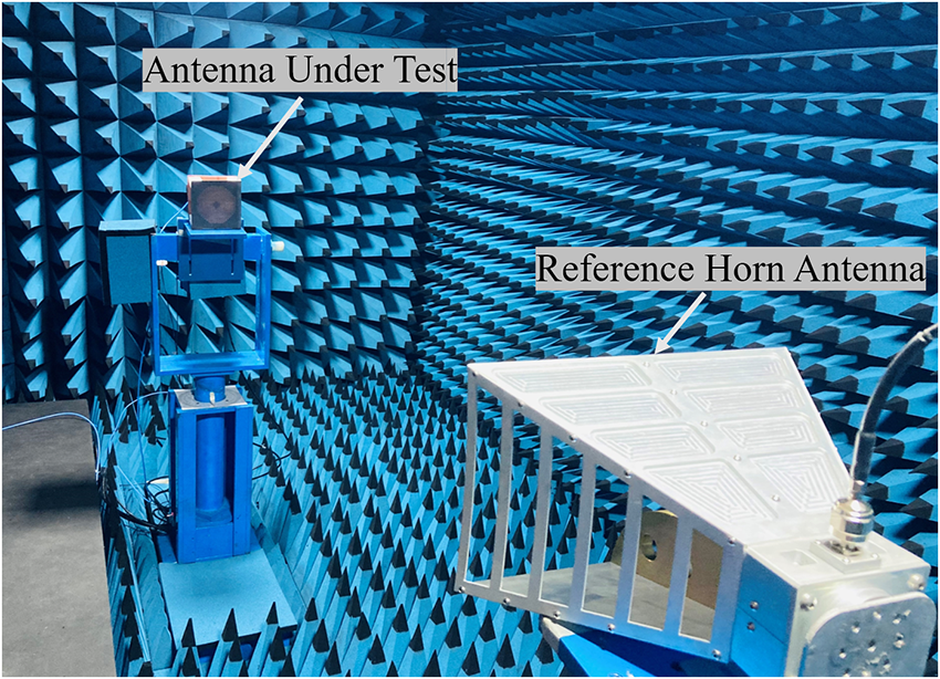
Figure 11. Measurement setup of the proposed structure.
The simulated near-field phase distributions of the electric field for both with and without MSL are shown in Fig. 12. The helical twists in the phase fronts of the radiated fields prove the generation of OAM beams with respective modes. It can also be observed from Fig. 12(b) and Fig. 12(d) that these phase fronts do not lose their originality after the beams pass through the proposed MSL. Therefore, the mode purity of the OAM beams is well maintained after the use of MSL. In order to prove this experimentally, the near-field measurements on the laboratory prototype of the UCA integrated with the proposed MSL is performed. The results obtained by this experimental study are shown in Fig. 13. These measured phase plots have a good similarity with that of simulated ones. However, the small deviation in the measured phase plots is due to the lesser distance of the scanning plane from the MSL than that taken in the simulation. This distance was taken during the measurements because of the limitations of the setup.
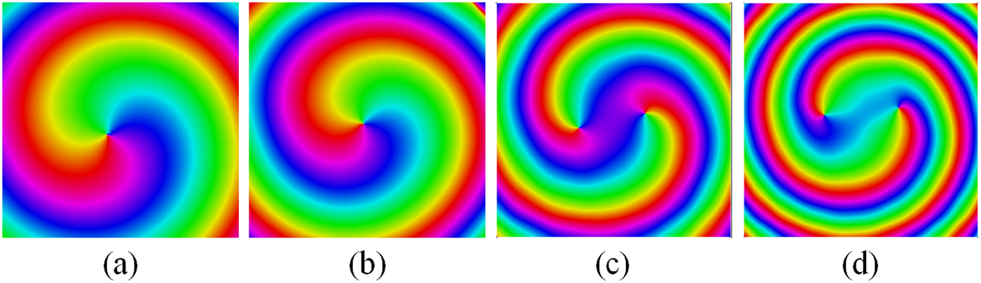
Figure 12. Simulated near-field phase plots at 10 GHz (a)  $l=-1$ mode without MSL, (b) $l=-1$ mode with MSL, (c) $l=-2$ mode without MSL, and (d) $l=-2$ mode with MSL
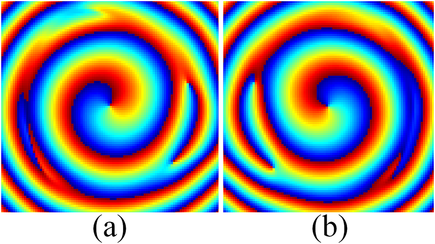
Figure 13. Measured near-field phase plots with MSL at 10 GHz (a)  $l=+1$ mode and (b) $l=-1$ mode
Mode purity analysis of the converged OAM beam
The mode purity analysis of the OAM beams further ensures the generation or propagation of the desired OAM modes as it evaluates the energy proportion in the designated mode over the entire OAM mode spectrum [Reference Guo, Zhao, Zhu, Xu and Zhang25]. It is well known that the circular array of identical antennas can generate the various OAM modes by giving the appropriate phase shift, which has also been verified experimentally by many researchers. However, in the case of an MSL for beam convergence, it is important to carry out the mode purity analysis to see the impact of the lens on the phase distribution of the input OAM beam. The electric field distribution in the observation plane before and after the application of the lens is sampled circularly with a radius of 4λ and 5λ for the first and second-order modes, respectively. Eventually, the mode purity is evaluated by performing the spectral analysis of the Fourier Transform of all the sample points using equations mentioned in [Reference Jack, Padgett and Franke-Arnold26].
Figure 14 shows the mode purity spectrum of the OAM beams generated at the resonating frequency of 10 GHz. Figure 14(a) shows the good mode purity of around 83 $\%$ for both the first and second-order OAM modes. After passing these OAM beams through the proposed MSL, the mode purity analysis is performed and shown in Fig. 14(b). It can be observed that the mode purity in first- and second-order OAM modes is around 80 $\%$, showing negligible variations in the phase distribution after passing through the MSL. Therefore, the proposed lens can converge the OAM beams by maintaining the helical phase distribution in the input OAM beams with good mode purity. The discrepancies in the simulated and measured results are primarily because of unavoidable fabrication errors and non-ideal measurement conditions. However, the experimental verification of the proposed MSL confirms the convergence of the OAM beam without disturbing its characteristics and is in good agreement with the simulation results.
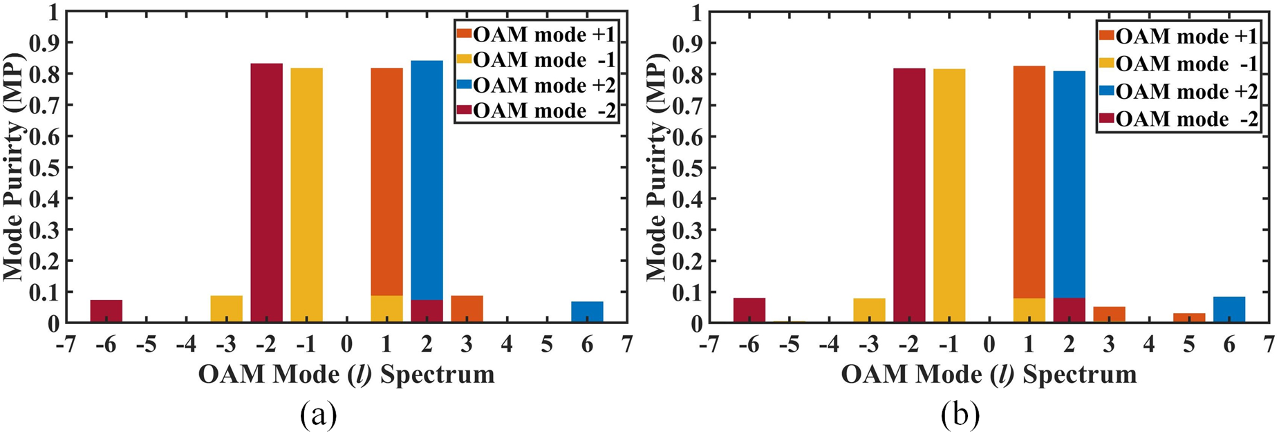
Figure 14. Mode purity spectrum of the OAM beams, (a) without lens, and (b) with lens.
Conclusion
A metasurface-based OAM beam convergence lens is designed and validated in this article. The unit cell consists of sqaure patch and square ring placed on the front and back side of the substrate. The MSL converges the incoming beam, both ±1 and ±2 modes, to a transmitting EM beam. The MS lens is integrated with the UCA at λ ×1.7 distance from the plane of UCA and can convert 58∘ divergent beam of ±1 mode to 24∘ of OAM beam without distortion in the phase. The same has been fabricated and measured for validation. To further validate the performance of the MSL, mode purity analysis was performed, which shows that the proposed MSL does not disturb the phase distribution in the OAM beam and maintains the purity of the OAM mode. The convergence of the OAM beams achieved by integrating the proposed MSL with UCA can make these beams cover a large distance and can be used especially in point-to-point and defense communications.
Data availability statement
The authors declare the transparency of the data used in this article.
Acknowledgements
The authors thank the Department of Electronics and Communication Engineering, Indian Institute of Technology Roorkee, for providing the facility and space to do the research work.
Competing interests
The author(s) declares none.

Vinit Singh Yadav was born in Jaunpur, Uttar Pradesh, India. He received his Master’s degree from IIT (BHU) Varanasi in 2018 and completed his Ph.D. degree in RF and Microwave Engineering at the Indian Institute of Technology (IIT) Roorkee in 2024. He is currently a Postdoctoral Researcher at the IHF, University of Stuttgart, Germany. His research focuses on metasurfaces, antenna, and microwave and millimeter wave measurement. He actively contributes to the academic community as a Reviewer to several reputed journals, including IEEE Transactions on Antennas and Propagation, IEEE Antennas and Wireless Propagation Letters (AWPL), Scientific Reports, IEEE Access, and IEEE Photonics Technology letters.

Yuvraj B. Dhanade received his M.Tech. degree in Communication Engineering from VIT University, Vellore, India, in 2017. He is a Research Scholar with the Department of Electronics and Communication Engineering, Indian Institute of Technology Roorkee, India. His research interests include antennas, metasurfaces, OAM beams, and MIMO.

Amalendu Patnaik (Senior Member, IEEE) received his Ph.D. degree in electronics from Berhampur University, Berhampur, India, in 2003. From 2004 to 2005, he was a Visiting Scientist with The University of New Mexico, Albuquerque, NM, USA. He is currently a Professor with the Department of Electronics and Communication Engineering, Indian Institute of Technology Roorkee, Roorkee, India. He has authored or co-authored more than 150 peer-reviewed papers in international journals and conferences. He also co-authored one book on Compact Antennas for High Data Rate Communication: Ultra-Wideband (UWB) and Multiple-Input Multiple-Output (MIMO) Technology (Springer) and one book chapter on Neural Networks for Antennas in Modern Antenna Handbook (Wiley). His current research interests include plasmonic antennas, antenna array signal processing, applications of soft-computing techniques in electromagnetics, CAD for patch antennas, EMI, and EMC. Dr. Patnaik was the recipient of the IETE Sir J. C. Bose Award in 2000, the URSI Young Scientist Award in 2005, and the BOYSCAST Fellowship from the Department of Science and Technology, Government of India, from 2004 to 2005. He was the Chairperson of the IEEE Roorkee Subsection from 2015 to 2017. He is currently the Chair of the IEEE Uttar Pradesh section AP-S Chapter. He was an IEEE AP-S Region-10 Distinguished Speaker from 2015 to 2016. He is an Editorial Board Member of the International Journal of RF and Microwave Computer-Aided Engineering (Wiley) and an Associate Editor for IEEE Antenna and Wireless Propagation Letters.


 Open access