Hostname: page-component-78c5997874-xbtfd Total loading time: 0 Render date: 2024-11-13T04:49:23.921Z Has data issue: false hasContentIssue false

Flow–acoustic resonance mechanism in tandem deep cavities coupled with acoustic eigenmodes in turbulent shear layers

Published online by Cambridge University Press:  05 April 2024

Peng Wang
Affiliation:
Turbomachinery Institute, School of Mechanical Engineering, Shanghai Jiao Tong University, Shanghai 200240, PR China Gas Turbine Research Institute, Shanghai Jiao Tong University, 800 Dongchuan Rd, Shanghai 200240, PR China
Sichang Jia
Affiliation:
Turbomachinery Institute, School of Mechanical Engineering, Shanghai Jiao Tong University, Shanghai 200240, PR China Gas Turbine Research Institute, Shanghai Jiao Tong University, 800 Dongchuan Rd, Shanghai 200240, PR China
Zheng He
Affiliation:
Turbomachinery Institute, School of Mechanical Engineering, Shanghai Jiao Tong University, Shanghai 200240, PR China Gas Turbine Research Institute, Shanghai Jiao Tong University, 800 Dongchuan Rd, Shanghai 200240, PR China
Chuangxin He
Affiliation:
Turbomachinery Institute, School of Mechanical Engineering, Shanghai Jiao Tong University, Shanghai 200240, PR China Gas Turbine Research Institute, Shanghai Jiao Tong University, 800 Dongchuan Rd, Shanghai 200240, PR China
Hyung Jin Sung
Affiliation:
Department of Mechanical Engineering, Korea Advanced Institute of Science and Technology, 291 Daehak-ro, Yuseong-gu, Daejeon 34141, Korea
Yingzheng Liu*
Affiliation:
Turbomachinery Institute, School of Mechanical Engineering, Shanghai Jiao Tong University, Shanghai 200240, PR China Gas Turbine Research Institute, Shanghai Jiao Tong University, 800 Dongchuan Rd, Shanghai 200240, PR China
*
Email address for correspondence: yzliu@sjtu.edu.cn

Abstract

This study presents the interplay of flow and acoustics within tandem deep cavities, focusing on the resonance mechanism occurring between turbulent shear layers and acoustic eigenmodes. The arrangement inside the tandem deep cavities includes both close and remote configurations. A combined fully coupled and decoupled aeroacoustic simulation strategy was devised. Employing an advanced high-order spectral/hp element method in conjunction with implicit large eddy simulation, the nonlinear compressible Navier–Stokes equations were solved to acquire internal flow–acoustic resonant field. In parallel, the linearized Navier–Stokes equations were tackled to determine coherent shear layer perturbations with external acoustic forcing. Based on acoustic measurements, the mainstream Reynolds number approaches approximately $R{e_{in}} = {O}({10^5})$, where we identified the presence of frequency lock-in and a resonance range. Aeroacoustic noise sources were examined by implementing spectral proper orthogonal decomposition to decompose the pressure fields into hydrodynamic and acoustic components. As feedback intensified, the flow characteristics by the acoustic forcing effect and the flow-interactive effect were categorized according to the development of concurrent turbulent shear layers. Subsequently, the alternating and synchronous behaviours of concurrent shear layers resonated with the out-of-phase and in-phase acoustic eigenmodes were identified, and the corresponding large-scale counter-rotating vortex pairs and co-rotating vortex structures at the cavity entrances were extracted. The acoustic power generated by the Coriolis force was calculated using Howe's vortex-sound analogy, and the aeroacoustic energy transfer mechanism between large-scale shear layer vortices with acoustic eigenmodes was further explored. Finally, a linear response of coherent perturbations of the concurrent shear layers by external acoustic forcing was established. The amplification of flow in the streamwise direction toward the main duct led to the formation of coherent vortex structures, accompanied by separation bubbles into the main duct.

Type
JFM Papers
Copyright
© The Author(s), 2024. Published by Cambridge University Press

1. Introduction

Flow–acoustic interaction is a common issue in modern engineering applications. This intricate coupling frequently gives rise to undesirable consequences such as elevated noise emissions, structural vibrations and even acoustic fatigue. These adverse effects, in turn, exert an impact on multiple fronts, including compromised aerodynamic performance, curtailed operational cycles and diminished service lifespans of associated equipment and facilities. Addressing and mitigating flow–acoustic interaction is imperative to ensuring the longevity, efficiency and effectiveness of engineering systems. By effectively managing this interaction, engineers and researchers can foster enhanced operational stability, reduced noise pollution and prolonged service intervals, contributing to the overall reliability and sustainability of critical machinery and infrastructure.

Depending on the acoustic oscillation intensity, flow–acoustic interaction can be classified into two types. The first type is characterized by weak flow–acoustic coupling, observed in open spaces, such as instances of jet noise and airfoil noise. The interplay between acoustic phenomena and fluid dynamics is relatively subtle, resulting in less pronounced effects on the overall system behaviour. The second type involves strong flow–acoustic coupling, encountered in enclosed spaces. This encompasses phenomena such as confined cavity noise and duct acoustics. In such settings, the interaction between the acoustics and fluid dynamics exerts a more profound influence, leading to more conspicuous repercussions on the system's behaviour. In weak couplings, the aerodynamic noises would be generated by turbulent flow behaviours under the effects of Kelvin–Helmholtz instability, boundary layer transition or flow separations, while the flow dynamics is almost unaffected by the radiated acoustic waves (Ahuja & Mendoza Reference Ahuja and Mendoza1995). In strong couplings, however, aero-acoustical energy can be accumulated and high-intensity acoustic counterforces are established, especially when the natural acoustic eigenmodes of the enclosed volume are excited by the intrinsic turbulent fluctuations, originating from flow passing the structural discontinuities. In this regard, the magnitude of the acoustic particle velocity reaches the same order as the mainstream flow velocity, the acoustic forcing on the flow dynamics is not negligible but inversely amplifies the turbulent fluctuations into the resonant mode (Hirschberg & Rienstra Reference Hirschberg and Rienstra2004). Such a phenomenon has been reported in the F35B fighter, the annular combustion chamber and piping system in nuclear power plants and in gas transport stations. Comprehensive understanding of the flow–acoustic interaction mechanism containing the elevated unsteady flow behaviours and associated aeroacoustic energy production is highly desirable for the related scientific community and engineering components.

The present study focuses on the interaction between turbulent shear layers of cavity flow with internal and external acoustic forcing, respectively. In general, depending on the length-to-depth ratio $({L_c}/{D_c})$ of a cavity, it can be classified into shallow cavity with ${L_c}/{D_c} > 1$ and deep cavity with ${L_c}/{D_c} < 1$. In comparison, aerodynamic noises radiated from shallow cavities subjected to high Mach number incoming flow can be formulated by the Rossiter formulation, and the feedback mechanism be described as shear layer perturbations being gradually amplified along the cavity mouth, then impinging on the downstream cavity corner and producing acoustic waves, which propagate upstream and excite further shear layer instabilities to close the loop (Rowley, Colonius & Basu Reference Rowley, Colonius and Basu2002). Differently, strong flow–acoustic couplings occur within deep cavities even at quite low Mach numbers, inducing strong aeroacoustic pulsations, with amplitudes close to or exceeding the dynamic pressure head of the mainstream flow. Such strong aeroacoustic pulsations can be attributed to two effects, i.e. the amplification of incident acoustic waves into elevated external acoustic forcing and the excitation of natural acoustic eigenmodes into self-sustained internal acoustic forcing.

By conducting a global stability analysis with exterior disturbance, the Kelvin–Helmholtz instability of a cavity shear layer can be strengthened by enhanced aeroacoustic feedback at selected frequencies (Yamouni, Sipp & Jacquin Reference Yamouni, Sipp and Jacquin2013). According to Nakiboğlu, Manders & Hirschberg (Reference Nakiboğlu, Manders and Hirschberg2012), this feedback effect was produced by the resultant intensive velocity fluctuations and continuous vorticity convection from shedding vortices at the leading edge of the cavity. Bourquard, Faure-Beaulieu & Noiray (Reference Bourquard, Faure-Beaulieu and Noiray2021) experimentally measured and theoretically modelled the aeroacoustic feedback using stochastic differential equations and Fokker–Planck equations; the intermittency from stable to unstable feedback was observed in the vicinity of supercritical Hopf bifurcations. In another aspect, Shaaban & Ziada (Reference Shaaban and Ziada2018a) constructed acoustic standing-wave oscillations along with mainstream flow passing through multiple cavities; elevated acoustic pulsations were identified from different coupling combinations among hydrodynamics modes and harmonic acoustic modes. By performing acoustic forcing at the end of a deep cavity through the linearized Navier–Stokes equation (LNSE) and compressible large eddy simulation (LES), Boujo, Bauerheim & Noiray (Reference Boujo, Bauerheim and Noiray2018) identified the amplification of kinetic energy and nonlinear saturation mechanism of turbulent shear layers when increasing the forcing intensity.

Internal acoustic forcing is closely related to natural acoustic modes, such as longitudinal modes of multiple shallow cavities, diametral modes of annular cavities and depth-oriented standing-wave modes of deep cavities. The excitation of these acoustic modes gives rise to remarkable acoustic pressure pulsations, trapped within the enclosed cavity volume or radiated away depending on the direction of acoustic mode. Under the influence of aeroacoustic feedback from longitudinal acoustic modes, the shear layer oscillations inside multiple cavities/side branches or a corrugated pipe present a similar feature with well-organized vortex shedding behaviour (Nakiboğlu et al. Reference Nakiboğlu, Belfroid, Golliard and Hirschberg2011; Shaaban & Ziada Reference Shaaban and Ziada2018b). Due to the special azimuthal characteristics of the diametral acoustic mode, the interactive shear layers demonstrate an intensified three-dimensionality and even a spinning rotation behaviour (Faure-Beaulieu, Pedergnana & Noiray Reference Faure-Beaulieu, Pedergnana and Noiray2023a; Faure-Beaulieu et al. Reference Faure-Beaulieu, Xiong, Pedergnana and Noiray2023b). These observations were corroborated through phase-locked particle image velocimetry (PIV) measurements (Ziada, Bolduc & Lafon Reference Ziada, Bolduc and Lafon2017) and high-fidelity LES simulations (Abdelmwgoud, Shaaban & Mohany Reference Abdelmwgoud, Shaaban and Mohany2020; Wang et al. Reference Wang, Deng, Mao, He and Liu2020). As for the depth-oriented acoustic mode, the direction of its acoustic particle velocity is generally perpendicular to that the streamwise-transported shear layer. This configuration results in a more significant production of acoustic power under the influence of the Coriolis force. According to Bruggeman et al. (Reference Bruggeman, Hirschberg, van Dongen, Wijnands and Gorter1991), Tonon et al. (Reference Tonon, Hirschberg, Golliard and Ziada2011a), three kinds of shear layer behaviours can be classified with respect to the dimensionless acoustic pulsation amplitude (${u_a}/{U_{in}}$, ${u_a}$ is the amplitude of acoustic particle velocity and ${U_{in}}$ is the mainstream velocity at the inlet): linear amplification of shear layer with a low-amplitude regime of ${u_a}/{U_{in}} < {O}({10^{ - 2}})$, nonlinear growth of the shear layer due to the concentration of emergent shedding vorticity with a moderate-amplitude regime of ${O}({10^{ - 2}}) < {u_a}/{U_{in}} < {O}({10^{ - 1}})$ and geometrical sensitivity of the shear layer with a high-amplitude regime of ${u_a}/{U_{in}} = {O}(1)$. Especially, the high-amplitude acoustic pulsations by the depth-oriented acoustic mode and its geometric sensitivity were confirmed by Larchevêque et al. (Reference Larchevêque, Sagaut, Lê and Comte2004); Thornber & Drikakis (Reference Thornber and Drikakis2008). With periodic deep cavities in close arrangement along a lined wall surface, convective aeroacoustic instability by coupling between the grazing shear flow and incident acoustic waves was also confirmed by Dai & Aurégan (Reference Dai and Aurégan2018). Further exploration of the effects of the geometrical arrangement and acoustic forcing on the dynamics of turbulent shear layers should provide valuable insights for the field of cavity noise, enabling the development of more efficient and adaptable systems.

The objective of the present study is to explore the interaction between a streamwise shear layer and perpendicular acoustic forcing with high amplitude using a hybrid computational aeroacoustics method and acoustic measurements. To strengthen the novelty and complexity, we focus on the resonant behaviours and coherent perturbations of the turbulent concurrent shear layers by the high-intensity acoustic forcing inside the ducted tandem deep cavities. A combined numerical strategy containing fully coupled and decoupled aeroacoustic simulation was performed to investigate the following issues: first, we acquired the fully coupled aeroacoustic fields with self-sustained acoustic oscillations by using a high-order spectral/hp element method and directly solving the nonlinear compressible Navier–Stokes equations. Next, we determined the coherent perturbations of a shear layer perturbated purely by external acoustic forcing through solving the compressible LNSEs. Based on the simulation results, the aeroacoustic noises generated by concurrent turbulent shear layers were firstly investigated in conjunction with spectral proper orthogonal decomposition (SPOD). The intensified flow characteristics by the acoustic eigenmodes were categorized according to the shear layer development tendency. The kinematics of shear layer vortices and coherent shear layer perturbations in response to internal and external acoustic forcing with out-of-phase or in-phase oscillations were examined. The aeroacoustic energy transfer mechanism between the flow field and acoustic field was further explored.

2. Problem formulation and acoustic measurement

2.1. Problem description

A depiction of the flow–acoustic interaction within tandem deep cavities is illustrated in figure 1(a): concurrent shear layers are formed when flow passes the entrances of two cavities; the internal acoustic forcing can originate from the excited acoustic eigenmodes. Similar to a single cavity, the shear layer perturbations can excite the quasi-trapped acoustic modes of each cavity and the acoustic oscillation amplifies the shear layers in a feedback way. Differently, more complex interactions appear as the two isolated cavities are connected by the global acoustic eigenmode. This complexity has been confirmed by acoustic measurements of Ziada & Bühlmann (Reference Ziada and Bühlmann1992), Okuyama et al. (Reference Okuyama, Tamura, Takahashi, Ohtsuka and Tsubaki2012) and Tonon, Willems & Hirschberg (Reference Tonon, Willems and Hirschberg2011b). The excited acoustic pulsations would not only be trapped inside the cavities, but also propagate outside along the main duct. More attention should be paid on the far upstream and downstream equipment. These clarifications can be confirmed by exploring the acoustic eigenmodes using acoustic modal analysis to solve the acoustic Helmholtz equation (Barbieri & Barbieri Reference Barbieri and Barbieri2006). In the acoustic modal analysis, tetrahedral elements were generated to discretize the acoustic domain, ensuring at least five grid nodes per acoustic wavelength. The inlet and outlet were treated as non-reflective acoustic soft boundaries, allowing acoustic waves to pass. Results are illustrated in figure 1(b), in which four configurations with ${\rm \pi} = L/{D_m} = 1,\; 4,\; 8,\; 16$ are selected for demonstration. Here, L is the distance between the vertical centrelines of the tandem deep cavities and ${D_m} = 40\ \textrm{mm}$ is the size of the square cross-section of the main duct. The length, depth and width of the two cavities are equally fixed at ${L_c} = 0.8{D_m}$, ${D_c} = 4{D_m}$ and ${W_c} = {D_m}$. Here, a depth-to-length ratio of 5 : 1 is utilized to effectively facilitate the excitation of the depth-oriented acoustic mode. A spanwise ratio of 1 : 1 between the main duct and tandem deep cavities promotes a quasi-two-dimensional flow feature around the centreplane of the main duct. With ${\rm \pi} = 1,4$ of close arrangement, their first-order eigenmodes demonstrate an antisymmetric standing-wave feature, as an out-of-phase acoustic pressure distribution is identified inside the tandem deep cavities. With ${\rm \pi} = 8,\; 16$, their first-order eigenmodes demonstrate a symmetric standing-wave feature, as an in-phase acoustic pressure distribution is identified inside the tandem cavities even in faraway arrangements, while an out-of-phase acoustic pressure is identified at the middle section of the main duct. In comparison, the second-order eigenmodes are harmonics of the first-order eigenmodes, but the acoustic pressure distribution is not a purely standing-wave feature due to propagation along the main duct.

Figure 1. (a) Schematic of flow–acoustic interaction within tandem deep cavities; (b) contour plots of the acoustic eigenmodes corresponding to the four configurations with ${\rm \pi} = 1,\; 4,\; 8,\; 16$; the first row represents the first-order mode and the second row represents the second-order mode.

2.2. Acoustic measurements

A schematic diagram of the experimental set-up for acoustic measurements of the ducted tandem deep cavities is illustrated in figure 2(a). This set-up includes the construction of an open-circuit wind channel. To attain a low background noise level and maintain a stable air temperature within the wind channel, the air-breathing running mode of the downstream fan was activated. As part of the set-up, a sizable silencer was constructed and integrated. To attain a consistent inflow characterized by low turbulence intensity, we employed a diffuser with a 6 : 1 contraction ratio, along with the incorporation of a honeycomb layer and two wire-mesh layers at the inlet section. Two acoustic liners, optimized for frequencies exceeding 200 Hz, were crafted and positioned both upstream and downstream of the test section to mitigate the reflection of acoustic waves within the wind channel. The total length of the experimental set-up extended to a measurement of 8 metres. Here, we focus on two variables, i.e. the mainstream Reynolds number $(R{e_{in}})$ and the distance ratio between the two deep cavities. The range of $R{e_{in}}$ varies from $0.2 \times {10^5}$ to $2 \times {10^5}$ considering the side length $({D_m})$ of the mainstream duct and the mainstream velocity (${U_{in}}$: 7.5–75 m s−1). The maximum mainstream Mach number $(M{a_{in}})$ remains below 0.3, indicative of an incompressible air environment within the wind channel. A fully developed turbulent flow profile can be achieved as the leading edge of the upstream deep cavity located almost $50{D_m}$ downstream of the inlet diffuser. As a result, the inlet turbulence intensity was measured to be below 2 % using a hot-wire measurement; the maximum total sound pressure level was below 70 dB with high-speed running of the fan, far less than the acoustic oscillation intensity. A dynamic pressure transducer array with a total of 11 PCB-103B02 sensors was flush mounted at the backplate of the ducted tandem deep cavities to detect the frequency, amplitude and waveform of the excited acoustic modes. The pressure signals were simultaneously measured by an NI-cDAQ-9172 data acquisition equipment at a sampling frequency of 51.2 kHz. For demonstration purposes, the monitoring location was chosen to be at the endplate of the upstream cavity, which corresponds to the antinode of the acoustic eigenmode. Since this position is distant from the mainstream flow and acts as a flow dead zone, the measured pressure fluctuations can be considered as purely acoustic pulsations.

Figure 2. (a) Experimental set-up of acoustic measurements for tandem deep cavities; (b) plots of r.m.s. of wall pressure fluctuation as a function of mainstream Reynolds number, the selected monitor is locating at the endplate of upstream deep cavity; (c) plots of SPSLs; (d) spectrogram for the four configurations with ${\rm \pi} = 1,\; 4,\; 8,\; 16$.

In figure 2(b), we plotted the root mean square (r.m.s.) of the measured acoustic pulsations, normalized by the inlet dynamic pressure head, as a function of the mainstream Reynolds number. Within specific ranges of $R{e_{in}}$, the flow passing through the tandem cavities can induce acoustic resonances owing to the aeroacoustic feedback occurring between concurrent shear layers and their associated natural acoustic eigenmodes. Comparatively, the configuration with ${\rm \pi} = 8$ gives rise to the strongest acoustic pulsations, then the configuration with ${\rm \pi} = 1$. As for ${\rm \pi} = 8$, an obvious range of $0.8 \times {10^5} \le R{e_{in}} \le 1.7 \times {10^5}$ can be identified with essentially intensified acoustic pulsations; the maximum amplitude reaches two times of the inlet dynamic pressure head at $R{e_{in}} = 1.17 \times {10^5}$. It is noteworthy that the resultant acoustic particle velocity ratio reaches ${u_a}/{U_{in}} = 0.76$, which corresponds to the high-amplitude regime according to Bruggeman et al. (Reference Bruggeman, Hirschberg, van Dongen, Wijnands and Gorter1991) and Tonon et al. (Reference Tonon, Hirschberg, Golliard and Ziada2011a). As for ${\rm \pi} = 1$, the Reynolds number range with intensified acoustic pulsation amplitudes remains similar to the configuration with ${\rm \pi} = 8$, the maximum amplitude reaches 1.5 times of the inlet dynamic pressure head at $R{e_{in}} = 1.03 \times {10^5}$ and the resultant acoustic particle velocity ratio reaches ${u_a}/{U_{in}} = 0.57$ within the high-amplitude regime. In this configuration, another peak value of 0.8 times the inlet dynamic pressure head, which has an acoustic particle velocity ratio of 0.38, can also be found at ${R{e_{in}} = 1.29 \times {10^5}}$. As for ${\rm \pi} = 4,\; 16$, the excited acoustic pressure pulsations were relatively attenuated, the maximum values are below 0.4 times the inlet dynamic pressure head and the acoustic particle velocity ratios drop to ${u_a}/{U_{in}} < {O}({10^{ - 1}})$, corresponding to a moderate-amplitude regime. The amplitude discrepancy can be explained in view of the acoustic damping coefficient $(\xi )$ of the excited acoustic eigenmodes. As the acoustic eigenmodes were determined by solving the eigenvalue problem of the acoustic Helmholtz equation, one can obtain the real part and imaginary parts of their eigenvalues $({\lambda _a} = a + bi)$. The real part (a) represents the eigenfrequency of an acoustic eigenmode, while the imaginary part can be used to calculate the acoustic damping coefficient $(\xi = b/\sqrt {{a^2} + {b^2}} )$. Here, a larger damping coefficient represents more potential dissipation within an acoustic system. In our study, the derived damping coefficients for a tandem deep cavity with close and half-wavelength arrangements are ${\xi _{{\rm \pi} = 1}} = 0.015$, ${\xi _{{\rm \pi} = 8}} = 0.0012$, respectively. Consequently, the half-wavelength arrangement is found to induce the most robust acoustic pulsations.

In terms of the frequency information, the sound pressure spectrum levels (SPSLs) were calculated through the fast Fourier transformation method to delineate the acoustic spectra at the pressure sensors. The spectrograms in figure 2(d) illustrate that the fundamental frequencies of the above-mentioned aeroacoustic instabilities are 480 Hz for ${\rm \pi} = 1$ and 520 Hz for ${\rm \pi} = 8$, which are close to the first-order acoustic eigenmodes in figure 1(b). Beyond this fundamental frequency, several high-order harmonic frequencies are also highlighted in the spectrograms. In accordance with Ziada & Lafon (Reference Ziada and Lafon2014), such a frequency lock-in phenomenon confirms the occurrence of flow–acoustic resonance by the natural acoustic eigenmodes. Four quantitative plots with respect to the intensified acoustic pulsations are plotted in figure 2(c). The discrepancies between the experimental measurements and acoustic modal analysis are around 2 %, which could be attributed to the turbulence interaction effect. Accounting for the flow convection effect tends to marginally elevate the predicted eigenfrequencies. In addition, the slight frequency changes of the measured pressure pulsations at different Reynolds numbers may be attributed to the transport speed of the shear layer vortex, according to Tonon et al. (Reference Tonon, Hirschberg, Golliard and Ziada2011a).

In addition to frequency lock-in phenomenon at a single pressure monitor, we also identified the acoustic waveform from the dynamic pressure sensor array and explored their spatio-temporal evolution, which are illustrated in figure 3. The results further confirm the correspondence of the excited acoustic pulsations with the natural acoustic eigenmodes of the duct–cavity configurations. Here, the three flow conditions with ${\rm \pi} = 1$, $R{e_{in}} = 1.03 \times {10^5}$, ${\rm \pi} = 1$, $R{e_{in}} = 1.29 \times {10^5}$ and ${\rm \pi} = 8$, $R{e_{in}} = 1.18 \times {10^5}$ were analysed. Sinusoidal features of the identified acoustic waveform for the two configurations are highly consistent with the acoustic pressure distribution of their first-order acoustic eigenmodes. A plausible interpretation of the discrepancies in amplitudes will be discussed using the following numerical simulation results. A comparative view between the two configurations demonstrates that anti-phase propagation motions of the excited acoustic waves can be found in the tandem deep cavities in close proximity; while closely in-phase propagation motions are found for the tandem deep cavities in the latter configuration. Especially, the acoustic pressure pulsations in the lengthy main duct demonstrate anti-phase propagation motions with the above-mentioned synchronous tendencies between the faraway-arranged tandem deep cavities. Such an interesting special phenomenon was attributed the equivalence between the distance and sum of the tandem deep cavities, serving as a half-wavelength arrangement as their distance is equal to the half of the acoustic wavelength ($\lambda = {c_a}/{f_a} \approx 640\ \textrm{mm}$, with ${c_a}$ the sound speed and ${f_a}$ the eigenfrequency of the first-order acoustic eigenmode). These observations, in terms of the intensified pulsations, locked frequencies and in-phase or out-of-phase waveform of the measured acoustic pressure pulsations, strongly validate the occurrence of resonance between the ongoing concurrent shear layers and the natural acoustic eigenmodes.

Figure 3. Waveform identification (a), spatio-temporal evolution of the flow-excited acoustic pulsations along the ducted tandem deep cavities with ${\rm \pi} = 1$, $R{e_{in}} = 1.03 \times {10^5}$ (b) and $R{e_{in}} = 1.29 \times {10^5}$ (b); and ${\rm \pi} = 8$, $R{e_{in}} = 1.18 \times {10^5}$ (d,e). The white square symbols in (a) and (d) denote the sensor locations; in (b,c) and (e), the abscissa denotes the sensor number, starting at the endplate of the upstream cavity, the time intervals were sampled equally within one acoustic period corresponding to the fundamental frequency.

3. Fully coupled aeroacoustic simulation

3.1. High-order spectral/hp element method

The flow–acoustic interaction problem can be described by the nonlinear Navier–Stokes equations, containing the continuity, momentum and energy equations. In the present study, both the incompressible and compressible governing equations are solved for comparison, which artificially highlights the acoustic forcing effect on the turbulent shear layers. A spectral/hp element discretization method, which is implemented in the opensource package of Nektar++ (Cantwell et al. Reference Cantwell2015; Moxey et al. Reference Moxey2020), is used to solve the governing equations. This discretization approach combines the inherent geometric flexibility of the finite-element method with the exponential convergence and superior accuracy of the spectral method. This is realized by employing high-order Lagrangian interpolations in the finite-element formulation's expansion base function. Consequently, resolution convergence can be achieved by refining the mesh distribution (h-type refinement), or by increasing the interpolation order, Np, within the basis expansion (p-type refinement). Spectral/hp element discretization serves as the underpinning approximation for both continuous Galerkin (CG) and discontinuous Galerkin (DG) formulations. Fundamental information of the spectral/hp method can be found in Karniadakis & Sherwin (Reference Karniadakis and Sherwin2005), and an outline is provided herein. In general, the solution domain $\textrm{(}\varOmega \textrm{)}$ is segregated into ${N_e}$ non-overlapping elements $({\varOmega _e})$. Within each of these elements, we then seek approximate solutions, ${\boldsymbol{u}^\delta }$, belonging to the finite-element space

(3.1)\begin{equation}{\chi ^P} = \{ \phi \in {L^2}(\varOmega )|\phi {|_{{\varOmega _e}}} \in {\mathrm{{\mathcal{P}}}_P}({\varOmega _e})\} ,\end{equation}

where ${\mathrm{{\mathcal{P}}}_P}({\varOmega _e})$ is the space of polynomials of order Np defined in the element ${\varOmega _e}$.

In this work, the incompressible Navier–Stokes equations are solved via a velocity correction scheme where velocity and pressure are typically decoupled. A weak pressure Poisson problem is formulated by taking the inner product over the domain ${\varOmega _e}$ with respect to the gradient of test function, $\boldsymbol{\nabla }v$, i.e.

(3.2)\begin{align}\int_{{\varOmega _e}} {\boldsymbol{\nabla }v\boldsymbol{\cdot }\frac{{\partial {\boldsymbol{u}^\delta }}}{{\partial t}}\,\textrm{d}\kern0.06em \boldsymbol{x}} + \int_{{\varOmega _e}} {\boldsymbol{\nabla }v\boldsymbol{\cdot }\mathrm{{\mathcal{N}}}({\boldsymbol{u}^\delta })\,\textrm{d}\kern0.06em \boldsymbol{x}} =- \int_{{\varOmega _e}} {\boldsymbol{\nabla }v\boldsymbol{\cdot }\boldsymbol{\nabla }p\,\textrm{d}\kern0.06em \boldsymbol{x}} + \int_{{\varOmega _e}} {\boldsymbol{\nabla }v\boldsymbol{\cdot }\nu {\nabla ^2}{\boldsymbol{u}^\delta }\,\textrm{d}\kern0.06em \boldsymbol{x}} ,\end{align}

where $\mathrm{{\mathcal{N}}}({\boldsymbol{u}^\delta }) = {u^\delta }\boldsymbol{\cdot }\boldsymbol{\nabla }{u^\delta }$. Using the identity ${\nabla ^2}{u^\delta } =- \boldsymbol{\nabla } \times \boldsymbol{\nabla } \times {u^\delta } + \boldsymbol{\nabla }(\boldsymbol{\nabla }\boldsymbol{\cdot }{u^\delta })$, we can enforce the divergence to be zero by setting the last term to zero. By integrating the first, second and last terms in (3.2) by parts, we obtain the weak pressure equation

(3.3)\begin{equation}\begin{array}{ccccc} & \int_{{\varOmega _e}} {\boldsymbol{\nabla }v\boldsymbol{\cdot }\boldsymbol{\nabla }{p^{n + 1}}\,\textrm{d}\kern0.06em x} = \int_{{\varOmega _e}} {v\boldsymbol{\nabla }\boldsymbol{\cdot }\left( {{{\dfrac{{\partial {u^\delta }}}{{\partial t}}}^{n + 1}} + \mathrm{{\mathcal{N}}}{{(u)}^{n + 1}}} \right)\textrm{d}\kern0.06em x} \\ & \quad - \int_{\partial {\varOmega _e}} {v\left( {{{\dfrac{{\partial u}}{{\partial t}}}^{n + 1}} + \mathrm{{\mathcal{N}}}{{(u)}^{n + 1}} + \nu \boldsymbol{\nabla } \times \boldsymbol{\nabla } \times {u^{n + 1}})} \right)\boldsymbol{\cdot }\boldsymbol{n}\,\textrm{d}\kern0.06em x} , \end{array}\end{equation}

where $\partial {\varOmega _e}$ is the boundary of the elements, $\boldsymbol{n}$ indicates the normal to the element and the superscript $n + 1$ denotes the time step we aim to compute. By using a backward approximation of the time derivative, along with a consistent extrapolation for the nonlinear term $\mathrm{{\mathcal{N}}}{({u^\delta })^{n + 1}}$, the pressure at time step $n + 1$ can be calculated. Then, the velocity at step $n + 1$ can be solved by using the pressure just calculated at $n + 1$. For compressible simulation, we substitute ${\boldsymbol{u}^\delta } \in {\chi ^P}$ into the compressible Navier–Stokes equations, multiply the resulting equation by a test function $\boldsymbol{\nu } \in {\chi ^P}$ and apply the divergence theorem to obtain the weak form

(3.4) \begin{align}&\int_{{\varOmega _e}} {\frac{{\partial {\boldsymbol{u}^\delta }}}{{\partial t}}\boldsymbol{\cdot }\boldsymbol{\nu }\,\textrm{d}\kern0.06em \boldsymbol{x}} + \int_{\partial {\varOmega _e}} {(\boldsymbol{f}_n^c({\boldsymbol{u}^\delta }) - \boldsymbol{f}_n^v({\boldsymbol{u}^\delta },\boldsymbol{\nabla }{\boldsymbol{u}^\delta }))\boldsymbol{\cdot }\boldsymbol{\nu }\,\textrm{d}s}\notag\\ &\quad - \int_{\partial {\varOmega _e}} {(\boldsymbol{f}_i^c({\boldsymbol{u}^\delta }) - \boldsymbol{f}_i^v({\boldsymbol{u}^\delta },\boldsymbol{\nabla }{\boldsymbol{u}^\delta }))\boldsymbol{\cdot }\frac{{\partial \boldsymbol{\nu }}}{{\partial {x_i}}}\,\textrm{d}\kern0.06em \boldsymbol{x}} = 0.\end{align}

The subscript n denotes the normal flux on the boundary of element $(\partial {\varOmega _e})$. Equation (3.4) currently encompasses operations exclusive to local elements. However, to keep the solution within a space of bounded variation and to allow information to propagate between elements requires some elemental coupling. In a CG setting, the approximate solution adheres to the C0-continuous requirement by ensuring the polynomial expansion is continuous across elemental boundaries. In a DG setting, the normal fluxes appearing in the boundary integral are replaced by unique numerical fluxes to ensure appropriate flux quantities are continuous between elements.

3.2. Implicit large eddy simulation

Currently, employing direct numerical simulation of the Navier–Stokes equations for high Reynolds number flows remains unaffordable. An alternative approach is LES, in which the larger-scale motions are resolved, whereas the smaller scales are modelled. The underlying rationale for LES is underpinned by the fact that the larger scales carry the majority of the flow energy, owing to their magnitude and strength, and are responsible for most transport mechanisms; hence, they should be precisely simulated. Conversely, the smaller scales, which have a comparatively minor influence on the mean flow, can be approximated. Furthermore, these scales tend to be more uniform and isotropic, making them more amenable to modelling than the larger scales. In this study, the implicit-LES (iLES) methodology will be adopted, interpreting the unresolved eddies through numerical dissipation. We employ a spectral vanishing viscosity (SVV) in the iLES to carry out a reasonable numerical representation of under-resolved turbulence. The SVV technique was first introduced into the spectral Fourier method by Tadmor (Reference Tadmor1989) with the primary objective of suppressing high-frequency oscillations without compromising the physical characteristics of the flow at lower frequencies. This ensures stability in the simulations while retaining solution accuracy. Kirby & Sherwin (Reference Kirby and Sherwin2006) introduced a multi-dimensional SVV operator within the solution domain. In this approach, the following term is added to the governing equations to achieve the artificial SVV dissipation:

(3.5)\begin{equation}{S_{VV}} = {v_{svv}}\mathop \sum \limits_{i = 1}^d \frac{\partial }{{\partial {x_i}}}\left[ {{Q^d}\ast \frac{{\partial \boldsymbol{u}}}{{\partial {x_i}}}} \right]\!,\end{equation}

where ${v_{svv}}$ represents the effective dissipation strength and ${Q^d}$ denotes the SVV kernel that determines the manner in which dissipation impacts the elementwise polynomial modes within the spectral/hp element discretization. The numerical study here is carried out based on the SVV-iLES method with a DG kernel in the spectral/hp space. The dissipative attributes of this methodology align closely with those of the conventional DG method, which is considered a viable strategy for achieving a harmonious balance between dissipation and precision. Especially for the compressible iLES, Roe's approximate Riemann solver (Moura, Sherwin & Peiró Reference Moura, Sherwin and Peiró2015) was combined with the DG discretization to deal with the unfiltered Navier–Stokes equations without a sub-grid scale model. This methodology, credited for its commendable numerical dissipation characteristics and numerical stability, has garnered widespread adoption in the spectral/hp method for under-resolved turbulence simulations (Moura et al. Reference Moura, Aman, Peiró and Sherwin2020; Mengaldo et al. Reference Mengaldo, Moxey, Turner, Moura, Jassim, Taylor, Peiro and Sherwin2021). In addition, in high-order compressible simulations, numerical aliasing can induce numerical instabilities, particularly in flow regimes dominated by convection. These instabilities might manifest as oscillations in the numerical solution, which do not genuinely represent physical phenomena but are artefacts of the numerical approach. Generally, there are two kinds of nonlinearities: partial differential equation (PDE) nonlinearities, associated with nonlinear and quasi-linear fluxes, and geometrical nonlinearities, linked to deformed or curved meshes. Given that Nektar++ addresses nonlinearities of PDE and geometric aliasing separately during the projection and solution of the equations, the selection of quadrature points should be predicated on the maximum order of the nonlinearities (Mengaldo et al. Reference Mengaldo, De Grazia, Moxey, Vincent and Sherwin2015).

3.3. Numerical set-up

The primary geometric parameters of the computational domain align with those detailed in § 1.1. Based on the experimental results from figure 2(b), two configurations that exhibit the most pronounced acoustic disturbances have been chosen. One of these configurations corresponds to ${\rm \pi} = L/{D_m} = 1$, and it is referred to as a ‘close arrangement’. The other configuration, with ${\rm \pi} = 8$, is termed a ‘half-wavelength arrangement’. For the close arrangement, the mainstream Reynolds number is $R{e_{in}} = 1.03 \times {10^5}$, and this corresponds to an inlet Mach number of $M{a_{in}} = 0.12$; and for the half-wavelength arrangement, $R{e_{in}} = 1.17 \times {10^5}$ and $M{a_{in}} = 0.13$. As for the computational domain, the total streamwise length is approximately ${L_{tot}} = 30{D_c}$, with an inlet distance approximately ${L_{in}} = 8{D_c}$ away from the upstream cavity; and the spanwise size is extended to ${D_z} = 0.8{D_m}$. Before conducting the three-dimensional (3-D) simulation, a series of 2-D simulations were conducted to see the independence of the h-type mesh and sensitivity of the p-type order. The entire computational domain is meshed with structured hexahedral and quadrilateral grids. The specific grid configurations and polynomial set-ups are listed in table 1. Additionally, the nodal basis is evaluated for a number of Gauss–Lobatto–Legendre quadrature points, which should be greater than Np. This implementation facilitates polynomial de-aliasing of the nonlinear terms. Regarding the boundary conditions, the bottom surface and all the wall surfaces of the tandem deep cavities were assigned a no-slip condition. Simultaneously, non-reflective boundary conditions using a Riemann-invariant treatment were set at the inlet and outlet to eliminate the influence of reflected acoustic waves on the simulations. The outflow boundary is located at a relatively distant downstream position from the cavity, ensuring ample distance for the vortex dissipation. In incompressible iLESs, SVV was implemented to deal with small-scale turbulence structures, a second-order-accurate stiffly stable implicit–explicit (IMEX) scheme was used for time marching method and the CG method was used for spatial discretization. Besides, the advection term is explicitly integrated, whereas the viscous term is implicitly integrated. In compressible iLESs, the DG method was implemented as the spatial discretization method, along with Roe's Riemann solver to compute the convective flux $\boldsymbol{f}_n^c$, and the symmetric interior penalty method (Hartmann & Houston Reference Hartmann and Houston2006) for the computation of viscous flux $\boldsymbol{f}_n^v$. An implicit time advancing method is carried out using the second-order, singly diagonally implicit Runge–Kutta (DIRK) method. This allows us to take large time steps, and hence the time step is chosen only based on physical time resolution considerations and not on numerical stability, the resultant Courant–Friedrichs–Lewy (CFL) number was around 1.

Table 1. Flow conditions for numerical simulations using high-order spectral/hp element method. Here, DOF denotes degree of freedom; 2-/3-D denotes two-/three-dimensional; Com./Incom. denotes compressible/incompressible simulation; DIRK denotes diagonally implicit Runge–Kutta method and IMEX stable implicit–explicit (IMEX) scheme for time marching; DG and CG denote discontinuous and continuous Galerkin method, respectively.

4. Results and discussion

This section presents an overview of 3-D fully coupled flow–acoustic resonance fields within the tandem deep cavities obtained from our high-order iLES results. The analysis of the aeroacoustics is conducted using SPOD by decomposing the aerodynamic and aeroacoustic components of the pressure pulsations. The intensified flow dynamics resonated with acoustic eigenmodes is categorized according to the developments of turbulent shear layers. Subsequently, the kinematics of concurrent shear layers are demonstrated with vorticity variation and 3-D vortex structures. Finally, aeroacoustic energy transfer between flow field and acoustic field is elucidated by employing sound-vortex theory.

4.1. Aeroacoustics in tandem deep cavities

Cavity noise can be characterized as a flow–acoustic interactive oscillation, wherein the inherent shear layer instability couples with acoustic feedback mechanisms (Rowley et al. Reference Rowley, Colonius and Basu2002). Specifically, in deep cavities, the acoustic feedback is closely dependent on the natural acoustic eigenmodes. The excitation of acoustic eigenmodes significantly enhances and elevates the shear layer instability into large-scale vortex structures. Figure 4 demonstrates the simulated flow pulsations within the tandem deep cavities through the high-order compressible iLES. The predicted peak frequencies in terms of pressure pulsations and velocity fluctuations for the two configurations agree well with preliminary measurements, and also the order sensitivity is tested to confirm the final selection for 3-D compressible iLES. The instantaneous pressure pulsations at four selected moments within one acoustic period corresponding to the fundamental peak frequencies are displayed. For the closely arranged configuration, an alternating pressure variation between the tandem deep cavities is identified, which is attributed to the excitation of the first-order acoustic eigenmode. As for the half-wavelength arrangement, the iLES-simulated pressure pulsations demonstrate a synchronous variation between the tandem deep cavities, but the opposite is true with the main duct. These results validate the applicability of the present simulation method and confirm the resonance phenomenon.

Figure 4. Schematic of flow pulsations within the tandem deep cavities using high-order spectral/hp element method and iLES: pressure spectrum (a), velocity spectrum (b) and instantaneous pressure fluctuation field (c) within one acoustic period of close-arrangement; pressure spectrum (d), velocity spectrum (e) and instantaneous pressure fluctuation field (f) within one acoustic period of half-wavelength arrangement. Pressure monitor is the endpoint of upstream cavity, velocity monitor is the middle point of the entrance of the upstream cavity.

A pressure decomposition framework based on SPOD is established to confirm the dominance of acoustic eigenmodes and consistency with coherent shear layer vortex structures. The SPOD technique, originated from POD (Lumley Reference Lumley2007) and developed by Towne, Schmidt & Colonius (Reference Towne, Schmidt and Colonius2018), has proven its efficiency in the reduced-order analysis of dynamic flow fields. To decompose the reduced fluctuating flow field by SPOD, 10 000 snapshots of flow data were divided into Nblk = 80 segments with an overlapping ratio of 50 %, the resulting frequency resolution is Δf = 5 Hz. When the flow data only contain the fluctuating pressure field, we capture dominant pressure fluctuation modes in accordance with the fundamental frequencies and their high-order harmonics. Similarly, when the flow data only contain the fluctuating velocity field, we capture the dominant vortex structures. Detailed information on SPOD can also in found in Schmidt & Colonius (Reference Schmidt and Colonius2020).

Figure 5 illustrates the SPOD analysis results for the tandem deep cavities in close arrangement. In figure 5(a), the SPOD eigenvalues are normalized by the total pressure fluctuation energy. The first two modes are most energetic, referred to as dominant modes and highlighted in red and blue, and the other modes with a low-energy contribution are gradually neglected with a colour shift from black to white. As frequency increases, a tonal peak at 478.5 Hz and its high-order harmonics especially at 1494.1 Hz and 2436.5 Hz are closely identified from the profiles of first- and second-order SPOD modes. These frequencies are in close consistency with those of the natural acoustic eigenmodes. Their normalized eigenvalues in figure 5(b) can nearly reach 92 %, 83 % and 45 %, respectively, demonstrating their absolute dominance when constructing the pressure fluctuation field. The corresponding spatial features are illustrated in figure 5(c), in which a high consistency can be confirmed between the three first-order SPOD modes with the acoustic eigenmodes in figure 1. The approximate invariance of the streamwise pressure with respect to different vertical locations along each cavity represents that the aerodynamic pressure pulsations were removed, only the 1-D depth-wise aeroacoustic pressure pulsations are trapped within the acoustically compact cavities. As frequency increases, the wavelength becomes shorter, more compact zones with intensified acoustic pressure pulsations appear within the cavities, constituting the acoustic standing-wave modes. Simultaneously, the second SPOD mode represents the aerodynamic pressure pulsations, as alternately positive and negative pressure fluctuations appear along the cavity entrances; their amplitudes and scales are gradually amplified towards the downstream cavity due to the more expanded shear layer developments, which will be revisited in § 4.3.

Figure 5. The SPOD analysis of the fluctuating pressure fields within tandem deep cavities in close arrangement: (a) eigenvalue spectra of each SPOD mode normalized by the total energy of pressure fluctuations; (b) normalized SPOD eigenvalues at selected eigenfrequencies; (c) spatial feature of the dominant modes.

Figure 6 illustrates the SPOD results for the half-wavelength-arranged configuration. Similarly, the acoustic pressure pulsations, in accordance with the first three orders of natural acoustic eigenmodes, are successfully decomposed. On this basis, both the tandem deep cavities and the in-between main duct served as acoustically compact volumes, as the acoustic standing waves were trapped along their wall surfaces. Excepting the acoustic components, hydrodynamic pressure fluctuations are mainly found within the cavity volumes and attaching along the near-wall surface of the main duct. These decomposed SPOD modes are consistent with Ho & Kim (Reference Ho and Kim2021), who used the momentum potential theory with the Helmholtz decomposition developed by Doak (Reference Doak1989) and numerically implemented by Unnikrishnan & Gaitonde (Reference Unnikrishnan and Gaitonde2016) to decompose the flow–acoustic resonance fields into acoustic and hydrodynamic pressure waves.

Figure 6. The SPOD analysis of the fluctuating pressure fields within the ducted tandem deep cavities in half-wavelength arrangement: (a) eigenvalue spectra; (b) eigenvalue plots; (c) spatial feature of dominant modes.

4.2. Intensified flow characteristics by acoustic eigenmodes

As feedback, the excited acoustic eigenmodes would foster the turbulent shear layers into elevated characteristics. Here, the acoustic-intensified development tendency of shear layer can be determined with its momentum thickness $(\theta )$

(4.1)\begin{equation}\theta = \int_{{y_0}}^{{y_{0.99}}} {\frac{u}{{{U_{in}}}}\left( {1 - \frac{u}{{{U_{in}}}}} \right)\,\textrm{d}y} ,\end{equation}

where ${y_{0.99}}$ and ${y_0}$ represent the vertical positions where the streamwise velocities are equivalent to $u/{U_{in}} = 0.99$ and $u/{U_{in}} = 0$, respectively. In addition, two incompressible simulations were performed for the two configurations under their resonant conditions, restraining the occurrence of resonance.

Following Forestier, Jacquin & Geffroy (Reference Forestier, Jacquin and Geffroy2003), the evolution of the shear layer can be categorized into three distinct regions: the linear growth region, the free convection region and the spurious decrement region. They considered a shear layer within a single deep cavity $({L_c}/{D_c} = 2.4)$ but with high-speed mainstream flow reaching $M{a_{in}} = 0.8$. As a result, the momentum thickness slope in the linear growth region is approximately $\vartheta = \textrm{d}\theta /\textrm{d}\kern0.06em x = 0.12$, and it decreases to $\vartheta = 0.042$ in the free convection region, finally decreasing to negative values in the spurious decrement region. In the present study within the close-arrangement configuration (figure 7a), the slope in the linear growth region is significantly amplified to $\vartheta = 0.24$ in the upstream cavity of the close-arrangement configuration, but rapidly decreases to $\vartheta = 0.046$ in the convection region (here, ‘free’ was removed as the shear layer is affected by internal acoustic forcing). In the downstream cavity, the momentum thickness slope in the linear growth region is further amplified to $\vartheta = 0.33$, and then decreases to $\vartheta = 0.056$ in the convection region. The enlarged momentum thickness slopes in the linear growth regions are attributed to the cavity-by-cavity interaction from the incompressible simulations. This comparison yields a clear increment in the shear layer momentum thickness, confirming significantly expanded turbulent shear layers by the resonant acoustic oscillation. This result shows a good agreement with the PIV measurement by Wang et al. (Reference Wang, Deng, Mao, He and Liu2020), in which the shear layers were affected by a depth-oriented acoustic standing-wave mode inside a channel with symmetric deep cavities. In figure 7(b), corresponding to tandem deep cavities with a half-wavelength arrangement, the most distinct finding is that the upstream shear layer is more intensified than the downstream shear layer. This is evident in the streamwise velocity distribution and momentum thickness. One plausible interpretation for this phenomenon could be attributed to the acoustic damping of acoustic particle oscillations within the extended main duct. This is because the acoustic pressure pulsations within the upstream cavity are more intense than those in the downstream cavity and the main duct, as depicted in figure 3(d). From Alenius, Åbom & Fuchs (Reference Alenius, Åbom and Fuchs2015), the acoustic damping is caused by the transmission loss by the convective turbulence interaction effect. Another convincing interpretation can refer to the acoustic particle velocity and the resultant aeroacoustic energy production/dissipation. It can be seen from figure 10(c,d) that the vertical acoustic velocity is greater around the downstream corner of the upstream cavity, which can produce more aeroacoustic energy, shown in figure 15. Conversely, it is greater around the upstream corner of the downstream cavity, which oppositely dissipates the aeroacoustic energy.

Figure 7. Development characteristics of turbulent shear layers over the tandem deep cavities, represented by the time-averaged profiles of shear layer momentum thickness: (a) close arrangement, (b) half-wavelength arrangement. Here, ${d_u}$ and ${d_d}$ denote the distances to upstream corners of the upstream and downstream cavities.

As a result, the augmented flow characteristics induced by the excited acoustic eigenmodes are discernible within the three regions of shear layer development, as illustrated in figures 8 and 9. Four statistical flow quantities were extracted, i.e. the r.m.s. of the streamwise velocity fluctuation $({u_{rms}})$, the r.m.s. of the vertical velocity fluctuation $({v_{rms}})$, the Reynolds shear stress $({R_{uv}})$ and the turbulent kinetic energy $(k)$. Here, we have three significant findings to highlight. The first finding pertains to the global intensification resulting from the acoustic resonance effect, when compared with the incompressible simulation results, in the distribution of vertical velocity fluctuations and the turbulent kinetic energy below the cavity entrance $(y/{D_m} < 0)$. This observation is closely linked to the oscillations of the acoustic particle velocity $({u_a})$, which are determined by the acoustic pressure gradient $(\boldsymbol{\nabla }{p_a})$ from the acoustic Euler equation

(4.2)\begin{equation}{u_a} = \frac{{\boldsymbol{\nabla }{p_a}(x,y,z,t)}}{{2{\rm \pi} \cdot {\rho _0} \cdot {f_r}}}.\end{equation}

Here, the acoustic pressure and eigenfrequency $({f_r})$, corresponding to the excited acoustic eigenmodes, were obtained from previous acoustic modal analysis and subsequently extracted for reference. Figure 10 illustrates the spatial characteristics of the acoustic particle velocity at a specific phase. For the remaining phases, the distribution exhibited a similar pattern, albeit with distinct velocity values. In addition, this intensification characteristic is significantly reinforced at the downstream cavity due to the initially higher shear layer thickness. This strengthening is primarily associated with the flow convection effect. In close arrangement, the strongly oscillating flow from the upstream cavity promptly convects to the downstream cavity. This behaviour is further substantiated by the vorticity and vortex structure variations depicted in figure 11, affirming a notable reinforcement within the downstream cavity. In contrast, in the half-wavelength arrangement, the intensity of oscillations in the incoming flow from the upstream cavity to the downstream cavity diminishes along the lengthy main duct. This attenuation is evident in figure 12, resulting in a marginal reinforcement of the flow intensification characteristics, as depicted in figure 9.

Figure 8. Acoustic-intensified flow characteristics inside the tandem deep cavities in close arrangement in different development regions, represented by streamwise and vertical velocity fluctuations (left two columns), Reynolds shear stress and turbulence kinetic energy (right two columns): (a) linear growth region, (b) convection region and (c) spurious decrement region. Three locations at ${d_c}/{L_c} = 0.2,\,0.5,\,0.8$ within the three development regions were selected for demonstration; ${d_c}$ denotes the distance to the upstream corner of each cavity.

Figure 9. Intensified flow dynamics by acoustic eigenmode of the tandem deep cavities in half-wavelength arrangement, represented by the turbulence kinetic energy.

Figure 10. Contour plots of acoustic particle velocity within the tandem deep cavities: (a) streamwise component ($u_{ac}$) and (b) vertical component ($v_{ac}$) for closely arranged configuration; (c) streamwise component ($u_{ac}$) and (d) vertical component ($v_{ac}$) for half-wavelength-arranged configuration.

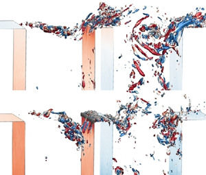
Figure 11. Alternating behaviours of shear layer vortices resonated by the acoustic eigenmode of tandem deep cavities in close arrangement, presented by the temporal evolution of vortex vorticity, vortex structures determined by Q-criterion, coloured with flow swirl and overlapped with wall pressure fluctuations. The four snapshots were selected to be equally spaced within one acoustic period.

Figure 12. Synchronous behaviours of shear layer vortices resonated by the acoustic eigenmode of tandem deep cavities in half-wavelength arrangement, presented by the temporal evolution of vortex vorticity of vortex vorticity and 3-D vortex structures, coloured with flow swirl and overlapped with wall pressure fluctuations.

The second finding relates to the variation in flow characteristics across the different development regions of the turbulent shear layers. In the closely arranged configuration, the flow quantities at the upstream cavity are almost gradually intensified from the linear growth region to the convection region and then the spurious decrement region. However, the flow quantities of the linear growth region at the downstream cavity are most intensified and then gradually attenuated at the convection and spurious decrement regions. We attribute this characteristic to the flow interaction effect, as the initial shear layer oscillation is stronger in the downstream cavity. In contrast, due to the relatively weak flow interaction effect, the flow variation is nearly synchronized in the half-wavelength-arranged tandem deep cavities. The third finding involves the variations in the peak values of the flow parameters. Typically, the peak values tend to occur just below the cavity entrance, a pattern that is supported by the incompressible results. Nonetheless, owing to the acoustic forcing effect, these peak locations can extend further into the cavity volumes within the first two regions and even rise above the cavity entrance within the last region. This suggests a broader flapping motion of shear layers inside the closely spaced tandem deep cavities.

4.3. Kinematics of shear layer vortex structures

To illustrate the dynamic flow behaviours, the vorticity distribution and 3-D vortex structures were extracted from the high-order iLES results at four moments with constant time intervals within one acoustic cycle. Note that the vortex structures were calculated by the Q-criterion, coloured by the quantity of flow swirl and simultaneously displayed with wall pressure fluctuations. Owing to the frequency lock-in mechanism between the acoustic field and flow field, shear layer vortices were continuously formed at the acoustic eigenfrequency; within one acoustic cycle, the shear layer vortex can be classified into three stages, i.e. the formation, convection and impingement regions, which can be qualitatively identified from the time-variant vorticity distribution in all the cavities of figures 11 and 12. In the formation stage, the downward shear layer separated at the leading corner and produced a significant region with intensive vortex vorticity but small spatial scale. In the convection stage, the shear layer vortex became gradually enlarged and transported downstream with alternating rollup and rolldown motions of the shear layer. When coming to the impingement stage, the shear layer vortices impinged into the downstream corner and collapsed into two portions, one portion dropped into the cavity volume and another portion mixed into the mainstream flow, giving rise to separation bubbles along the duct wall.

Such a vortex shedding process has been widely documented in related literature. However, in the current study, the most notable distinction lies in the interactions between the shear layers of the upstream and downstream cavities, which are connected by the shuttled acoustic particle oscillations. For tandem deep cavities in close arrangement, the first-order acoustic eigenmode with antisymmetric feature was resonated at $R{e_{in}} = 1.03 \times {10^5}$, the resultant acoustic particle oscillations shuttled between the tandem cavities can foster the concurrent shear layer vortices into antiphase shedding motion. In the upstream cavity, the vortex structures are mostly concentrated together, yielding energetic vortex system structures with intensive vorticity magnitudes. Throughout a single acoustic cycle, these vortices progress through the formation, convection and impingement stages sequentially. However, at the same moments in the downstream cavity, the shear layer vortices were already reaching the middle point at ${t_1}$; convecting downstream and impinging into the trailing edge from ${t_2}$ to ${t_3}$; new vortices were formed just around the trailing edge at ${t_4}$. Another interesting phenomenon is the presence of 3-D vortex structures that appear more chaotic, enlarged and extended along the cavity entrance. These structures can be attributed to the interactions caused by flow oscillations originating from the upstream cavity. In addition, in accordance with Ho & Kim (Reference Ho and Kim2021), when the shear layer vortices impinge upon the downstream corner, they create a low-pressure region on the trailing surface, which enhances the transfer of maximum energy to the acoustic pressure pulsations.

For the tandem deep cavities in the half-wavelength arrangement, the excited acoustic eigenmode presents a symmetric feature and the resultant acoustic particle oscillations are in phase between the two cavities but out of phase along the main duct. The simultaneous shuttling acoustic particle oscillations foster the concurrent shear layer vortices into almost synchronous shedding motion, as shown in figure 12. The energetic shear layer vortices go through the same stages, i.e. the formation, convection and impingement, simultaneously. A slight discrepancy in the location of the shear layer vortices is attributed to the mainstream flow convection effect. Due to the magnitude discrepancy of excited acoustic pressure pulsations, the variations of the vorticity distribution and vortex structures within each cavity demonstrate different distributions. Relatively, a series of small-scale vortex vorticity are rolled-up and rolled-down by the shear layer separations within the upstream cavity; the vortex structures herein are mostly concentrated together and organized in sequence. Different from upstream cavity, larger-scale vortex structures are identified inside the downstream cavity.

Subsequently, SPOD analysis is implemented to extract dominant vortex structures from the fluctuating velocity fields. Figure 13 illustrates the SPOD results, combined with the frequency spectra, eigenvalues and spatial features of decomposed SPOD modes. This information was obtained directly from the real and imaginary parts of the SPOD modes. The SPOD eigenvalues were normalized to be quantitatively represented as a fraction of the energy contribution to the total flow fluctuation energy, integrated over all SPOD modes and frequencies. As the frequency increases, a tonal peak at 478.5 Hz is observed, which is closely locked onto the eigenfrequency of the first-order acoustic mode. The local peaks at almost twice and three times the harmonics of this fundamental frequency can also be found. The corresponding spatial features of these energetic SPOD modes are illustrated, in which the vertical velocity fluctuations are displayed by removing the low-intensity values. The most intensified velocity fluctuations are formed along the cavity entrances; the global spatial scales become gradually compact with increased frequencies. These alternately positive and negative velocity fluctuations yield coherent vortex structures, which are qualitatively denoted by the annotated arrows. These vortex structures are formed under the Kelvin–Helmholtz instability mechanism when the shear layer separates from the leading edges. As for the first-order mode at 478.5 Hz, a pair of counter-rotating vortex structures are located at the centres of the upstream and downstream cavities, respectively. They align with the oscillation of acoustic particles shuttling between these cavities, resulting in an alternating motion of the concurrent shear layers. Conversely, in the second mode at this frequency, the vortex structures rotate in the same direction. In the high-frequency harmonics, comparable yet slightly attenuated vortex structures are observed within the upstream cavity. More vortex structures appear at the downstream cavity. This contrasting alteration between the upstream and downstream cavities can lead to more intensified velocity variations and shear layer oscillations inside the downstream cavity.

Figure 13. The SPOD analysis of the fluctuating velocity fields within the ducted tandem deep cavities in close arrangement (a) and half-wavelength arrangement (b). The eigenvalue spectra are normalized by the total energy of velocity fluctuations, and the spatial feature of dominant vortex structures are demonstrated.

Figure 13(b) illustrates the outcomes of the SPOD analysis for the tandem deep cavities arranged with a half-wavelength spacing. These results enable the identification of coherent vortex structures linked to the synchronized motion of shear layers. Likewise, the fundamental frequency at 522.5 Hz and its higher-order harmonics, closely aligned with the corresponding acoustic eigenfrequencies, are discernible within the frequency spectrum of the decomposed SPOD modes. The eigenvalues reach remarkable values of 80 %, 30 % and 25 % for these respective modes. This underscores their significant dominance in shaping the synchronous shear layer motions during construction. The corresponding spatial characteristics are portrayed mainly with a sequence of alternating positive and negative velocity fluctuations. As for the most energetic SPOD mode at 522.5 Hz, two co-rotating vortex structures are formed along the entrances of the upstream and downstream cavities, respectively. Under the influence of the acoustic particle oscillations herein, these fluctuations exhibit consistent directions. Differing from the close arrangement, where the coherent vortex structures are situated at the centres of the tandem cavities, the vortex structures in this scenario are instead adhering to the leading and trailing edges of each individual cavity. In this situation, essential fluid streaks are issued to or absorbed from the main duct, yielding a series of vortex pairs along the bottom wall of the main duct. Owing to these coherent vortex structures, the shear layers oscillate in synchrony. Furthermore, aligned with the intensified flow dynamics within the upstream cavity compared with the downstream one, a greater number of vortex structures is observed within the upstream cavity. As the flow progresses towards the main duct and downstream cavity, the velocity fluctuations gradually diminish.

4.4. Aeroacoustic energy transfer mechanism

To reveal the aeroacoustic energy transfer mechanism between the turbulent shear layers and the acoustic eigenmodes, Howe's acoustic analogy (Howe Reference Howe1975) was performed to calculate the acoustic power production by the vortex vorticity. For a homentropic flow, the acoustic power $({P_H})$ is mainly produced by the vorticity convection of vortex structures through the essential measure of the triple product $(\omega \times u) \cdot {u_a}$, which can be formulated by

(4.3)\begin{equation}\langle {P_H}\rangle =- \int {{\rho _0}\langle (\omega \times u) \cdot {u_a}\rangle \,\textrm{d}V} .\end{equation}

The integration of acoustic power over an acoustic cycle permits the determination of the aeroacoustic energy quantity, its positive value represents energy transfer from the flow field to the acoustic field as a production source, while its negative value represents a dissipation sink of the flow field that absorbs energy from the acoustic field. It should be noted that a phase lag of $90\mathrm{^\circ }$ should be considered when determining the acoustic particle velocity. This analogy has been successfully implemented to underpin the aeroacoustic energy production mechanism. Here, by referring to D'Elia, Humbert & Aurégan (Reference D'Elia, Humbert and Aurégan2022), we expand Howe's acoustic analogy with time-averaged and coherent components to see the major contribution source. The time-averaged acoustic power, computed over one time period within a designated fluid volume $(\textrm{d}V)$, was calculated as follows:

(4.4)\begin{equation}\langle {P_H}\rangle =- \int_V {\langle ({F_x}{u_a} + {F_y}{v_a})\rangle \,\textrm{d}V} ,\end{equation}

where $F = {F_x}x + {F_y}y =- {\rho _0}(\omega \times u)$ symbolizes the Coriolis force vector. The symbol $\langle \ast \rangle $ denotes the average operator over one acoustic cycle. With triple decomposition but neglecting the random term, the total vorticity and velocity are written as $\omega = ({\varOmega _0} + \omega ^{\prime})z$, $u = ({U_0} + u^{\prime})x + ({V_0} + v^{\prime})y$, the acoustic article velocity is also written in a vector style as ${u_a} = {u_a}x + {v_a}y$. Subsequently, the inner product of average terms and the coherent term of the Coriolis force vector within a cycle can be respectively disregarded. Thus, each component of the vector $\boldsymbol{F}$ can be divided into two contributions, and their inner product with the acoustic velocity yields four acoustic power terms as follows:

(4.5ad) \begin{align}{\hat{P}_{1\_1}} &= \langle({\rho _0}{\varOmega _0}v^{\prime}){u_a}\rangle,\quad {\hat{P}_{1\_2}} = \langle({\rho _0}\omega ^{\prime}{V_0}){u_a}\rangle,\quad {\hat{P}_{2\_1}} = \langle- ({\rho _0}{\varOmega _0}u^{\prime}){v_a}\rangle,\notag\\ {\hat{P}_{2\_2}} &=\langle- ({\rho _0}\omega ^{\prime}{U_0}){v_a}\rangle.\end{align}

Through this decomposition, we delineate the contribution maps of each term to the total aeroacoustic energy transfer within one acoustic cycle, as shown in figures 14 and 15 for the closely arranged and half-wavelength-arranged tandem deep cavities, respectively. The blanked areas with small values were removed to highlight the major sources and sinks. In addition, we also normalized the acoustic power by a reference value with ${P_{ref}} = {\rho _0}{c_0}|{u_a}{|^2}/2$, the legends for each panel were also adjusted.

Figure 14. Aeroacoustic energy transfer mechanism between turbulent shear layers and out-of-phase acoustic eigenmodes inside tandem deep cavities with close arrangement.

Figure 15. Aeroacoustic energy transfer mechanism between turbulent shear layers and in-phase acoustic eigenmodes inside tandem deep cavities with half-wavelength arrangement.

For the acoustic power generated by the horizontal Coriolis force, the ${\hat{P}_{1\_1}}$ component contributes more than ${\hat{P}_{1\_2}}$, this is evident for both configurations. In ${\hat{P}_{1\_1}}$, the mean vorticity ${\varOmega _0}$ presents pronounced amplitudes along the cavity entrances, especially at the corners of the deep cavities. When considering the vertical velocity fluctuation, we observe that, due to its minimal near-wall variations, the acoustic power contribution here is effectively filtered out. The extensive regions of intensified acoustic power values situated within the cavity mouths are attributed to two sources: the hydrodynamic convection from cavity to cavity, and the horizontal component of the acoustic particle velocity. In closely arranged tandem deep cavities, the oscillations of acoustic particle are out of phase between the upstream and downstream cavities. This triggers an interesting dynamic, where the direction of the acoustically induced particle motion counteracts the direction of convective transport between the cavities. This mechanism gives rise to distinct sound generation and absorption regions in the upstream and downstream cavities, respectively. However, in the half-wavelength arrangement, the standing waves in the upstream and downstream cavities are in phase, leading to similar spatial distributions of the horizontal acoustic speed. The pairing of sound sources and sinks observed in the previous set-up is not present. Regarding the ${\hat{P}_{1\_2}}$ component, the areas contributing to acoustic power are largely equivalent for both arrangements. Two crucial observations merit attention. Initially, the confinement of the vertical velocity around the cavity corners results in a corresponding limitation of the acoustic power distribution within the same spatial region. Secondly, vorticity fluctuations lack phase correlation with horizontal acoustic particles, only producing irregularly scattered acoustic sources and sinks at locations where the horizontal acoustic particle velocity is considerable.

As for acoustic power generated by the vertical Coriolis force, the ${\hat{P}_{2\_1}}$ term presents an intriguing scenario, which is characterized by stripe-shaped regions within the cavity entrance. These striped regions are a consequence of streamwise vortex shedding, wherein essential vorticity becomes coupled with the constrained fluctuations of streamwise velocity within the shear layer. When examining the term ${\hat{P}_{2\_2}}$, it becomes evident that this term exhibits the most pronounced spatial distribution characteristics of acoustic power. This feature is a result of the significant magnitudes of the coherent vorticity $\omega ^{\prime}$, and the fact that the horizontal velocity ${U_0}$ exceeds ${V_0}$, which further enhances the production of acoustic power. As a result, this dominance leads to the magnitude of the ${\hat{P}_{2\_2}}$ term being approximately one order of magnitude higher than other terms, with the exception of specific regions where other contributions may surpass it. These findings are also consistent with the experimental results presented in D'Elia et al. (Reference D'Elia, Humbert and Aurégan2022). The spatial distribution of this acoustic power contribution exhibits a high degree of consistency across both configurations: the area from the upstream corner of the cavity to the mid–lower part consistently acts as an acoustic sink, while the region from the mid–upper part to the downstream corner functions as an acoustic source. Undoubtedly, the coherent vorticity fluctuations dominate the distribution of acoustic power production, these energetic areas are closely associated with the downward convection, vertical flapping and rolling-up motions of the turbulent shear layers. It should be noted that, even though the spatial distributions of aeroacoustic power in the upstream and downstream cavities are similar, there is a 180° phase difference in the instantaneous acoustic power distributions for the closely arranged configuration, which is attributed to the phase difference between the standing waves within two cavities.

Another explanation on the aeroacoustic energy transfer is from the view on phase-dependent variations of the acoustic source or sink. During the initial half of the acoustic cycle, local high-pressure stagnation zones induced by shear layer fluctuations near the upstream corner, in conjunction with separated flows, will yield compressive (high-pressure) sound waves within the cavity. Simultaneously, the negative acoustic pressure gradient along cavity depth prompts acoustic particles to uniformly move towards the cavity endplate. Consequently, the downward clockwise shedding vortices carrying negative vorticity interacted with the negative acoustic particle velocity, making this region act as an acoustic sink. This interaction transfers aeroacoustic energy from the sound field to the flow field and subsequently facilitates the shed vortex as well as the shear layer. In the latter half of the acoustic cycle, interactions between large-scale vortices and the downstream corner lead to the creation of additional rarefaction or low-pressure sound waves. These waves eventually interfere with waves reflected from the cavity bottom. At this juncture, the positive acoustic pressure gradient along the cavity depth stimulates the acoustic particles to uniformly move towards the cavity opening. As a result, the negative vorticity region produced by the large-scale vortices and deflection of the shear layer towards the mainstream due to twisting–suction effect (Elder Reference Elder1980), through their product with the positive acoustic particle velocity, cause this region to serve as an acoustic source. This interaction transfers hydrodynamic energy from the flow field to the sound field, thereby ensuring energy conservation for self-sustained resonant oscillations. These findings were also indicated in the work of Dai, Jing & Sun (Reference Dai, Jing and Sun2015), in which a force-balance relationship between the cavity opening and the cavity bottom was established when the grazing shear layer coupled with the cavity acoustic eigenmode.

5. Decoupled aeroacoustic simulation

This section proposes a decoupled aeroacoustic simulation strategy to further reveal the coherent perturbations of turbulent shear layers produced purely by external acoustic forcing. Two effects should be taken into consideration to improve the acoustic simulation accuracy, i.e. the flow convection effect and the turbulence interaction effect, which can dissipate or amplify the acoustic fields nonlinearly (Gikadi, Föller & Sattelmayer Reference Gikadi, Föller and Sattelmayer2014; Du et al. Reference Du, Holmberg, Karlsson and Åbom2016). This can be implemented by solving the LNSEs upon the mean flow field and considering the flow velocity, pressure, density and especially turbulent viscosity, as known quantities. By solving compressible LNSEs on the steady-state turbulent flow but with periodic acoustic forcing, the turbulent flow induced acoustic scattering and acoustically excited fluid perturbations can be determined.

5.1. Numerical set-up

The decoupled aeroacoustic simulation is classified into three major steps, the first obtains the steady-state or time-averaged flow field from flow simulation, the second maps the flow information from the fluid mesh to the acoustic mesh and the third numerically solves the compressible LNSEs. Here, the shear stress transport (SST) turbulence model is used to determine the steady-state turbulent flow within the tandem deep cavities, as much less numerical diffusion and better prediction of the eddy viscosity can be achieved. Note that the time-averaged flow fields from the previous LES results were not used as a base flow, as they have been already excited by the acoustic resonance oscillations and superimposed with the turbulence fluctuations. The SST-simulated mean flow quantities containing the turbulent viscosity $({\mu _\tau })$ were interpolated from the flow mesh onto the acoustic mesh during the mapping step. The LNSEs around the mapped base flow were numerically solved with a generalized minimal residual solver (Saad & Schultz Reference Saad and Schultz1986) and a Galerkin/least-square finite element (FE) stabilization scheme. A gradient term stabilization was introduced to suppress the Kelvin–Helmholtz instabilities by the reactive terms of the LNSEs. The numerical set-up is depicted in figure 16(a), where two configurations, one with a close arrangement and the other with a half-wavelength arrangement, were established. The boundary conditions for their flow simulations were kept consistent with the previous LESs. To discretize the fluid domain and acoustic domain, two sets of meshes were generated. Triangular elements and boundary layer elements were adopted within the computational domains. For flow meshes, the thickness of the first cell was determined such that y + value was almost close to 1, and approximately 0.2 and 0.5 million elements were finally generated within the two configurations. For the acoustic mesh, approximately10 nodes per acoustic wavelength were set to describe the acoustic wave propagation without numerical dissipation. The frequency range of the incident acoustic waves was set to 200–3500 Hz with a step of $\Delta f = 10\ \textrm{Hz}$, yielding a maximum element size of 0.01 mm with additional mesh refinement around the cavity entrances. The number of acoustic meshes reached 0.06 million for one configuration and 0.08 million for the other configuration. Note that the incident acoustic waves were planar waves, as their frequencies were below the cutoff frequency of the main duct. During acoustic simulations, the acoustic source regions were added at the two cavity endplates and harmonic pressure forcing was set as a source term to LNSEs. This was implemented by writing an expression into the LNSEs to define the direction, amplitude, frequency, phase and wavenumber information. For the close arrangement, a phase difference of $180\mathrm{^\circ }$ was applied between the two endplate acoustic sources, therefore out-of-phase acoustic forcing was created and acted on the concurrent shear layers; for the half-wavelength arrangement, in-phase acoustic forcing was created at the two cavity endplates. Besides, regions with a perfectly matched layer (PML) were also set at the inlet, outlet and cavity endplates to dissipate the incoming acoustic waves and prevent acoustic wave reflections. Here, PML imposes a complex-valued coordinate transformation (frequency domain) or inverse Laplace transformation (time domain) to satisfy the Sommerfeld radiation condition that can effectively maintain its wave impedance and eliminate wave reflections (Johnson Reference Johnson2021). An adiabatic condition was applied to the wall surface to make the temperature perturbation at the walls consistent with the pressure perturbations using the Neumann condition. To save computational cost, the acoustic simulations were conducted in the frequency domain rather than the time domain.

Figure 16. Numerical set-up (a) for the decoupled aeroacoustic simulation using linearized Navier–Stokes equations with out-of-phase (b) and in-phase (c) external acoustic forcing imposed on the closely arranged and half-wavelength-arranged tandem deep cavities, respectively. The enlarged panels highlight the acoustic scattering around the cavity entrances.

Figures 16(b) and 16(c) illustrate the successfully applied acoustic forcing fields to the tandem deep cavities, their frequencies and intensities were kept in consistency with the abovementioned experimental results. After the incident acoustic waves were generated at the cavity endplates, they propagate across the turbulent shear layers, enter the main duct and radiate outside through the PMLs. Four snapshots with different phases were utilized for demonstration; out-of-phase acoustic forcing was observed for the closely arranged configuration and in-phase acoustic forcing was for the half-wavelength configuration, confirming that the present LNSE model can mimic the internal acoustic forcing excited by the acoustic eigenmodes. Furthermore, upon closer examination of the isoline patterns within the highlighted panels, we observed a sequence of acoustic pulsations surrounding the entrances of the cavities and the downstream wall surfaces. These observations suggest the presence of acoustic scattering phenomena. These locations were nearly coincident with the vortices within the shear layers, providing confirmation that the current decoupled aeroacoustic simulations successfully captured the interactions between the stable turbulent shear layers and the external acoustic forcing.

To further confirm the present results, two measures, i.e. coherent kinetic energy $({\hat{G}_k})$ and coherent vorticity convection $({\hat{G}_\omega })$, are used to delineate the linear response of the turbulent shear layers to the external acoustic forcing by referring to Boujo et al. (Reference Boujo, Bauerheim and Noiray2018)

(5.1a,b)\begin{equation}{\hat{G}_k} = \frac{1}{{u_{ac}^2}}\left( {\iint_{{\Omega_c}} {({{\tilde{u}}^2} + {{\tilde{v}}^2})\,\textrm{d}\kern0.06em x\,\textrm{d}y} } \right)\!,\quad {\hat{G}_\omega } = \frac{1}{{{u_{ac}}}}\left( {\iint_{{\Omega_c}} {({{\tilde{\omega }}_z}\bar{U})\,\textrm{d}\kern0.06em x\,\textrm{d}y} } \right)\!,\end{equation}

where ${\varOmega _c}$ is the integrated domain spanning the streamwise extension of each cavity, ${\tilde{\omega }_z} = {\partial _x}\tilde{v} - {\partial _y}\tilde{u}$ is the spanwise vorticity of the coherent response. The first measure is useful to evaluate the kinetic energy of the acoustically excited fluid perturbation, the second is associated with the Coriolis force and represents the acoustic power production. Globally, both measures exhibit substantial amplification followed by dissipation as the frequency of the applied acoustic forcing increases, as shown in figure 17. For the closely arranged configuration, we observe two distinct peaks near 550 Hz and 1100 Hz, whereas for the half-wavelength-arranged configuration, two peaks are identified in close proximity to 620 Hz and 1270 Hz. Obviously, the first peaks can be related to the resonated acoustic eigenmodes but are overpredicted, and the second peaks are harmonics of the first peaks. The overprediction can be attributed to the influence of convective flow effects. Typically, turbulence interaction effects tend to shift resonance towards lower frequencies, while convective flow effects have the opposite effect, pushing it towards higher frequencies (Meliga Reference Meliga2017). This phenomenon also accounts for the frequency difference observed between the two tandem cavities. The spatial patterns of coherent perturbations within the shear layers will be examined in the upcoming section, focusing on these two dominant frequencies as indicated by the LNSE results.

Figure 17. Linear response of turbulent shear layers to the harmonic acoustic forcing: (a) coherent kinetic energy by out-of-phase acoustic forcing in closely arranged tandem deep cavities; (b) coherent kinetic energy by in-phase acoustic forcing in half-wavelength-arranged tandem deep cavities; (c) coherent vorticity convection by out-of-phase acoustic forcing; and (d) coherent vorticity convection by in-phase acoustic forcing. The frequency range of incident acoustic wave varied between 100 and 3000 Hz with a frequency interval of 10 Hz. The broad frequency bands from the compressible iLES simulations are also annotated for comparison.

5.2. Coherent perturbations of turbulent shear layers

The linear response of the steady-state turbulent shear layers to harmonic acoustic forcing is characterized in terms of the phase-dependent evolution of streamwise velocity perturbation and the superimposed streamlines, as shown in figure 18. Noting that the phase variation gives rise to different acoustic pressure gradients acting on the shear layers. Globally, the response is localized within the shear layer and downstream boundary layer, which is reasonable with the large flow gradient and turbulent viscosity here. Distinctive wavepacket structures originate from the cavity entrances, and they exhibit a streamwise expansion along the main duct while simultaneously contracting vertically as they approach the cavity's end. Simultaneously, weak velocity perturbations are generated at the upstream cavity corner and amplified when transported towards the downstream corner by the streamwise convecting shear layers; this process is a typical response of shear layer instability.

Figure 18. Phase-dependent evolution of coherent streamwise velocity perturbation $(\tilde{u})$ and coherent energy density $({G_k})$ by (a,c) out-of-phase acoustic forcing of closely arranged tandem deep cavities, and (b,d) in-phase acoustic forcing of half-wavelength-arranged tandem deep cavities.

The present study can be discerned through a comparative analysis between the two tandem cavities in different arrangements. In the case of close arrangement, application of out-of-phase acoustic forcing resulted in opposing yet notably intensified velocity perturbations at the downstream cavity. Additionally, distinctive vortex structures with varying rotation directions were observed. This phenomenon supported the iLES finding with a more expanded shear layer within the downstream cavity. Such amplification can be confirmed in figure 18(c), in which the coherent energy density was calculated and plotted along the cavity entrances, almost one level higher energy density can be found along the downstream cavity than the upstream cavity. As for the half-wavelength arrangement, the applied in-phase acoustic forcing yielded similar but slightly intensified velocity perturbations at the downstream cavity, and the rotation directions of vortex structures were also same. Here, the discrepancy between the LNSE result and iLES result is attributed to the downstream acoustic intensity; as in iLES, the resonance intensity is quite attenuated compared with the upstream cavity. When coming to the phase-dependent evolution process of the coherent vortex structures, the number and spatial scale of the coherent vortex structures within the cavity entrances are vary periodically.

Under the influence of acoustic forcing, a large-scale vortex structure initially occupies the cavity entrance but evolves into two smaller-scale vortex structures in the subsequent phase. Subsequently, they reconfigure into a single large-scale vortex structure, characterized by streamwise displacement and an opposite rotation direction. This process can induce a streamwise growth of energy density from the upstream corner but with fluctuations when approaching the downstream corner. Besides, alternating variations of the coherent vortex structures and energy density can be identified between the two cavities in close arrangement, but synchronous variation of the half-wavelength-arranged configuration, consolidating the coherent perturbations of the turbulent shear layers.

Figures 19 and 20 illustrate the phase-dependent evolution of the synthetic streamwise velocity, synthetic spanwise vorticity and shear layer momentum thickness in response to the external acoustic forcing acting on the tandem deep cavities. These three quantities took the time-averaged flow fields into consideration, and can demonstrate the dynamic responses of mean flow to the periodic acoustic forcing. In figure 19(a) for the tandem deep cavities in close arrangement, snapshots of streamwise velocity, spanwise vorticity and superimposed velocity streamlines depict the formation, convection and collapse processes of the coherent vortex structures within the two cavity entrances. A phase difference between the two cavities demonstrates the occurrence of alternating motion. This can be further explored by the variations of shear layer momentum thickness, as plotted in figure 20(a). Periodic oscillations of the shear layer can be observed by tracing the phase-dependent locations of the maximum thickness, indicating a periodic flapping motion of the turbulent concurrent shear layers. During the first half-acoustic period, the maximum thickness of the upstream shear layer gradually increased and the corresponding locations gradually transported and approached the downstream wall surfaces; during the second half-period, after the shear layer impinging on the downstream wall surface, the maximum thickness gradually decreased and their locations gradually approached the upstream trailing edge. When looking into the downstream cavity, the shear layer momentum thickness was significantly amplified with larger values. However, the evolution process demonstrates a phase lag with the upstream shear layer. As the shear layer has already impinged on the trailing edge within the first half of an acoustic period; while in the second half, the locations of maximum thickness appeared almost at the centre of the cavity entrance. Such phase-differentiated shear layer perturbations by the out-of-phase acoustic forcing are in consistency with the alternating resonance behaviour.

Figure 19. Phase-dependent evolution of coherent shear layer perturbations inside tandem deep cavities, presented by synthetic streamwise velocity $(\tilde{u} + \bar{U})$ and synthetic spanwise vorticity $({\tilde{\omega }_z} + {\bar{\varOmega }_z})$: (a) with out-of-phase acoustic forcing of the close arrangement; (b) with in-phase acoustic forcing of the half-wavelength arrangement.

Figure 20. Phase-dependent evolution of coherent shear layer perturbations, represented by momentum thickness: (a) closely arranged and (b) half-wavelength-arranged tandem deep cavities.

In figure 20(b), phase-similar shear layer perturbations by the in-phase acoustic forcing are found in the half-wavelength arrangement, which are consistent with the abovementioned synchronous resonance behaviour of the turbulent shear layers. Even the momentum thickness demonstrates a slight intensification at the downstream cavity; the locations of the maximum thicknesses are close in each cavity at all of the four phases. Two kinds of flow structures are also found from LNSE results, i.e. the accompanying recirculation zone below the shear layer vortex structures and the separation bubble along the downstream main duct wall surface. The recirculation zone is formed by the turbulent entrainment effect and its oscillation is driven by the shear layer vortices. Regarding the separation bubble, it originated when the downstream shear layer vortex structures impinged upon the downstream corner and subsequently amplified, convecting along the main duct wall surface. Similar flow structures, characterized by recirculation zones and separation bubbles, can also be observed in Wang et al. (Reference Wang, Deng, Mao, He and Liu2020) and Ho & Kim (Reference Ho and Kim2021). This separation bubble was also attributed to the divergence of Reynolds stress, which can lead to an increase in the thickness of the shear layer (Mantič-Lugo & Gallaire Reference Mantič-Lugo and Gallaire2016). Now, focusing on the half-wavelength arrangement, as shown in figure 19(b), the flow structures resulting from in-phase acoustic forcing bear a resemblance to the previously mentioned findings. These include coherent vortex structures along the cavity entrances accompanied by recirculation zones inside the cavity volumes and separation bubbles along the downstream main duct wall surface. Nonetheless, two notable differences can be observed. First, there is a synchronous evolution process between the two tandem cavities, which is consistent with the iLES results. Second, there is the appearance of an additional separation bubble originating from the upstream cavity corner. This is logical as these two cavities are spaced further apart.

6. Conclusions

The resonance mechanism and coherent perturbations of turbulent shear layers inside tandem deep cavities undergoing internal and external acoustic forcing were explored by solving the nonlinear and linearized Navier–Stokes equations, respectively. Implicit-LES (iLES) through a high-order spectral/hp element method was implemented to directly solve the compressible Navier–Stokes equations; thus fully coupled aeroacoustic fields inside the tandem deep cavities with close and half-wavelength arrangements were respectively acquired, in which the acoustic eigenmodes were significantly excited at high Reynolds numbers $(R{e_{in}} = {O}({10^5}))$but low Mach numbers $(M{a_{in}} < 0.15)$. As a complementary strategy, an acoustic finite-element method was performed to solve the LNSEs to acquire the decoupled aeroacoustic fields. The coherent perturbations of turbulent concurrent shear layers in response to the external acoustic forcing can be determined. In sum, the major findings are provided as below: first, alternating behaviour of shear layer vortices between tandem deep cavities in close arrangement was found, resonated by the out-of-phase acoustic eigenmodes, yielding significantly amplified shear layer oscillations inside the downstream cavity entrance; the maximum growth rate of the shear layer momentum thickness reached approximately $\vartheta = 0.12$, in accordance with high-amplitude resonance regime. Conversely, a synchronous behaviour of shear layer vortices was observed within tandem deep cavities arranged at half-wavelength intervals. These cavities resonated due to their in-phase acoustic eigenmodes. Another distinction involves the dissipation of shear layer oscillations along the entrance of the downstream cavity. Next, by conducting spectral proper orthogonal analysis of iLES-simulated velocity fields, the dominant vortex structures were extracted: counter-rotating vortex pairs was identified at the entrances of closely arranged tandem deep cavities, while co-rotating vortex structures were identified for the half-wavelength-arranged tandem deep cavities. Third, through the calculation of acoustic power generated by the Coriolis force acting on vortex vorticity using Howe's sound-vortex analogy, we were able to establish the aeroacoustic energy transfer between flow fields and acoustic fields. The component $\langle - ({\rho _0}\omega ^{\prime}{U_0}){v_a}\rangle $ contributes significantly to the overall acoustic power production. During the initial half of the acoustic period, the shear layer vortices are formed and evolve, leading to the dissipation of acoustic energy. In the latter half of the acoustic period, the shear layer interacts with the trailing corners, resulting in significant acoustic power generation and the transfer of energy to the acoustic waves. Finally, the LNSEs model was employed to predict the flow–acoustic resonance between turbulent shear layers with external acoustic forcing. The overprediction of peak frequencies may be attributed to the convective flow effect rather than the turbulence dissipation effect. The linear response of turbulent shear layers agrees well with the compressible iLES results. Additional detailed information regarding wall-attached separation bubbles resulting from the streamwise amplification of the shear layer is captured by using the present LNSEs model. Furthermore, the recirculation zones beneath, caused by the downward dissipation of the shear layer vortices, are captured well.

Funding

The authors gratefully acknowledge financial support for this study from the National Natural Science Foundation of China (grant nos. 12172221 and 12372274), and the Natural Science Foundation of Shanghai (grant no. 23ZR1433500).

Declaration of interests

The authors report no conflict of interest.

References

Abdelmwgoud, M., Shaaban, M. & Mohany, A. 2020 Flow dynamics and azimuthal behavior of the self-excited acoustic modes in axisymmetric shallow cavities. Phys. Fluids 32 (11), 115109.CrossRefGoogle Scholar
Ahuja, K.K. & Mendoza, J. 1995 Effects of cavity dimensions, boundary layer, and temperature on cavity noise with emphasis on benchmark data to validate computational aeroacoustic codes. No. NAS 1.26: 4653.Google Scholar
Alenius, E., Åbom, M. & Fuchs, L. 2015 Large eddy simulations of acoustic-flow interaction at an orifice plate. J. Sound Vib. 345, 162177.CrossRefGoogle Scholar
Barbieri, R. & Barbieri, N. 2006 Finite element acoustic simulation based shape optimization of a muffler. Appl. Acoust. 67 (4), 346357.CrossRefGoogle Scholar
Boujo, E., Bauerheim, M. & Noiray, N. 2018 Saturation of a turbulent mixing layer over a cavity: response to harmonic forcing around mean flows. J. Fluid Mech. 853, 386418.CrossRefGoogle Scholar
Bourquard, C., Faure-Beaulieu, A. & Noiray, N. 2021 Whistling of deep cavities subject to turbulent grazing flow: intermittently unstable aeroacoustic feedback. J. Fluid Mech. 909, A19.CrossRefGoogle Scholar
Bruggeman, J.C., Hirschberg, A., van Dongen, M.E., Wijnands, A.P. & Gorter, J. 1991 Self-sustained aero-acoustic pulsations in gas transport systems: experimental study of the influence of closed side. J. Sound Vib. 150 (3), 371393.CrossRefGoogle Scholar
Cantwell, C.D., et al. 2015 Nektar++: an open-source spectral/hp element framework. Comput. Phys. Commun. 192, 205219.CrossRefGoogle Scholar
Dai, X. & Aurégan, Y. 2018 A cavity-by-cavity description of the aeroacoustic instability over a liner with a grazing flow. J. Fluid Mech. 852, 126145.CrossRefGoogle Scholar
Dai, X., Jing, X. & Sun, X. 2015 Flow-excited acoustic resonance of a Helmholtz resonator: discrete vortex model compared to experiments. Phys. Fluids 27 (5), 057102.CrossRefGoogle Scholar
D'Elia, M.E., Humbert, T. & Aurégan, Y. 2022 Linear investigation of sound-flow interaction along a corrugated plate. J. Sound Vib. 534, 117048.CrossRefGoogle Scholar
Doak, P.E. 1989 Momentum potential theory of energy flux carried by momentum fluctuations. J. Sound Vib. 131 (1), 6790.CrossRefGoogle Scholar
Du, L., Holmberg, A., Karlsson, M. & Åbom, M. 2016 Sound amplification at a rectangular T-junction with merging mean flows. J. Sound Vib. 367, 6983.CrossRefGoogle Scholar
Elder, S.A. 1980 Forced oscillations of a separated shear layer with application to cavity flow-tone effects. J. Acoust. Soc. Am. 67 (3), 774781.CrossRefGoogle Scholar
Faure-Beaulieu, A., Pedergnana, T. & Noiray, N. 2023 a Self-sustained azimuthal aeroacoustic modes. Part 2. Effect of a swirling mean flow on the modal dynamics. J. Fluid Mech. 971, A22.CrossRefGoogle Scholar
Faure-Beaulieu, A., Xiong, Y., Pedergnana, T. & Noiray, N. 2023 b Self-sustained azimuthal aeroacoustic modes. Part 1. Symmetry breaking of the mean flow by spinning waves. J. Fluid Mech. 971, A21.CrossRefGoogle Scholar
Forestier, N., Jacquin, L. & Geffroy, P. 2003 The mixing layer over a deep cavity at high-subsonic speed. J. Fluid Mech. 475, 101145.CrossRefGoogle Scholar
Gikadi, J., Föller, S. & Sattelmayer, T. 2014 Impact of turbulence on the prediction of linear aeroacoustic interactions: acoustic response of a turbulent shear layer. J. Sound Vib. 333 (24), 65486559.CrossRefGoogle Scholar
Hartmann, R. & Houston, P. 2006 Symmetric interior penalty DG methods for the compressible Navier–Stokes equations I: method formulation. Intl J. Numer. Anal. Model. 3 (1), 120.Google Scholar
Hirschberg, A. & Rienstra, S.W. 2004 An Introduction to Aeroacoustics. Eindhoven University of Technology, 31.Google Scholar
Ho, Y.W. & Kim, J.W. 2021 A wall-resolved large-eddy simulation of deep cavity flow in acoustic resonance. J. Fluid Mech. 917, A17.CrossRefGoogle Scholar
Howe, M.S. 1975 Contributions to the theory of aerodynamic sound, with application to excess jet noise and the theory of the flute. J. Fluid Mech. 71 (4), 625673.CrossRefGoogle Scholar
Johnson, S.G. 2021 Notes on perfectly matched layers (PMLs). Preprint, arXiv:2108.05348.Google Scholar
Karniadakis, G. & Sherwin, S.J. 2005 Spectral/hp Element Methods for Computational Fluid Dynamics. Oxford University Press.CrossRefGoogle Scholar
Kirby, R.M. & Sherwin, S.J. 2006 Stabilisation of spectral/hp element methods through spectral vanishing viscosity: application to fluid mechanics modelling. Comput. Meth. Appl. Mech. Engng 195 (23–24), 31283144.CrossRefGoogle Scholar
Larchevêque, L., Sagaut, P., , T.H. & Comte, P. 2004 Large-eddy simulation of a compressible flow in a three-dimensional open cavity at high Reynolds number. J. Fluid Mech. 516, 265301.CrossRefGoogle Scholar
Lumley, J.L. 2007 Stochastic Tools in Turbulence. Courier Corporation.Google Scholar
Mantič-Lugo, V. & Gallaire, F. 2016 Self-consistent model for the saturation mechanism of the response to harmonic forcing in the backward-facing step flow. J. Fluid Mech. 793, 777797.CrossRefGoogle Scholar
Meliga, P. 2017 Harmonics generation and the mechanics of saturation in flow over an open cavity: a second-order self-consistent description. J. Fluid Mech. 826, 503521.CrossRefGoogle Scholar
Mengaldo, G., De Grazia, D., Moxey, D., Vincent, P.E. & Sherwin, S.J. 2015 Dealiasing techniques for high-order spectral element methods on regular and irregular grids. J. Comput. Phys. 299, 5681.CrossRefGoogle Scholar
Mengaldo, G., Moxey, D., Turner, M., Moura, R.C., Jassim, A., Taylor, M., Peiro, J. & Sherwin, S. 2021 Industry-relevant implicit large-eddy simulation of a high-performance road car via spectral/hp element methods. SIAM Rev. 63 (4), 723755.CrossRefGoogle Scholar
Moura, R.C., Aman, M., Peiró, J. & Sherwin, S.J. 2020 Spatial eigenanalysis of spectral/hp continuous Galerkin schemes and their stabilisation via DG-mimicking spectral vanishing viscosity for high Reynolds number flows. J. Comput. Phys. 406, 109112.CrossRefGoogle Scholar
Moura, R.C., Sherwin, S.J. & Peiró, J. 2015 Linear dispersion–diffusion analysis and its application to under-resolved turbulence simulations using discontinuous Galerkin spectral/hp methods. J. Comput. Phys. 298, 695710.CrossRefGoogle Scholar
Moxey, D., et al. 2020 Nektar++: enhancing the capability and application of high-fidelity spectral/hp element methods. Comput. Phys. Commun. 249, 107110.CrossRefGoogle Scholar
Nakiboğlu, G., Belfroid, S.P.C., Golliard, J. & Hirschberg, A. 2011 On the whistling of corrugated pipes: effect of pipe length and flow profile. J. Fluid Mech. 672, 78108.CrossRefGoogle Scholar
Nakiboğlu, G., Manders, H.B.M. & Hirschberg, A. 2012 Aeroacoustic power generated by a compact axisymmetric cavity: prediction of self-sustained oscillation and influence of the depth. J. Fluid Mech. 703, 163191.CrossRefGoogle Scholar
Okuyama, K., Tamura, A., Takahashi, S., Ohtsuka, M. & Tsubaki, M. 2012 Flow-induced acoustic resonance at the mouth of one or two side branches. Nucl. Engng Des. 249, 154158.CrossRefGoogle Scholar
Rowley, C.W., Colonius, T. & Basu, A.J. 2002 On self-sustained oscillations in two-dimensional compressible flow over rectangular cavities. J. Fluid Mech. 455, 315346.CrossRefGoogle Scholar
Saad, Y. & Schultz, M.H. 1986 GMRES: a generalized minimal residual algorithm for solving nonsymmetric linear systems. SIAM J. Sci. Comput. 7 (3), 856869.CrossRefGoogle Scholar
Schmidt, O.T. & Colonius, T. 2020 Guide to spectral proper orthogonal decomposition. AIAA J. 58 (3), 10231033.CrossRefGoogle Scholar
Shaaban, A.A. & Ziada, S. 2018 a Fully developed building unit cavity source for long multiple shallow cavity configurations. Phys. Fluids 30 (8), 086105.CrossRefGoogle Scholar
Shaaban, A.A. & Ziada, S. 2018 b Acoustic response of multiple shallow cavities and prediction of self-excited acoustic oscillations. ASME J. Fluids Engng 140 (9), 091203.CrossRefGoogle Scholar
Tadmor, E. 1989 Convergence of spectral methods for nonlinear conservation laws. SIAM J. Numer. Anal. 26 (1), 3044.CrossRefGoogle Scholar
Thornber, B. & Drikakis, D. 2008 Implicit large-eddy simulation of a deep cavity using high-resolution methods. AIAA J. 46 (10), 26342645.CrossRefGoogle Scholar
Tonon, D., Hirschberg, A., Golliard, J. & Ziada, S. 2011 a Aeroacoustics of pipe systems with closed branches. Intl J. Aeroacoust. 10 (2–3), 201275.CrossRefGoogle Scholar
Tonon, D., Willems, J.F.H. & Hirschberg, A. 2011 b Self-sustained oscillations in pipe systems with multiple deep side branches: prediction and reduction by detuning. J. Sound Vib. 330 (24), 58945912.CrossRefGoogle Scholar
Towne, A., Schmidt, O.T. & Colonius, T. 2018 Spectral proper orthogonal decomposition and its relationship to dynamic mode decomposition and resolvent analysis. J. Fluid Mech. 847, 821867.CrossRefGoogle Scholar
Unnikrishnan, S. & Gaitonde, D.V. 2016 Acoustic, hydrodynamic and thermal modes in a supersonic cold jet. J. Fluid Mech. 800, 387432.CrossRefGoogle Scholar
Wang, P., Deng, Y., Mao, Q., He, C. & Liu, Y. 2020 Phase-locking particle image velocimetry measurements of acoustic-driven flow interactions between tandem deep cavities. Phys. Fluids 32 (12), 125115.CrossRefGoogle Scholar
Yamouni, S., Sipp, D. & Jacquin, L. 2013 Interaction between feedback aeroacoustic and acoustic resonance mechanisms in a cavity flow: a global stability analysis. J. Fluid Mech. 717, 134165.CrossRefGoogle Scholar
Ziada, S., Bolduc, M. & Lafon, P. 2017 Flow-excited resonance of diametral acoustic modes in ducted rectangular cavities. AIAA J. 55 (11), 38173830.CrossRefGoogle Scholar
Ziada, S. & Bühlmann, E.T. 1992 Self-excited resonances of two side-branches in close proximity. J. Fluids Struct. 6 (5), 583601.CrossRefGoogle Scholar
Ziada, S. & Lafon, P. 2014 Flow-excited acoustic resonance excitation mechanism, design guidelines, and counter measures. Appl. Mech. Rev. 66 (1), 010802.CrossRefGoogle Scholar
Figure 0

Figure 1. (a) Schematic of flow–acoustic interaction within tandem deep cavities; (b) contour plots of the acoustic eigenmodes corresponding to the four configurations with ${\rm \pi} = 1,\; 4,\; 8,\; 16$; the first row represents the first-order mode and the second row represents the second-order mode.

Figure 1

Figure 2. (a) Experimental set-up of acoustic measurements for tandem deep cavities; (b) plots of r.m.s. of wall pressure fluctuation as a function of mainstream Reynolds number, the selected monitor is locating at the endplate of upstream deep cavity; (c) plots of SPSLs; (d) spectrogram for the four configurations with ${\rm \pi} = 1,\; 4,\; 8,\; 16$.

Figure 2

Figure 3. Waveform identification (a), spatio-temporal evolution of the flow-excited acoustic pulsations along the ducted tandem deep cavities with ${\rm \pi} = 1$, $R{e_{in}} = 1.03 \times {10^5}$ (b) and $R{e_{in}} = 1.29 \times {10^5}$ (b); and ${\rm \pi} = 8$, $R{e_{in}} = 1.18 \times {10^5}$ (d,e). The white square symbols in (a) and (d) denote the sensor locations; in (b,c) and (e), the abscissa denotes the sensor number, starting at the endplate of the upstream cavity, the time intervals were sampled equally within one acoustic period corresponding to the fundamental frequency.

Figure 3

Table 1. Flow conditions for numerical simulations using high-order spectral/hp element method. Here, DOF denotes degree of freedom; 2-/3-D denotes two-/three-dimensional; Com./Incom. denotes compressible/incompressible simulation; DIRK denotes diagonally implicit Runge–Kutta method and IMEX stable implicit–explicit (IMEX) scheme for time marching; DG and CG denote discontinuous and continuous Galerkin method, respectively.

Figure 4

Figure 4. Schematic of flow pulsations within the tandem deep cavities using high-order spectral/hp element method and iLES: pressure spectrum (a), velocity spectrum (b) and instantaneous pressure fluctuation field (c) within one acoustic period of close-arrangement; pressure spectrum (d), velocity spectrum (e) and instantaneous pressure fluctuation field (f) within one acoustic period of half-wavelength arrangement. Pressure monitor is the endpoint of upstream cavity, velocity monitor is the middle point of the entrance of the upstream cavity.

Figure 5

Figure 5. The SPOD analysis of the fluctuating pressure fields within tandem deep cavities in close arrangement: (a) eigenvalue spectra of each SPOD mode normalized by the total energy of pressure fluctuations; (b) normalized SPOD eigenvalues at selected eigenfrequencies; (c) spatial feature of the dominant modes.

Figure 6

Figure 6. The SPOD analysis of the fluctuating pressure fields within the ducted tandem deep cavities in half-wavelength arrangement: (a) eigenvalue spectra; (b) eigenvalue plots; (c) spatial feature of dominant modes.

Figure 7

Figure 7. Development characteristics of turbulent shear layers over the tandem deep cavities, represented by the time-averaged profiles of shear layer momentum thickness: (a) close arrangement, (b) half-wavelength arrangement. Here, ${d_u}$ and ${d_d}$ denote the distances to upstream corners of the upstream and downstream cavities.

Figure 8

Figure 8. Acoustic-intensified flow characteristics inside the tandem deep cavities in close arrangement in different development regions, represented by streamwise and vertical velocity fluctuations (left two columns), Reynolds shear stress and turbulence kinetic energy (right two columns): (a) linear growth region, (b) convection region and (c) spurious decrement region. Three locations at ${d_c}/{L_c} = 0.2,\,0.5,\,0.8$ within the three development regions were selected for demonstration; ${d_c}$ denotes the distance to the upstream corner of each cavity.

Figure 9

Figure 9. Intensified flow dynamics by acoustic eigenmode of the tandem deep cavities in half-wavelength arrangement, represented by the turbulence kinetic energy.

Figure 10

Figure 10. Contour plots of acoustic particle velocity within the tandem deep cavities: (a) streamwise component ($u_{ac}$) and (b) vertical component ($v_{ac}$) for closely arranged configuration; (c) streamwise component ($u_{ac}$) and (d) vertical component ($v_{ac}$) for half-wavelength-arranged configuration.

Figure 11

Figure 11. Alternating behaviours of shear layer vortices resonated by the acoustic eigenmode of tandem deep cavities in close arrangement, presented by the temporal evolution of vortex vorticity, vortex structures determined by Q-criterion, coloured with flow swirl and overlapped with wall pressure fluctuations. The four snapshots were selected to be equally spaced within one acoustic period.

Figure 12

Figure 12. Synchronous behaviours of shear layer vortices resonated by the acoustic eigenmode of tandem deep cavities in half-wavelength arrangement, presented by the temporal evolution of vortex vorticity of vortex vorticity and 3-D vortex structures, coloured with flow swirl and overlapped with wall pressure fluctuations.

Figure 13

Figure 13. The SPOD analysis of the fluctuating velocity fields within the ducted tandem deep cavities in close arrangement (a) and half-wavelength arrangement (b). The eigenvalue spectra are normalized by the total energy of velocity fluctuations, and the spatial feature of dominant vortex structures are demonstrated.

Figure 14

Figure 14. Aeroacoustic energy transfer mechanism between turbulent shear layers and out-of-phase acoustic eigenmodes inside tandem deep cavities with close arrangement.

Figure 15

Figure 15. Aeroacoustic energy transfer mechanism between turbulent shear layers and in-phase acoustic eigenmodes inside tandem deep cavities with half-wavelength arrangement.

Figure 16

Figure 16. Numerical set-up (a) for the decoupled aeroacoustic simulation using linearized Navier–Stokes equations with out-of-phase (b) and in-phase (c) external acoustic forcing imposed on the closely arranged and half-wavelength-arranged tandem deep cavities, respectively. The enlarged panels highlight the acoustic scattering around the cavity entrances.

Figure 17

Figure 17. Linear response of turbulent shear layers to the harmonic acoustic forcing: (a) coherent kinetic energy by out-of-phase acoustic forcing in closely arranged tandem deep cavities; (b) coherent kinetic energy by in-phase acoustic forcing in half-wavelength-arranged tandem deep cavities; (c) coherent vorticity convection by out-of-phase acoustic forcing; and (d) coherent vorticity convection by in-phase acoustic forcing. The frequency range of incident acoustic wave varied between 100 and 3000 Hz with a frequency interval of 10 Hz. The broad frequency bands from the compressible iLES simulations are also annotated for comparison.

Figure 18

Figure 18. Phase-dependent evolution of coherent streamwise velocity perturbation $(\tilde{u})$ and coherent energy density $({G_k})$ by (a,c) out-of-phase acoustic forcing of closely arranged tandem deep cavities, and (b,d) in-phase acoustic forcing of half-wavelength-arranged tandem deep cavities.

Figure 19

Figure 19. Phase-dependent evolution of coherent shear layer perturbations inside tandem deep cavities, presented by synthetic streamwise velocity $(\tilde{u} + \bar{U})$ and synthetic spanwise vorticity $({\tilde{\omega }_z} + {\bar{\varOmega }_z})$: (a) with out-of-phase acoustic forcing of the close arrangement; (b) with in-phase acoustic forcing of the half-wavelength arrangement.

Figure 20

Figure 20. Phase-dependent evolution of coherent shear layer perturbations, represented by momentum thickness: (a) closely arranged and (b) half-wavelength-arranged tandem deep cavities.