Hostname: page-component-cd9895bd7-7cvxr Total loading time: 0 Render date: 2024-12-28T06:16:08.746Z Has data issue: false hasContentIssue false

Vorticity transport in a turbulent channel flow subjected to streamwise travelling waves

Published online by Cambridge University Press:  13 July 2023

Mohammad Umair*
Affiliation:
UMR 5519 Laboratoire des Écoulements Géophysiques et Industriels (LEGI), CNRS, Grenoble-INP, Université Grenoble Alpes, 1209–1211 rue de la piscine, Domaine Universitaire, 38400 Saint-Martin-d'Hères, France
Sedat Tardu
Affiliation:
UMR 5519 Laboratoire des Écoulements Géophysiques et Industriels (LEGI), CNRS, Grenoble-INP, Université Grenoble Alpes, 1209–1211 rue de la piscine, Domaine Universitaire, 38400 Saint-Martin-d'Hères, France
*
Email address for correspondence: mohammad.umair@legi.grenoble-inp.fr

Abstract

Direct numerical simulations of turbulent channel flow subjected to spanwise wall oscillations in the form of streamwise travelling waves (STW) were performed in an effort to elucidate the mechanism responsible for the observed drag reduction. We imposed large amplitudes to identify the proper effects of STW, while keeping the angular frequency and wavenumber fixed at a particular values. We primarily focus on the vorticity transport mechanism, to better understand the influence of STW actuation on the near-wall turbulence. We identify key terms appearing in the turbulent enstrophy transport equations that are directly linked to the STW actuation. The analysis reveals that the primary effect of the STW forcing is to attenuate the spanwise turbulent enstrophy at the wall, which is linked to the fluctuating wall shear stress. The suppression of the wall-normal turbulent enstrophy is deemed to be subordinate. To strengthen this point, we performed numerical experiments, where the streamwise fluctuating velocity, and consequently the spanwise vorticity, is artificially suppressed next to the wall. The anisotropic invariant maps show striking resemblance for large amplitude STW actuation and artificially forced cases. Detailed analysis of various structural features is provided, which includes the response of the near-wall streaks and shear layers of spanwise fluctuating velocity field. The quasistreamwise vortices, which play a key role in the regeneration mechanism, are shown to be pushed away from the wall, resulting in their weakened signature at the wall.

Type
JFM Papers
Copyright
© The Author(s), 2023. Published by Cambridge University Press

1. Introduction

Drag reduction in turbulent flows is a crucial and dynamic field of research that holds substantial practical importance in various industrial sectors. Turbulent flows, characterized by irregular, chaotic fluid motion, often result in elevated levels of frictional resistance, which ultimately translates into increased drag. This leads to elevated energy consumption, causing significant economic and environmental repercussions. As such, mitigating drag in turbulent flows is a vital endeavour for industries, including transportation, aviation and energy production. Until now, various novel techniques have been explored, including the application of various additives, surface coatings and fluid control mechanisms, to optimize and fluid flow and enhance efficiency while simultaneously reducing costs and emissions. Among these, spanwise wall oscillations techniques prove to be one of the most promising approaches towards reducing the skin-friction drag and, undoubtedly, still receives a considerable attention from the drag control community.

Despite the continuous efforts in investigating the various captivating features of spanwise wall oscillations techniques, the mechanism responsible for the observed drag reduction (DR) is still far from being fully understood. The primary focus of most of the earlier investigations, for example of Quadrio & Ricco (Reference Quadrio and Ricco2003), Gatti & Quadrio (Reference Gatti and Quadrio2013), Hurst, Yang & Chung (Reference Hurst, Yang and Chung2014), Gatti & Quadrio (Reference Gatti and Quadrio2016) and Marusic et al. (Reference Marusic, Chandaran, Rouhi, Fu, Wine, Holloway, Chung and Smits2021), has been to explore the parametric space to find the optimal set of parameters that leads to DR at different Reynolds numbers ($Re$) and/or to develop scaling laws that predict DR for different actuation scenarios. Studies that primarily target on elucidating the mechanism behind the observed DR are quite rare. The reader is directed to Ricco, Skotes & Leschziner (Reference Ricco, Skotes and Leschziner2021) for a recent review on different wall oscillations techniques.

In the present study we focus on the spanwise wall oscillations in the form of streamwise travelling waves (STW) governed by

(1.1)\begin{equation} W_{wall}=A\sin(\kappa x-\omega t), \end{equation}

where $A$ is the amplitude, $\omega =2{\rm \pi} /T$ is the angular frequency and $\kappa =2{\rm \pi} /\lambda$ is the wavenumber ($T$ and $\lambda$ represent the time period and wavelength of the travelling wave, respectively). This type of wall-forcing was first studied numerically by Quadrio, Ricco & Viotti (Reference Quadrio, Ricco and Viotti2009). Throughout the paper $x,y$ and $z$ represent the streamwise, wall-normal and spanwise directions, respectively, and $t$ is time. The corresponding instantaneous velocities in the streamwise, wall-normal and spanwise directions are $U$, $V$ and $W$, respectively. Throughout this paper, the terms ‘actuation’, ‘forcing’ and ‘control’ are used interchangeably.

The above forcing results in a streamwise modulated spanwise boundary layer, known as the generalized Stokes layer (GSL) (Quadrio & Ricco Reference Quadrio and Ricco2011). The GSL interacts with the background turbulence to produce either drag reduction or drag increase, depending on the control parameters $A$, $\omega$ and $\kappa$. Under the assumption that the thickness of the GSL is much smaller than the channel half-height, Quadrio & Ricco (Reference Quadrio and Ricco2011) derived an analytical expression that was found to agree well with the turbulent space-averaged spanwise flow and possess good predictive capabilities for DR margin at low $Re$. From here on, we will simply be referring to the GSL as the Stokes layer. Most of the scaling laws introduced so far fail at large $Re$. One such good example that clarifies this issue is the recent pathway introduced by Marusic et al. (Reference Marusic, Chandaran, Rouhi, Fu, Wine, Holloway, Chung and Smits2021) where they impose STW at small frequency coupled to the large scales that leads to approximately $13\,\%$ DR margin at friction Reynolds number $Re_\tau =12\,800$, while the correlations of Gatti & Quadrio (Reference Gatti and Quadrio2016) predict almost little to no DR margin. Predicting DR margins at $Re$ of practical relevance is still an ongoing challenge.

Even though the precise reason behind the turbulence suppression is still unclear, nevertheless, considerable advances have been made towards unravelling the key interactions occurring in the turbulent flow field controlled by spanwise wall oscillations. Most of the early investigations support the idea that the generated Stokes layer perturbs the near-wall turbulence by distorting and shifting the position of the near-wall low-speed streaks relative to the quasistreamwise vortices (QSVs), thus resulting in the suppression of turbulence intensity and drag reduction (Jung, Mangiavacchi & Akhavan Reference Jung, Mangiavacchi and Akhavan1992; Akhavan, Jung & Mangiavacchi Reference Akhavan, Jung and Mangiavacchi1993; Laadhari, Skandaji & Morel Reference Laadhari, Skandaji and Morel1994). Choi, DeBisschop & Clayton (Reference Choi, DeBisschop and Clayton1998) argued that the action of the Stokes layer generated by the wall motion is to tilt the vorticity vector in the spanwise direction, thus generating a mean negative spanwise vorticity in the viscous sublayer, and hence reduced drag. This view is in line with the study of Dhanak & Si (Reference Dhanak and Si1999), who used the model proposed by Orlandi & Jiménez (Reference Orlandi and Jiménez1994), and studied the effect of wall oscillations on the near-wall QSVs. They showed that the effect of wall oscillation is to promote the interaction of the near-wall coherent structures with the wall, leading to their rapid annihilation. The wall oscillation distorts the near-wall low-speed streaks owing to mixing of the momentum associated with the low-speed ejection regions and that associated with the high-speed ‘sweep’ regions, resulting in a reduction in the rate of momentum convection normal to the wall. This in turn has a direct impact on the Reynolds stress and the skin friction.

Touber & Leschziner (Reference Touber and Leschziner2012) analysed the Reynolds stress budgets in the flows controlled by the homogeneous wall oscillations (HWO). They concluded that the primary cause of the suppression of the near-wall turbulence is the reduction in the wall-normal component of the Reynolds stress tensor. They showed that at the optimum forcing period the organization of the low-speed streaks is severely disrupted owing to the rapid change in the Stokes strain, resulting in their suppression, and hence a significant reduction in skin-friction.

Motivating the connection between the global enstrophy and the turbulent kinetic energy dissipation, Ricco et al. (Reference Ricco, Ottonelli, Hasegawa and Quadrio2012) and Ge & Jin (Reference Ge and Jin2017) studied the transient response of the global turbulent enstrophy in a turbulent channel flow subjected to HWO. They found that after a sudden implementation of spanwise oscillations, the turbulent enstrophy shows a transient increase, which directly enhances the turbulent dissipation. As a consequence, the turbulent activity is suppressed by the transient increase of the turbulent enstrophy in the initial phase, which drifts the flow towards the low-drag state.

Agostini, Touber & Leschziner (Reference Agostini, Touber and Leschziner2014Reference Agostini, Touber and Leschziner2015), however, adopted a different approach where they intentionally impose HWO at suboptimal period to allow the flow field to oscillate about a mean low-drag state. They showed that the drag reduction phases extend over a longer proportion of the cycle than the subsequent drag increase phases, and hence display a hysteresis. Agostini et al. (Reference Agostini, Touber and Leschziner2015) observed a strong increase in the spanwise turbulent enstrophy during the drag reduction phase, and identified the Stokes-strain-driven production terms related to vortex tilting and stretching in the regions of high skewness being responsible for the observed effect. They showed that the spanwise tilting of wall-normal turbulent vorticity (that are primarily linked to the near-wall streaks) provoke a strong increase in the skewness near the wall, resulting in reduction in the shear stress. However, a closer look at their plots reveals that the spanwise turbulent enstrophy is annihilated at the drag reduction phases next to the wall – an observation very similar to what we will show in the present study in the case of STW actuation.

Experimental studies on the subject are quite rare owing to the complexity in imposing wall oscillations. Most of the experimental studies were either conducted in a pipe flow configuration or developing boundary layer flow over a flat plate. The results coming from the experimental studies of Laadhari et al. (Reference Laadhari, Skandaji and Morel1994), Trujillo, Bogard & Ball (Reference Trujillo, Bogard and Ball1997), Choi et al. (Reference Choi, DeBisschop and Clayton1998), Ricco (Reference Ricco2004), Auteri et al. (Reference Auteri, Baron, Belan, Campanardi and Quadrio2010) and Kempaiah et al. (Reference Kempaiah, Scarano, Elsinga, van Oudheusden and Bermel2020) show good agreement with the numerical investigations presented above. The recent experimental study by Marusic et al. (Reference Marusic, Chandaran, Rouhi, Fu, Wine, Holloway, Chung and Smits2021) promises net DR even at large $Re$.

From the review of the state-of-the-art, it is fair to state that a clear and unambiguous explanation of the drag reduction mechanism is still lacking. Most of the advances towards understanding the underlying physical mechanism mentioned above stem from the HWO forcing. In the context of STW, not much has been reported, except for the recent study by Umair, Tardu & Doche (Reference Umair, Tardu and Doche2022) who adopted a similar approach to Touber & Leschziner (Reference Touber and Leschziner2012) and studied the full Reynolds stresses budgets in the flows controlled using STW. In this paper, delving deeper in to the mechanism, we investigate the vorticity transport in a turbulent channel flow with STW actuation. The primary focus is kept on the physical modifications in the near-wall turbulent flow field instigated by the STW actuation. We cover a broad regime of drag reduction margin ranging from approximately 20 %–60 %, with a particular emphasis on the large amplitude STW that yield significantly large drag reduction margins. The idea is to identify the key terms arising in the transport equations of the spanwise, streamwise and wall-normal turbulent enstrophy that significantly alter the near-wall turbulence. By means of a few numerical experiments, we show a striking resemblance in the trajectory of the anisotropy invariants of the large amplitude STW and artificial suppression of turbulent activity. Furthermore, we show the influence of STW on the near-wall quasistreamwise vortical structures, and estimate the DR margin using their drift. Finally, we explain the appearance of organized regular patterns of spanwise fluctuating velocity field observed by Umair et al. (Reference Umair, Tardu and Doche2022).

This paper is organized as follows. The computational details and control parameters are described in § 2. The effect of STW control on the transport of turbulent enstrophy is discussed in § 3. In § 4, a detailed discussion on the anisotropy invariant maps of the controlled flow field is provided, and the results from the numerical experiments of artificial suppression of turbulent activity are described. Next, a detailed discussion on the modification of the near-wall flow structures is provided in § 5. Finally, the main findings of this paper are summarized in § 6.

2. Numerical details

In the present study, the DNS data of Umair et al. (Reference Umair, Tardu and Doche2022) is used to study the vorticity transport mechanism in a turbulent channel flow subjected to STW. All the simulations were performed at a constant flow rate condition. The schematic diagram in figure 1 shows the domain in the form of a channel with the imposed control. The Reynolds number $Re(=hU_c/\nu )$ was fixed at 4200, where $h$ is the channel half-height, $U_c$ is the centreline velocity of the plane Poiseuille flow and $\nu$ is the kinematic viscosity of the fluid. It corresponds to a friction Reynolds number $Re_{\tau }=hu_\tau /\nu =180$ for the uncontrolled case ($u_\tau$ being the friction velocity). The amplitude $(A)$ of the STW was varied from $0.15U_c$ to $1.25U_c$, while $\omega$ and $\kappa$ were kept fixed at 0.16 and 1.66 in outer units based on $h$ and $U_c$, respectively. This results in a DR margin of approximately 60 % for the largest amplitude case $A1.25$. The corresponding DR$(=-\Delta C_f/C_{f0})$ margins and the actual (local) friction Reynolds numbers (Re$_{\tau }$) for all the cases are listed in table 1. Here, $C_f$ is the skin-friction coefficient for the controlled flow and $C_{f0}$ is the skin-friction coefficient for the uncontrolled flow. The skin-friction coefficient is defined as $C_f=2\overline {\tau _w}/\rho U_b^2$, where $\overline {\tau _w}$ is the wall shear-stress averaged over homogeneous directions $x$ and $z$, $\rho$ is the density of the fluid and $U_b(=2U_c/3)$ is the bulk flow velocity. The periodic boundary condition was employed in the streamwise and spanwise directions. The size of the computational domain was selected to accommodate at least six wavelengths, and is $6{\rm \pi} h\times 2h\times 3{\rm \pi} h$ long in the streamwise, wall-normal and spanwise directions, respectively. The nodes are uniformly distributed in the streamwise and spanwise directions, while it is stretched in the wall-normal direction using a hyperbolic tangent distribution. The corresponding grid resolutions are 8.5, 5 and 0.5–5.5 in wall units based on $Re_\tau$ of the uncontrolled flow. The solutions were advanced in time with time steps of 0.04 and 0.008 wall units for the uncontrolled and controlled cases, respectively.

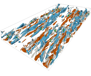
Figure 1. Schematic diagram of the rectangular channel of size $L_x \times L_y \times L_z=6{\rm \pi} h\times 2h \times 3{\rm \pi} h$ in the streamwise, wall-normal and spanwise directions, respectively, subjected to spanwise wall oscillations in the form of STW. The diagram also shows the instantaneous visualizations of the near-wall streaks of streamwise fluctuating velocity field $(u)$, marked with blue $(u<0)$ and red $(u>0)$ contours. The near-wall quasistreamwise vortical structures (QSVs) (identified using $\lambda _2=-0.02$) that are responsible for the generation of skin-friction are shown in grey colour, with their centres – identified using the eduction scheme of Jeong et al. (Reference Jeong, Hussain, Schoppa and Kim1997) – marked in green. The diagram also shows the waveform used for the actuation and the corresponding phase-averaged profiles of the spanwise velocity $\langle W \rangle$ for the $A0.50$ case. The phase-averaged profiles collapse well with the laminar solution (represented by dots) derived by Quadrio & Ricco (Reference Quadrio and Ricco2011).

Table 1. The details of the control parameters, the corresponding DR margins and the actual (local) friction Reynolds number for the controlled cases. The values of angular frequency $(\omega )$ and wavenumber $(\kappa )$ of STW were kept fixed at $0.16$ and $1.66$ in outer units based on the channel half-height $(h)$ and the centreline velocity $(U_c)$ of the plane Poiseuille flow, respectively.

The statistical quantities for the uncontrolled flow were obtained using 50 full three-dimensional (3-D) snapshots of velocity and pressure fields, covering a time window of 37 000 wall units, separated by 770 wall units. The statistical quantities for the controlled cases were obtained by employing the classical triple decomposition of Hussain & Reynolds (Reference Hussain and Reynolds1970), where an instantaneous quantity, for example, $U$ is decomposed into a time-invariant mean component $(\overline {U})$, a periodic fluctuating component $(\widetilde {U})$ and a purely stochastic component $(u)$. This decomposition can be expressed as $U=\overline {U}+\widetilde {U}+u=\langle U\rangle +u$, where $\langle {\cdot } \rangle$ represents the phase-averaged quantity. The phase-averaged quantities were obtained by averaging the corresponding instantaneous quantity over the phase $\xi =x-ct$ of the travelling wave, where $c=\omega /\kappa$ is the wave speed. The initial 20 cycles were discarded to elapse the initial transients, to ensure that the data collected to perform statistical calculations does not lie in the transient phases where the control drives the flow towards the drag reduced state. The data was collected for at least 40 cycles, corresponding to a time window of 12 000 wall units. This resulted in a computing time of approximately 90 000 core hours alone for the STW cases, distributed across 128 processors on the computational clusters of GRICAD, University of Grenoble-Alpes. We carefully compared the phase-averaged profile of the spanwise velocity $\langle W \rangle$ with the laminar solution of Quadrio & Ricco (Reference Quadrio and Ricco2011) for all the control cases listed in table 1, and found that we are in the GSL regime. For instance, it is seen at the top of figure 1 that the phase-averaged spanwise velocity profiles $\langle W \rangle$ (represented by lines) collapse well with the laminar solution of Quadrio & Ricco (Reference Quadrio and Ricco2011) (represented by dots) for the $A0.50$ case.

The simulations for the artificially forced cases (presented in § 4) were started from an initial turbulent flow field at $Re_\tau =180$, and the flow was left to develop for at least 3000 wall units before collecting the data to compute statistics to avoid biases in the statistical calculations related to the transient interval. Statistical data for these cases were obtained by averaging 25 full 3-D snapshots of instantaneous velocities and pressure fields, covering a time window of approximately 5000 wall units separated by approximately 200 wall units. Further details about the numerical schemes and the description of the code MULTIFAST used to perform the calculations are provided in Bauer, Tardu & Doche (Reference Bauer, Tardu and Doche2015) and Umair et al. (Reference Umair, Tardu and Doche2022).

Note that throughout the paper, we consistently used the local scaling parameters based on the actual $Re_\tau$ of the respective case, for reasons detailed in Umair et al. (Reference Umair, Tardu and Doche2022). Wherever necessary, a subscript ‘0’ was put on the quantities to highlight the use of reference scaling based on the $Re_\tau$ of the uncontrolled reference flow.

3. Turbulent enstrophy transport

3.1. Spanwise enstrophy transport

Figure 2 shows the response of turbulent enstrophy for all the cases listed in table 1. In canonical wall-bounded turbulent flows, the spanwise turbulent vorticity $\omega _z$ is dominant next to the wall. It is approximately equivalent to the uniform streamwise fluctuating stress $\tau ^\prime$ up to $y=3$, i.e. $\omega _z\approx -\partial u/\partial y$. In the large amplitude STW cases, $\omega _z$ is entirely annihilated up to $y=8$, with a negligible turbulent activity at the wall (i.e. $\tau ^\prime \approx 0$), and its peak is pushed towards the high buffer layer at $y=20$. This can be attributed to the strong damping of the near-wall streaks of streamwise fluctuating velocity. This is one of the outstanding effects of STW control compared with the HWO control – the profile of which collapses rather with the small amplitude STW case $A0.30$ (figure 2c). In the HWO case $\overline {\omega _z\omega _z}$ is damped in the viscous sublayer with a maximum at approximately $y=10$.

Figure 2. Mean profiles of turbulent enstrophy in each direction for uncontrolled and controlled cases: (a) streamwise $\overline {\omega _x\omega _x}$; (b) wall-normal $\overline {\omega _y\omega _y}$; and (c) spanwise $\overline {\omega _z\omega _z}$. Note that all the profiles are scaled with the local friction velocities of the drag reduced flows. Refer to table 1 for markers corresponding to different cases.

The production term for the mean spanwise turbulent enstrophy $\overline {\omega _z\omega _z}$ reads

(3.1)\begin{align} \overline{ P_{\omega_z\omega_z}} &= \underbrace{ \overline{2\widetilde{\varOmega_x}\left\langle \omega_z\frac{\partial w}{\partial x}\right\rangle} }_{\overline{ P^{1}_{\omega_z\omega_z} }}+ \underbrace{ \overline{2\widetilde{\varOmega_y}\left\langle \omega_z\frac{\partial w}{\partial y}\right\rangle} }_{\overline{ P^{2}_{\omega_z\omega_z} }}+ \underbrace{ \overline{2\widetilde{\varOmega_z}\left\langle \omega_z\frac{\partial w}{\partial z}\right\rangle} }_{\overline{ P^{3}_{\omega_z\omega_z} }}+ \underbrace{ 2\overline{\varOmega_z}\overline{\omega_z\frac{\partial w}{\partial z}} }_{\overline{ P^{4}_{\omega_z\omega_z} }}+ \underbrace{ 2\overline{\omega_x\omega_z\frac{\partial w}{\partial x}} }_{\overline{ P^{5}_{\omega_z\omega_z} }} \nonumber\\ &\quad +\underbrace{ 2\overline{\omega_y\omega_z\frac{\partial w}{\partial y}} }_{\overline{ P^{6}_{\omega_z\omega_z} }}+ \underbrace{ 2\overline{\omega_z\omega_z\frac{\partial w}{\partial z}} }_{\overline{ P^{7}_{\omega_z\omega_z} }}+ \underbrace{ 2\overline{\langle\omega_x\omega_z\rangle\frac{\partial\widetilde {W}}{\partial x}} }_{\overline{ P^{8}_{\omega_z\omega_z} }}+ \underbrace{ 2\overline{\langle\omega_y\omega_z\rangle\frac{\partial\widetilde {W}}{\partial y}} }_{\overline{ P^{9}_{\omega_z\omega_z} }}. \end{align}

The complete transport equation for each component can be found in Appendix A. The terms with ‘$\sim$’ are purely a consequence of the periodic forcing in the form of spanwise wall oscillations. In the canonical turbulent channel flows, the mean production term $\overline {P_{\omega _z\omega _z}}$ peaks at approximately $y=4$ within the viscous sublayer, and is roughly in equilibrium with the dissipation, as shown by the profiles in broken lines in figure 3(a). The viscous and turbulent diffusion terms are negligible except next to the wall at which they equilibrate mutually as expected. In the controlled cases, however, all the transport terms are shifted away from the viscous sublayer. In the HWO and low amplitude STW $(A<0.50)$ cases, the total mean production term peaks at approximately $y=9$, and it is even further shifted towards the middle of the buffer layer at $y\approx 20$ for the large amplitude STW cases (figure 3b). A similar attenuation and shift can also be observed in the dissipation $\overline {\epsilon _{\omega _z\omega _z}}$ (figure 4).

Figure 3. Budget of spanwise turbulent enstrophy transport for (a) HWO and (b$A1.25$ cases. The budget for the reference (uncontrolled) canonical case is also included in (a) in grey broken lines for comparison. The mean advection term $\overline {A_{\omega _z\omega _z}}$ is negligible, and hence not displayed in the figures to avoid cluttering.

Figure 4. Dissipation term $(\overline {\epsilon _{\omega _z\omega _z})}$ for the spanwise turbulent enstrophy. Refer to table 1 for markers corresponding to different cases.

In the canonical turbulent channel flows, the main contribution to the total production of $\omega _z$ comes from $\overline {P^{4}_{\omega _z\omega _z}}$ which emanates from the stretching of the spanwise vorticity interacting with the mean shear $\overline {\varOmega _z}$. It peaks at roughly $y=5$ in the viscous sublayer (figure 5c). For the large amplitude STW cases, it is almost annihilated up to $y=10$ and there is a shift in its peak of approximately 10 wall units. There is a difference in its maximum of approximately 20 % for the A1.25 case compared with the HWO case.

Figure 5. Production terms (a$\overline {P^{1}_{\omega _z\omega _z}}$, (b$\overline {P^{2}_{\omega _z\omega _z}}$, (c$\overline {P^{4}_{\omega _z\omega _z}}$, (d$\overline {P^{6}_{\omega _z\omega _z}}$, (e$\overline {P^{9}_{\omega _z\omega _z}}$ and (f$\overline {P^{1*}_{\omega _z\omega _z}}$. Refer to table 1 for markers corresponding to different cases.

The Stokes straining production terms $\overline {P^1_{\omega _z\omega _z}}$ and $\overline {P^2_{\omega _z\omega _z}}$ act to destroy the production of $\omega _z$ (figure 5a,b). The former originates from the twisting of $\widetilde {\varOmega _x}$ by the local $\partial w/\partial x$ gradient, while the latter due to the tilting of $\widetilde {\varOmega _y}$ by the local $\partial w/\partial y$ gradient. In the case of HWO, $\overline {P^1_{\omega _z\omega _z}}$ is almost negligible and $\overline {P^2_{\omega _z\omega _z}}$ is obviously absent (as $\partial \widetilde {W}/\partial x=0$), suggesting that both of these terms are a result of particular effects of STW.

There is another Stokes straining term, denoted by $\overline {P^9_{\omega _z\omega _z}}$, that is significant in both the HWO and STW cases. It results from the tilting of $\omega _y$ by the Stokes strain $\partial \widetilde {W}/\partial y$, and is large next to the edge of the viscous sublayer (figure 5e). The terms $\overline {P^{1}_{\omega _z\omega _z}}$ and $\overline {P^{9}_{\omega _z\omega _z}}$ can be combined to give

(3.2)\begin{equation} \overline{P^{1*}_{\omega_z\omega_z}} = \overline{P^{1}_{\omega_z\omega_z}} + \overline{P^{9}_{\omega_z\omega_z}} = 2\overline{\frac{\partial \widetilde {W}}{\partial y} \left\langle \omega_z\frac{\partial u}{\partial z} \right\rangle}. \end{equation}

The resulting term $\overline {P^{1*}_{\omega _z\omega _z}}$ now has a different physical meaning. As $\langle \omega _z {\partial u}/{\partial z}\rangle$ represents twisting of $\omega _x$ in its transport equation, $\overline {P^{1*}_{\omega _z\omega _z}}$ therefore represents the Stokes straining of $\langle \omega _z {\partial u}/{\partial z}\rangle$ by the deterministic streamwise vorticity $\widetilde {\varOmega _x}$. Figure 5(f) clearly shows that $\overline {P^{1*}_{\omega _z\omega _z}}$ is strongly attenuated in the STW cases of large amplitudes $(A>0.5)$, and its peak is further shifted away towards the buffer layer compared with HWO. The shift in $\overline {P^{1*}_{\omega _z\omega _z}}$ is as large as twice the thickness of the viscous sublayer for $A1.25$ case with respect to the HWO case.

A closer look at figure 6 reveals another peculiar behaviour of the $\overline {\omega _z\omega _z}$ production mechanism next to the wall. The production terms $\overline {P^{2}_{\omega _z\omega _z}}$ and $\overline {P^{6}_{\omega _z\omega _z}}$ cancel each other in the viscous sublayer and low buffer layer up to $y=10$. Figure 6(c) shows how well their phase averages coincide in a somewhat unexpected way at $y=2$. It is important to note that there is no direct link between $\overline {P^{2}_{\omega _z\omega _z}}$ and $\overline {P^{6}_{\omega _z\omega _z}}$. The former results from Stokes straining, while the latter comes from the local tilting term $\langle \omega _y{\partial w}/{\partial y} \rangle$. Next to the wall, $\overline {P^{6}_{\omega _z\omega _z}}$ reduces to the triple correlation $\overline {\omega _x\omega _y\omega _z}$, and can hardly be connected to $\overline {P^{2}_{\omega _z\omega _z}}$. The deterministic $\partial \langle W\rangle /\partial x$ reaches very large values at large imposed amplitudes next to the wall, and correlates almost perfectly with $\langle \omega _z\partial w/\partial y \rangle$ (figure 6d).

Figure 6. Phase wise variations of (a$\langle P^{2}_{\omega _z\omega _z} \rangle$, (b$\langle P^{6}_{\omega _z\omega _z} \rangle$ at different wall-normal locations, (c$\langle P^{2}_{\omega _z\omega _z} \rangle$ and $\langle P^{6}_{\omega _z\omega _z} \rangle$ and (d$\langle \partial W/\partial x\rangle$ and $\langle \omega _z\partial w/\partial y\rangle$ for $A0.95$ case at $y=2$, respectively. The values of $\langle \omega _z\partial w/\partial y\rangle$ are multiplied by a factor of 25.

To summarize, figure 6 recapitulates the major production terms of the $\overline {\omega _z\omega _z}$ transport equations, and figure 7 summarizes its main characteristics. There are finally two terms, namely, $\overline {P^{4}_{\omega _z\omega _z}}$ which is the major term in the uncontrolled flow and $\overline {P^{1*}_{\omega _z\omega _z}}$ which is specific to HWO and STW. All these production terms are the consequences of different mechanisms. Basically, the proper (direct) effect of STW is to reduce the intensity of the total production by Stokes straining, consequently its peak is shifted away from the wall to the buffer layer by approximately 10 wall units for large amplitude STW with respect to the HWO case.

Figure 7. Summary of main characteristics of the effect of control on the spanwise turbulent enstrophy production process.

3.2. Streamwise enstrophy transport

The production term for the streamwise turbulent enstrophy is given as

(3.3)\begin{align} \overline{ P_{\omega_x\omega_x}} &= \underbrace{ \overline{2\widetilde{\varOmega_x}\left\langle \omega_x\frac{\partial u}{\partial x}\right\rangle} }_{\overline{ P^{1}_{\omega_x\omega_x}}}+ \underbrace{ \overline{2\widetilde{\varOmega_y}\left\langle \omega_x\frac{\partial u}{\partial y}\right\rangle} }_{\overline{ P^{2}_{\omega_x\omega_x}}}+ \underbrace{ \overline{2\widetilde{\varOmega_z}\left\langle \omega_x\frac{\partial u}{\partial z}\right\rangle} }_{\overline{ P^{3}_{\omega_x\omega_x}}}- \underbrace{ 2\overline{\omega_x\frac{\partial w}{\partial x}}\frac{{\rm d}\overline {U}}{{\rm d}y} }_{\overline{ P^{4}_{\omega_x\omega_x}}} \nonumber\\ &\quad +\underbrace{ \overline{2\omega_x\omega_x\frac{\partial u}{\partial x}} }_{\overline{ P^{5}_{\omega_x\omega_x}}}+ \underbrace{ \overline{2\omega_x\omega_y\frac{\partial u}{\partial y}} }_{\overline{ P^{6}_{\omega_x\omega_x}}}+ \underbrace{ \overline{2\omega_x\omega_z\frac{\partial u}{\partial z}} }_{\overline{ P^{7}_{\omega_x\omega_x}}}+ \underbrace{ \overline{2\langle\omega_x\omega_x\rangle\frac{\partial\widetilde {U}}{\partial x}} }_{\overline{ P^{8}_{\omega_x\omega_x}}}+ \underbrace{ \overline{2\langle\omega_x\omega_y\rangle\frac{\partial\widetilde {U}}{\partial y}} }_{\overline{ P^{9}_{\omega_x\omega_x}}}. \end{align}

A careful analysis reveals that most of the terms in (3.3) are either negligible or cancel each other. Thus, the total production term $\overline {P_{\omega _x\omega _x}}$ effectively reduces to

(3.4)\begin{equation} \overline{P_{\omega_x\omega_x}} \approx \underbrace{2\overline{\widetilde{\varOmega_x} \left\langle \omega_x\frac{\partial u}{\partial x} \right\rangle}}_{\overline{P^1_{\omega_x\omega_x}}} \underbrace{- 2\overline{\omega_x\frac{\partial w}{\partial x}} \frac{{\rm d}\overline {U}}{{\rm d}y}}_{\overline{P^4_{\omega_x\omega_x}}}. \end{equation}

The production term $\overline {P^1_{\omega _x\omega _x}}$ represents the interaction of the Stokes shear $\partial \widetilde {W}/\partial y$ with the stretching of the streamwise vorticity $\langle \omega _x\partial u/\partial x \rangle$. This term is a direct consequence of forcing, and hence is absent in the canonical case. It increases with the amplitude of the STW, reaching large values for the $A1.25$ case, and peaks within the viscous sublayer at $y=5$ (figure 8a). Whereas in the case of HWO, it is negligible compared with the large amplitude STW cases.

Figure 8. Production terms (a$\overline {P^1_{\omega _x\omega _x}}$ and (b$\overline {P^4_{\omega _x\omega _x}}$. Refer to table 1 for markers corresponding to different cases.

The response of the streamwise turbulent enstrophy $\overline {\omega _x\omega _x}$ to the STW forcing is shown in figure 2(a). The local minimum and maximum in the profiles of $\overline {\omega _x\omega _x}$ are attributed to the streamwise vortices in the near-wall region (Kim, Moin & Moser Reference Kim, Moin and Moser1987). The local minimum increases with the amplitude of the STW, under the effect of Stokes shear $\partial \widetilde {W}/\partial y$ induced production $\overline {P^1_{\omega _x\omega _x}}$ which weakens the signature of the QSVs near the wall under large amplitude STW. Note that there is also a significant undermining of $\overline {\omega _x\omega _x}$ variation in the viscous sublayer for STW cases of $A>0.50$. For the $A1.25$ case, there is only a slight variation of $\overline {\omega _x\omega _x}$ between the local minimum and the wall, whereas in the case of uncontrolled flow there is an approximately $400\,\%$ increase at the same range of wall-normal distance. This is related to the lack of velocity-pressure gradient correlation in the spanwise velocity transport equation in the near-wall region (Umair et al. Reference Umair, Tardu and Doche2022).

For all the cases, the main production of $\overline {\omega _x\omega _x}$ comes from the tilting of $\omega _y$ by the mean shear ${\rm d}\overline {U}/{{\rm d}y}$ (figure 8b). This term, denoted by $\overline {P^4_{\omega _x\omega _x}}$ in (3.3), peaks roughly at $y=10\unicode{x2013}12.5$ for all the cases. Note that the profile of $\overline {P^4_{\omega _x\omega _x}}$ in HWO case collapse almost perfectly with the STW case $A0.30$. This strengthens again the observation made by Umair et al. (Reference Umair, Tardu and Doche2022) that the direct effects of STW mainly appear at $A>0.30$.

The turbulent transport (or turbulent diffusion) term in the uncontrolled flow is $\overline {T_{\omega _x\omega _x}}=-{\rm d}\overline {\omega _x\omega _xv}/{{\rm d}y}$, and is globally negligible compared with the other terms appearing in the transport equation of $\overline {\omega _x\omega _x}$. However, two additional transport terms emerge directly from the imposed unsteadiness in the STW cases. They are, respectively, given as $\overline {T^1_{\omega _x\omega _x}}=-2\overline {\langle \omega _x u\rangle \partial \widetilde {\varOmega _x}/\partial x}$ and $\overline {T^2_{\omega _x\omega _x}}=-2\overline {\langle \omega _x v\rangle \partial \widetilde {\varOmega _x}/\partial y}$ (Appendix A). Figure 9(b) shows that $\overline {T^2_{\omega _x\omega _x}}$ attains large values in the large amplitude STW cases. Recall that the turbulent transport terms correspond to the spatial redistribution of $\omega _x$. These nonlinear terms neither create nor destroy enstrophy, but act to simply redistribute it in space. A movie is attached showing that the production and transport are closely associated next to the wall at approximately $y=10$. The important point here is that the turbulent transport reaches large values comparable to the production (figure 10b). The direct consequence is the setup of excessive dissipation, which is almost twice the production near $y=10$. As mentioned before, the turbulent transport term is negligible for the uncontrolled case (represented by broken lines in figure 10a). In the HWO case, it is relatively smaller, and it is restricted to $y<10$ (figure 10a).

Figure 9. Turbulent transport (or turbulent diffusion) terms (a) $\overline {T^1_{\omega _x\omega _x}}$ and (b) $\overline {T^2_{\omega _x\omega _x}}$. Refer to table 1 for markers corresponding to different cases.

Figure 10. Budget of streamwise turbulent enstrophy transport for (a) HWO and (b$A1.25$ cases. The budget for the reference (uncontrolled) canonical case is also included in (a) in grey broken lines for comparison. The mean advection term $\overline {A_{\omega _x\omega _x}}$ is negligible, and hence not displayed in the figures to avoid cluttering.

To partially resume, $\overline {\omega _x\omega _x}$ attains large values close to the wall compared with the uncontrolled case. For large amplitude STW, the near-wall variation from the location of local minima and the wall is almost flattened as a consequence of the lack of a velocity-pressure gradient term in the transport equation of spanwise turbulent intensity $\overline {ww}$. The streamwise vorticity layers in the STW cases with large amplitudes are simultaneously produced and transported in space by the turbulent diffusion, but at the same time dissipate quickly and hence do not contribute actively to the formation of the near-wall QSVs.

3.3. Wall-normal enstrophy transport

The peculiar behaviour of the $\partial w/\partial x$ and $\partial u/\partial z$ shear layers, constituting $\omega _y$ at large amplitude STW, will be discussed in § 5.3 in detail. The maximum of $\overline {\omega _y\omega _y}$ is at $y\approx 10$ in the uncontrolled flow, and is shifted towards $y\approx 20$ in the large amplitude STW cases (figure 2b). Globally, all the transport terms in the transport equation of $\overline {\omega _y\omega _y}$ are weakened and shifted towards the middle of the buffer layer. This is clearly seen in the dissipation $(\overline {\epsilon _{\omega _y\omega _y}})$ profiles shown in figure 11(c). It shows also the suppression of $\omega _y$ activity in the viscous sublayer with $\overline {\epsilon _{\omega _y\omega _y}}\approx 0$ at the wall.

Figure 11. The main transport terms appearing in the transport equation of wall-normal turbulent enstrophy $\overline {\omega _y\omega _y}$: (a) the production term $\overline {P^4_{\omega _y\omega _y}}$; (b) the turbulent diffusion term $\overline {T^3_{\omega _y\omega _y}}$; and (c) the dissipation term $\overline {\epsilon _{\omega _y\omega _y}}$. Refer to table 1 for markers corresponding to different cases.

Most of the terms appearing in the production term of the wall-normal enstrophy (Appendix A) either vanish or are negligible. Among the first three terms involving the Stokes strain, the only term which differs from zero is $\overline {P^1_{\omega _y\omega _y}}$, but it is also found to be negligible (not shown). Hence, the major production of $\overline {\omega _y\omega _y}$ for the controlled cases still comes from the tilting of the wall-normal turbulent vorticity $\omega _y$ by the mean shear, i.e. the term $\overline {P^4_{\omega _y\omega _y}}$, as in the case of the uncontrolled flow. The maximum of the production term $\overline {P^4_{\omega _y\omega _y}}$ is shifted towards $y\approx 20$ in the large amplitude STW cases (figure 11a), which explains the shift in the maximum of $\overline {\omega _y\omega _y}$ in figure 2(b). The Stokes straining turbulent transport terms $\overline {T^1_{\omega _y\omega _y}}=-2\overline {\langle \omega _y u\rangle \partial \widetilde {\varOmega _y}/\partial x}$ and $\overline {T^2_{\omega _y\omega _y}}=-2\overline {\langle \omega _y v\rangle \partial \widetilde {\varOmega _y}/\partial y}$ are both nearly zero (not shown). The third turbulent transport term $\overline {T^3_{\omega _y\omega _y}}=-2\,{\rm d}\overline {\omega _y\omega _yv}/{{\rm d}y}$ has some importance at $y<20$ in the uncontrolled flow, but becomes insignificant in the STW cases (figure 11b).

4. Reynolds shear stress invariants and similarity with the suppression of the near-wall turbulent activity

Umair et al. (Reference Umair, Tardu and Doche2022) showed that both the streamwise and wall-normal turbulent intensities are strongly damped in the large amplitude STW cases, and that the response of the spanwise turbulent intensity is quite peculiar. In § 3 we highlighted the role of production terms appearing directly as a consequence of STW in the spanwise turbulent enstrophy transport in suppressing $\overline {\omega _z\omega _z}$ close to the wall when the imposed amplitude is large enough. Hence, the capital role of the large amplitude STW is to suppress the spanwise vorticity (and therefore streamwise velocity fluctuations) in the near-wall region. To assert this point, we conduct a few numerical experiments where the near-wall streamwise, wall-normal and spanwise velocity fluctuations, $u,v,w$, respectively, were explicitly damped up to a given wall-normal distance $\delta$. The main idea is to see which cases collapse to the large amplitude STW cases on the anisotropy invariant maps. The effect of suppressing the turbulent activity in the viscous sublayer on the near-wall turbulence regeneration mechanism and drag reduction has already been investigated by Lee & Kim (Reference Lee and Kim2002).

The generic algorithm used for the artificially forced cases is similar to Jiménez & Pinelli (Reference Jiménez and Pinelli1999), and can be written as

(4.1)\begin{equation} {} \zeta (y, t+{\rm d} t) = [\zeta (y, t) + {\rm d} t \, R(y)] F(y), \end{equation}

where $\zeta$ is either $u$, $v$ or $w$, $R$ is the appropriate right-hand side, and $F$ is the filter function given as

(4.2)\begin{equation} F(y) = 0.5 \{1 + \tanh [\alpha(y - \delta)] \}, \end{equation}

such that $F(y)\ll 1$ for $y\ll \delta$. Here, the parameter $\alpha$ controls the steepness of the filter function. For all the numerical experiments, the values of $\alpha$ and $\delta$ were kept fixed at 0.25 and 10, respectively, to suppress the fluctuations in the viscous sublayer and low buffer layer effectively up to $y\approx 8$. This was done deliberately to avoid strong damping of the fluctuations near the wall.

The initial response of the skin-friction coefficient and the resulting mean velocity profile are shown in figure 12. In agreement with Lee & Kim (Reference Lee and Kim2002), some moderate 30 % of drag reduction was achieved by suppressing $u$ up to $y\approx 8$, while suppressing $w$ up to the same wall-normal distance resulted in a significantly larger drag reduction margin of approximately 60 %. The near-wall mean velocity profile (figure 12b) agrees reasonably well with that of the typical drag reduction scenarios, exhibiting a linear behaviour in the viscous sublayer and an upward shift in the region beyond.

Figure 12. (a) Initial response of the skin friction coefficient $C_f$ (normalized by the skin-friction coefficient of the reference uncontrolled flow $C_{f0}$) and (b) mean velocity profiles for the uncontrolled reference case and the artificially forced cases, respectively.

Figure 13(a) shows response of the turbulent enstrophy profiles resulting from $u$ (or $\omega _z$) suppression in the low buffer layer. Near the wall, $\omega _z$ can be approximated as $\omega _z \approx - \partial u/\partial y$, and can be rewritten as $u \approx -y\omega _z(y=0)$. Therefore, suppressing $u$ is effectively similar to suppressing $\omega _z$ near the wall. This is indeed clear by looking at the profile of $\overline {\omega _z\omega _z}$ in figure 13(a), where $\overline {\omega _z\omega _z}$ is completely suppressed up to $y\approx 8$. A striking correspondence in the near-wall profile of $\overline {\omega _z\omega _z}$ can be seen with those of the STW controlled cases of $A\ge 0.75$ shown in figure 2(c), suggesting that the major effect of the STW is similar to the artificial suppression of the near-wall streaks up to the low buffer layer. Note that unlike STW control, artificial suppression of $u$ close to the wall also leads to the annihilation of $\overline {\omega _y\omega _y}$ up to $y\approx 8$, as in the case of canonical turbulent channel flows $\omega _y$ is dominated by $\partial u/\partial z$. In contrast, Umair et al. (Reference Umair, Tardu and Doche2022) have shown that in the large amplitude STW controlled cases, triangular wavy patterns of $\partial w/\partial x$ shear layers start to emerge. The contribution of $\partial w/\partial x$ to $\omega _y$ thus becomes increasingly significant, reaching approximately 10 times that of $\partial u/\partial z$ very close to the wall (not shown). This is one of the strong signatures of large amplitude STW that are essentially absent in both the HWO control and the canonical turbulent channel flows, and hence point towards strong structural alterations in the near-wall turbulence. These aspects will be discussed in more detail in the subsequent sections. Note that the removal of the spanwise vorticity in the viscous and low buffer layers do not modify the intensity and the peak location of the streamwise vorticity (figure 13a). However, the response of the $\overline {\omega _x\omega _x}$ intensity (figure 2a) under large amplitude STW is entirely different. The maximum of $\overline {\omega _x\omega _x}$ increases with the imposed amplitude, and there is curiously a negative drift of the streamwise vorticity layers. This is a consequence of the specific response of the near-wall turbulence to the large amplitude STW.

Figure 13. Mean profiles of turbulent enstrophy for (a) streamwise fluctuating field $(u)$, (b) wall-normal fluctuating field $(v)$ and (c) spanwise fluctuating field $(w)$ suppression case, respectively. Note that all the profiles are scaled with the local friction velocities of the forced cases. The dashed lines represent the profiles for the uncontrolled flow.

We now return to the next main point of our concern, namely the anisotropy invariants. The wall-bounded turbulent flows are characterized by the presence of organized motions, which reflects a high degree of turbulence anisotropy in the near-wall region. The anisotropy invariant map (AIM) introduced by Lumley & Newman (Reference Lumley and Newman1977) provides a convenient way to visualize the anisotropy of the turbulent velocity fluctuations through the Reynolds stress anisotropy tensor

(4.3)\begin{equation} a_{ij} = \frac{\overline{u_i u_j}}{\overline{u_iu_i}} - \frac{1}{3} \delta_{ij}, \end{equation}

where, $\overline {u_iu_i}$ is twice the turbulent kinetic energy, and $\delta _{ij}$ represents the Kronecker delta (Pope Reference Pope2000; Busse & Sandham Reference Busse and Sandham2012). A plot of the second and third scalar invariants of the tensor $a_{ij}$, defined as $II = a_{ij} a_{ji}$, and $III = a_{ij} a_{jk} a_{ki}$ (Frohnapfel et al. Reference Frohnapfel, Lammers, Jovanović and Durst2007), constitutes the well celebrated Lumley triangle or AIM within which all the realizable turbulent states must lie. The $II$ invariant characterizes the degree of anisotropy, while the $III$ invariant identifies its type. The left-hand and right-hand curve corresponds to the axisymmetric disc-like (straining) and axisymmetric rod-like (expansion) states, and are defined by $II = \pm 3/2 (4|III|/3)^{2/3}$. The two-component (2C) state is defined by the straight line $II = 2/9 + 2 III$. The three corners of the Lumley triangle or AIM correspond to three different limiting states. The left-hand corner corresponds to the isotropic two-component state, the corner on the right-hand side corresponds to the one-component (1C) axisymmetric state, while the bottom most corner of the triangle at $II=III=0$ corresponds to the isotropic turbulence state.

In the canonical turbulent channel flows, the trajectory of $II$ and $III$ invariants, shown in figure 14 with broken grey lines, lie close to the 2C state next to the wall, as $\overline {vv}$ is much weaker in comparison with $\overline {uu}$ and $\overline {ww}$. Away from the wall, in the viscous sublayer, the anisotropy increases reaching a maximum at $y\approx 8$ with $\overline {uu}$ larger than $\overline {vv}$ and $\overline {ww}$, pushing the trajectory towards the rod-like axisymmetric expansion state, in agreement with Moser, Kim & Mansour (Reference Moser, Kim and Mansour1999). Farther away from this region with increasing distance from the wall, the turbulence becomes more and more isotropic, ultimately acquiring the isotropic state at the centreline.

Figure 14. Invariant maps for (a,c,e) forced cases and (b,d,f) controlled cases.

Figure 14(a) shows the AIM for the case where $\omega _z$ (or $u$) is artificially suppressed. The AIMs of STW cases of large amplitudes $(A > 0.5)$ are surprisingly similar. Figure 14(f) shows, for instance, the AIM for $A0.75$ case. Similar results are obtained for $A0.95$ and $A1.25$ cases, hence not shown. The AIM trajectories are closely similar in both the large amplitude STW cases and $\omega _z$ (or $u$) suppressed case. In both cases, the trajectories are pushed rapidly from 2C state near the wall towards the disk-like axisymmetric contraction state in the buffer layer. This is mainly due to the annihilation of the near-wall streamwise turbulent intensity $(\overline {uu})$, which is the largest component in canonical turbulent channel flows. It is important to mention that this terminology is strictly related to the shape of the Reynolds stress tensor, which in no way should be confused with the shapes of the turbulent eddies. This point is clarified in detail by Simonsen & Krogstad (Reference Simonsen and Krogstad2005). The stress tensor has two equal positive and one negative eigenvalue in the disk-like axisymmetric state, which is opposite to the rod-like axisymmetric state. The AIM trajectory approaches the isotropic state transiting through the disk-like axisymmetry from a reduced anisotropy state and catches the trajectory of the canonical turbulent channel flow at $y > 30$.

Umair et al. (Reference Umair, Tardu and Doche2022) have shown that the structural modification brought to the wall turbulence by HWO and STW are similar up to $A<0.50$, and the effects specific to STW appear when the imposed amplitude is increased beyond $A>0.50$. The AIM analysis provides a nice additional proof, strengthening their arguments. Figure 14(b,d) shows the AIMs of STW case $A0.50$ and HWO, respectively. Both AIMs are quite similar, but differ from the $A0.75$ case. The trajectory changes rapidly from 2C state at the wall to the 2C axisymmetric state, but then stay relatively away from the isotropic state without touching the disk-like axisymmetric curve.

Frohnapfel et al. (Reference Frohnapfel, Lammers, Jovanović and Durst2007) considered the drag reduced flow from an anisotropy invariants point of view. Their analyses include the effects of additives, riblets, strong acceleration of boundary layers, and some forced boundary conditions. In their forced cases, they modify the boundary conditions to force near-wall turbulence to tend towards an axisymmetric state by imposing the spanwise fluctuating velocity to follow the wall-normal fluctuations. They obtain a DR of approximately 32 %, and conclude that the anisotropy of the turbulence increases towards the 1C limit in the near-wall region. Curiously, a closer look at their figure 9(b) reveals that their forcing also results in a significant suppression of the spanwise fluctuations. Artificial suppression of the wall-normal and spanwise fluctuating velocity field in the viscous and low buffer layers lead indeed to a scenario similar to their suggestion. This is clearly seen in figure 14(e) that shows the AIM when $w$ is suppressed up to $y\approx 8$, resulting in DR margin of approximately 60 % in agreement with Lee & Kim (Reference Lee and Kim2002). However, in the HWO and STW cases the trend in the AIM trajectory is entirely opposite, with a tendency towards isotropy, especially in STW of amplitude $A>0.50$. This shows that DR doesn't necessarily lead to increased anisotropy.

5. Effect on near-wall structures

5.1. Drifts of the near-wall QSVs

Quasistreamwise vortices are a prominent feature of the near-wall turbulent flow field. The QSVs have been recognized to play a significant role in the regeneration cycle of near-wall turbulence (Hamilton, Kim & Waleffe Reference Hamilton, Kim and Waleffe1995). They facilitate the exchange of momentum and energy in the near-wall region, and contribute significantly to the generation of Reynolds shear-stress by inducing ejection and sweep events.

Earlier studies have reported a drastic suppression of the near-wall quasistreamwise vortices due to the spanwise wall oscillations control. Yakeno, Hasegawa & Kasagi (Reference Yakeno, Hasegawa and Kasagi2014) studied the effect of homogeneous spanwise wall oscillations on the structural modifications of QSVs and report that the wall-normal location of the peak population density of QSVs is not affected by the presence of control. Extending their analysis to the STW control, Gallorini, Quadrio & Gatti (Reference Gallorini, Quadrio and Gatti2022) also report little to no shift in the position of QSVs. However, their analysis includes only one STW case that produces a DR margin of approximately 36 %. Umair et al. (Reference Umair, Tardu and Doche2022), on the other hand, point out that the QSVs reach their full maturity well above $y=20$ for the large amplitude STW. This point, indeed, needs to be clarified whether there is a shift in the position of the near-wall QSVs because of the imposed control.

To clarify this point, we examine the effect of STW actuation on the near-wall QSVs, focusing on detecting the drift $(\Delta d_s)$ in QSVs because of the control, if any. We employ the classical eduction scheme proposed by Jeong et al. (Reference Jeong, Hussain, Schoppa and Kim1997) to detect the near-wall QSVs. First, we detect the vortex cores where the value of $\lambda _2\le -0.02$ directly from the 3-D instantaneous velocity fields, where $\lambda _2$ being the second-largest eigenvalue of the symmetric and antisymmetric parts of the velocity gradient tensor. Then we identify and count only the structures that have streamwise extent greater than or equal to 150 wall units with inclination and titling angles in the range $-30^{\circ }$ to $+30^{\circ }$, respectively. The centre of each individual structure is obtained by locating the point where $\lambda _2$ attains its local minimum value within the structure. For all the cases studied here, we analysed an ensemble of at least 50 independent full 3-D instantaneous fields separated by roughly one full-through time unit $(20h/U_c)$. Since the criteria we chose to select the relevant QSVs is quite strict, as a consequence only few structures qualify to be considered as relevant candidates. For example, in the uncontrolled case, only approximately 90 structures met the imposed criteria in one snapshot of the instantaneous 3-D field. Figure 15 shows the $\lambda _2$ structures for a few of the cases studied here, and figure 16 shows their respective wall-normal distribution of the number of vortices, normalized by the maximum number of vortices.

Figure 15. Quasistreamwise vortical structures identified using $\lambda _2=-0.02$ along with the instantaneous field of streamwise velocity fluctuations $u$ (red, $u>0$; blue, $u<0$) on a wall-parallel plane at $y=15$ for (a) uncontrolled, (b) HWO, (c$A0.50$ and (d$A1.25$ case, respectively. The centres of the active QSVs educed using the criteria mentioned in § 5.1 are marked with yellow dots. The schematic diagram on the top shows the drift $(\Delta d_s)$ in the QSVs with respect to the canonical uncontrolled case. (HSS: high-speed streaks; LSS: low-speed streaks.)

Figure 16. The distribution of QSVs for the uncontrolled, HWO, $A0.50$ and $A1.25$ cases, respectively. The colours and markers in the plot correspond to those presented in figure 2.

For the canonical turbulent channel flow, the majority of the mature QSVs are located at $y\approx 24$, which is in agreement with Jeong et al. (Reference Jeong, Hussain, Schoppa and Kim1997). For the STW cases, however, we observe a systematic drift of QSVs away from the wall (figure 16). The drift is approximately six wall units for the $A0.50$ case, and 10 wall units for the $A1.25$ case. This is in disagreement with Gallorini et al. (Reference Gallorini, Quadrio and Gatti2022). These authors consider a single DR case with control parameters different from us. The closest case we have to them in terms of DR is $A0.30$ for which we observe a drift of approximately 4.5 wall units, while they report little to no drift. This discrepancy is plausibly coming from the criteria used to select the vortices. There are two points to consider: first, a ‘vortex’ has to be a ‘developed compact object’ of sufficient length to exist and be dynamically significant (mature). In the present work, we exclude vortices with streamwise extents shorter than 150 wall units in the same way as in Jeong et al. (Reference Jeong, Hussain, Schoppa and Kim1997), whereas Gallorini et al. (Reference Gallorini, Quadrio and Gatti2022) use rather a lower threshold length of 50 wall units, which means in their case a significant number of the detected vortices are immature low buffer layer structures. That indeed results in a twice smaller tilt angle of the structures they detect compared with Jeong et al. (Reference Jeong, Hussain, Schoppa and Kim1997). Second, in their controlled case they ‘opted to discard the same percentage of candidate vortices considered in the reference case, to avoid the assumption that control does not affect the length of QSV’, but forcing may affect the related probability density functions, and rejecting the same percentage as in the reference case may induce some bias. Whereas, in the present work, the criteria used to select the mature vortices is unique and consistent for all the cases. The capacity of near-wall QSVs to regenerate new structures is proportional to their intensity and inversely proportional to the square of their distances $(d_s)$ from the wall, as discussed in the following subsection. In the drag reduction scenarios, one would expect an increase in $d_s$, as observed in the present study. It may, however, happen that $d_s$ remains unaffected, but the intensity of the structures or their population density decreases.

In the subsection below, we estimate the drift directly from the instantaneous visualizations of the near-wall velocity streaks, and show that the drifts estimated from these two independent methods are in close agreement. Moreover, we show that the drift we observe combined with the rest of the results give us a reasonable estimate of the DR margin, thus increasing the quality of these results.

5.2. Near-wall streaks

The drift $\Delta d_s$ of the active streamwise $\omega _x$ vorticity layers decreases the drag according to the conceptual model of Jiménez (Reference Jiménez1994) and also discussed in some detail in Tardu (Reference Tardu1995). By active $\omega _x$ layers, we mean those layers from which the Reynolds shear stress producing QSVs emerge. Given the complexity of the wall response to the large amplitude STW discussed before, it is difficult to directly determine the drift. One somewhat qualitative, yet objective, way is to investigate the near-wall streaks in order to estimate the drift. The near-wall streaks in the canonical turbulent wall flows are the footprints of the QSVs, and are at best detected by the $\partial u/\partial z$ shear layers near the wall (Tardu Reference Tardu2022). The $\partial u/\partial z$ shear layers are the thin wall-normal turbulent vorticity $\omega _y$ layers separating the low- and high-speed streaks. Figure 17 shows a snapshot of $\partial u/\partial z$ in the uncontrolled, HWO and STW $A1.25$ case, respectively. The near-wall long streaks in the canonical flow are already detectable at the edge of the viscous sublayer with a streak spacing of approximately 80 wall units, in agreement with previously published results (Tardu Reference Tardu2014). The footprints of QSVs are weak at $y=5$ under HWO, and they are clearly discernible only at $y\approx 12$, with slightly larger spacing of approximately 100 wall units.

Figure 17. Instantaneous fields of $\partial u/\partial z$ shear layers at $y=5, 10, 12, 15\ \text {and}\ 20$ for the uncontrolled, HWO and $A1.25$ case, respectively. The blue colour represents the region where $\partial u/\partial z < 0$, while the red colour represents the region where $\partial u/\partial z > 0$. The contours are in the range $-0.2$ to $+0.2$.

On comparing figure 17(o,k), we see that in the case of large amplitude STW $(A1.25)$, we have to go even farther in the buffer layer, towards $y\approx 20$, to detect the near-wall streaks of reasonable coherence. Let us suppose that the drift $\Delta d_s$ in coherent $\partial u/\partial z$ layers can be related to the drift $\Delta d_s$ of the active streamwise vorticity layers from which Reynolds shear stress producing eddies emanate. Then figure 17 suggests that $\Delta d_s\approx 7$ in the HWO case, because the distribution of $\partial u/\partial z$ shear layers at $y\approx 12$ under HWO becomes comparable to that of the uncontrolled flow at $y=5$. Similarly, comparing figure 17(l,a) suggests that $\Delta d_s\approx 10$ for STW $A1.25$ case. These observations are in agreement with the previous discussion based on figure 16.

The flow is turbulent in all the controlled cases here, even though the laminar limit is closely approached for the $A1.25$ case. Thus, we have on purpose chosen to use the local wall units to scale the turbulent quantities, the main aim being here is to determine the proper structural modifications. All the quantities scaled by the local inner variables can easily be transformed to the quantities scaled with respect to those based on the friction velocity of the uncontrolled case. Figure 18(a) shows the wall-normal distribution of the streamwise turbulent enstrophy $\overline {\omega _x\omega _{x0}}$ and its main production term, $\overline {P^4_{\omega _x\omega _{x0}}}$ in figure 18(b), both scaled with the wall units based on the friction velocity of the uncontrolled flow. It is seen that $\overline {\omega _x\omega _{x0}}$ decreases systematically in the controlled cases, while the peak location $y_0$ is not significantly altered and is at approximately 20 wall units.

Figure 18. Wall-normal distribution of the (a) streamwise turbulent enstrophy $\overline {\omega _x\omega _{x0}}$, and (b) its main production term $\overline {P^4_{\omega _x\omega _{x0}}}$, scaled with the wall units based on the friction velocity of the uncontrolled flow. Refer to table 1 for markers corresponding to different cases.

Orlandi & Jiménez (Reference Orlandi and Jiménez1994) relates the location $d_s$ and intensity of the QSVs to the wall shear by

(5.1)\begin{equation} \tau^*_w \propto \left( \frac{\varGamma^*}{\nu d^{*2}_s} \right)^{1/2}, \end{equation}

in dimensional units. In this relation $\varGamma ^*={\rm \pi} R^{*2}\omega _x^*$ is the mean circulation of the QSVs, $d^*_s$ is the distance to the wall and $R$ is their radius. The qualifier ‘$*$’ here represents quantities in physical dimensional units. This approximate relationship is obtained through a physical argument based on the stagnation flow induced by the QSVs. It gives only a qualitative description of the effect of QSVs on the wall shear, but has the merit to relate intensity and the stand-off distance of the coherent eddies on $\tau _w$. According to (5.1), the rate of change of $\Delta \tau _{w0}$ can be related to

(5.2)\begin{equation} \frac{\Delta \tau_{w0}}{\tau_{w0}} = \frac{1}{2}\frac{\Delta \varGamma_0}{\varGamma_0} - \frac{\Delta d_{s0}}{d_{s0}}, \end{equation}

when adequately scaled with the wall units based on the friction velocity of the uncontrolled flow.

One of the observations emerging from figure 17 and the $\lambda _2$ structures, shown before in figure 15, is that the radius of the QSVs (scaled in local wall units), in a rough sense, remains unaffected in all the controlled cases. Using $R=$ constant and $\overline {\omega _x\omega _x}_0$ profiles (figure 18a), we estimated 42 % of DR for $A0.50$ case from (5.2), which is in close agreement with the value reported in table 1. However, (5.2) gives 80 % of drag reduction at the largest imposed amplitude $A1.25$ case, which is approximately 30 % overestimated. In any case, the $\Delta \varGamma _0/\varGamma _0$ term is found to contribute only 20 % to the DR. Consequently, the drift $\Delta d_{s0}/d_{s0}$ plays a critical role in the drag reduction mechanism investigated here.

Duggleby, Ball & Paul (Reference Duggleby, Ball and Paul2007) examined the effect of spanwise wall oscillations on the dynamics of the near-wall turbulent structures in a turbulent pipe flow using Karhunen–Loève decomposition. They argued that the main effect of the Stokes layer generated by spanwise wall oscillations is to push the structures away from the wall into the region of higher mean velocity by creating a zone where turbulent structures cannot form. As a consequence, the structures are advected faster with less time to interact with the roll modes to transfer energy, resulting in their shorter lifetime, and hence damping of the Reynolds shear stress generating bursting events. Our finding strengthens the arguments presented by them and is in full concordance with their interpretation that although drag reduction results in the decorrelation of the near-wall streaks and the QSVs, but it is the lifting of the turbulent structures away from the wall by the Stokes layer induced by the spanwise wall oscillations that results in drag reduction.

5.3. Shear layers of spanwise fluctuating velocity field

The spanwise fluctuating velocity field plays a prominent role in the near-wall turbulence. Even though they do not implicitly contribute to the production of turbulent kinetic energy, they are, however, linked to the Reynolds shear stress producing events, and hence intrinsically linked to the characteristics of the near-wall coherent structures (Tardu Reference Tardu2016). The connection between the spanwise fluctuating velocity field and the intense Reynolds shear stress generating events become clear if one considers the classical hairpin and horseshoe vortex paradigm. The spanwise fluctuating velocity field is nearly zero between the legs of the hairpin vortices, where the intense sweep or ejection events occur. As mentioned previously, the main production of the turbulent streamwise enstrophy comes from the tilting of the wall-normal vorticity by the mean shear, which reduces to $-2\overline {\omega _x({\partial w}/{\partial x})}({{\rm d}\overline {U}}/{{\rm d}y})$. Hence, the $\partial w/\partial x$ shear layers play a crucial role in the generation of $\omega _x$ prior to their roll up into QSVs (Brooke & Hanratty Reference Brooke and Hanratty1993; Tardu Reference Tardu2008Reference Tardu2014Reference Tardu2016). Hence, as we saw earlier, the suppression of the spanwise velocity fluctuations in the viscous sublayer results in significantly larger drag reduction compared with the suppression of the streamwise or wall-normal velocity fluctuations.

In the canonical turbulent channel flow, the $\partial w/\partial x$ shear layers are spotty and slightly stretched in the spanwise direction, as shown in figure 19(a). Using the multiscale approach, Tardu (Reference Tardu2022) showed that some of the $\partial w/\partial x$ shear layers may appear as spanwise streaks. As seen in figure 19(e), the tilting of these shear layers into identifiable elongated $\omega _x$ layers already set up at $y=10$. The morphology of $\partial w/\partial x$ shear layers under the large amplitude STW is strikingly different. The $\partial w/\partial x>0$ and $\partial w/\partial x<0$ are organized into $\varLambda$-shaped Christmas-tree-like structures resulting from a direct effect of STW (figure 19d). The titled $\omega _x$ layers are consequently also $\varLambda$-shaped, and they are being elongated into streamwise structures (figure 19h). It is necessary to go farther away from the wall towards $y\approx 30$ to identify the elongated streamwise vorticity layers (figure 20a,b). It is also roughly at this position that the contours of $\omega _x\partial w/\partial x$, related to the major production term $P^4_{\omega _x\omega _x}$, appear as long coherent streaky-like structures (figure 20c). The $\omega _x$ layers at $y=10$ for $A0.50$ case are organized more clearly into streamwise elongated structures compared with the $A1.25$ case. They achieve their conventional morphology at $y=20$, earlier than the $A1.25$ case.

Figure 19. Instantaneous field of $\partial w/\partial x$ shear layers and $\omega _x$ layers at $y=10$ for the uncontrolled, HWO, $A0.50$ and $A1.25$ case, respectively.

Figure 20. Instantaneous field of (a$\partial w/\partial x$ shear layers, (b$\omega _x$ layers and (c$\omega _x\partial w/\partial x$ layers at $y=30$ for $A1.25$ case.

The flow under STW control at large amplitudes develops its own structures in the low buffer layer. In the case of HWO, the $\partial w/\partial x$ shear layers are inclined in the streamwise direction, but do not exhibit $\varLambda$-shaped structures that are specific to the STW control. The origin of these structures is tricky to understand. The $\partial w/\partial x$ patterns next to the wall, in the large amplitude STW case, are too regular to be considered as induced by the random turbulence phenomenon. They are indeed related to the large $\partial \widetilde {W}/\partial x$ modulation occurring at the wall. Consider the instantaneous transport equation for the streamwise gradient of the instantaneous spanwise velocity field $(\partial W/\partial x)$ given as

(5.3)\begin{equation} \frac{{\rm D}}{{\rm D} t}\frac{\partial W}{\partial x} = \frac{\partial W}{\partial x} \frac{\partial V}{\partial y} - \frac{\partial V}{\partial x}\frac{\partial W}{\partial y} - \frac{\partial^2 P}{\partial x \partial z} + \nu\nabla^2\frac{\partial W}{\partial x}. \end{equation}

The complete analysis of $({{\rm D}}/{{\rm D} t})({\partial w}/{\partial x})({\partial w}/{\partial x})$, which contains 10 terms on the right-hand side (not shown), is complex, especially, because of the local pressure term appearing on the right-hand side of (5.3), and hence, is out of scope of the present investigation. After applying triple decomposition, several other terms appear on the right-hand side of (5.3), among which the term $({\partial \widetilde {W}}/{\partial x})({\partial v}/{\partial y})$, which represents the stretching of the Stokes shear $\partial \widetilde {W}/\partial x$ by the local $\partial v/\partial y$, is negligible at $y>5$, but reaches large values near the wall at $y\approx 0$. Figure 21(a,b) compares the $({\partial \widetilde {W}}/{\partial x})({\partial v}/{\partial y})$ contours with those of $\partial w/\partial x$ layers at $y=2.5$, respectively. A striking similarity emerges from these two figures. The Stokes shear $\partial \widetilde {W}/\partial x$ induces $\varLambda$-shaped $\partial w/\partial x$ next to the wall. The latter are further stretched, intensified and extended to the viscous sublayer. One quick way to estimate the quantitative importance of $({\partial \widetilde {W}}/{\partial x})({\partial v}/{\partial y})$ is to compare its r.m.s. value with the r.m.s. of $\partial w/\partial x$. A similar procedure has been conducted, for instance, by Brooke & Hanratty (Reference Brooke and Hanratty1993) in the local transport equation ${\rm D}\omega _x/{\rm D} t$. Figure 21(d) shows that the r.m.s. value of $({\partial \widetilde {W}}/{\partial x})({\partial v}/{\partial y})$ is as large as 30 % of the r.m.s. of $\partial w/\partial x$ at $y\approx 1$, and progressively disappears towards the edge of the viscous sublayer. Figure 21(c) shows the normalized cross-correlation coefficient $C$ between $({\partial \widetilde {W}}/{\partial x})({\partial v}/{\partial y})$ and $\partial w/\partial x$ at $y=2.5$. We observe specific cross-correlation patterns that are somewhat similar to the patterns observed in the autocorrelations of $({\partial \widetilde {W}}/{\partial x})({\partial v}/{\partial y})$ and $\partial w/\partial x$ (not shown). The cross-correlations reach values as large as 0.2, which is far from being negligible.

Figure 21. Instantaneous field of (a$({\partial \widetilde {W}}/{\partial x})({\partial v}/{\partial y})$ shear layers, (b$\partial w/\partial x$ layers, (c) their cross-correlation coefficient at $y=2.5$ and (d) the wall-normal distribution of the ratio of their root-mean-square (r.m.s.) values for $A1.25$ case.

From the visualizations presented in figure 15, it is clear that the classical topological features of the QSVs are only depicted at $y>20$ for large amplitude STW. Consequently, the peculiar $\varLambda$-shaped $\partial w/\partial x$ shear layers do not roll up into QSVs. Therefore, there is a drift of the active $\omega _x$ layers that lead to Reynolds shear-stress producing eddies at large amplitude STW.

6. Conclusions

In this study, we examined the effect of spanwise wall oscillations in the form of STW on the vorticity transport mechanism in a turbulent channel flow at Reynolds number $Re_\tau =180$. The frequency and wavelength of the imposed travelling wave were kept fixed, and only the amplitude was varied to examine the direct effect arising because of travelling-wave-like wall oscillations. At the largest amplitude studied here, the flow almost reached the relaminarization limit. Such a significant level of drag reduction cannot be achieved in case of HWO.

The wall-normal and spanwise turbulent enstrophy also show a significant reduction in their intensity, the latter almost vanishes in the viscous sublayer for large amplitudes STW. The contribution of the $\partial w/\partial x$ with respect to $\partial u/\partial z$ becomes increasingly important next to the wall for large amplitude STW. However, the attenuation of the wall-normal turbulent enstrophy is of subordinate importance compared with the spanwise turbulent enstrophy. This is also evident from the numerical experiments conducted in § 4, which demonstrates that suppressing the spanwise vorticity near the wall results also in a significant attenuation of $\omega _y$. The streamwise turbulent enstrophy shows a moderate increase in its intensity, and its near-wall variation is almost flattened as a consequence of a lack of a velocity-pressure gradient term in the transport equation of spanwise turbulent intensity, as explained in Umair et al. (Reference Umair, Tardu and Doche2022).

The main production term for the spanwise turbulent enstrophy is shifted in the middle of the buffer layer in large amplitude STW cases. The phasewise plots of the production terms, originating due to forcing, reveal that there is a destruction of the spanwise vorticity by the direct straining through $\partial \widetilde {W}/\partial x$, especially next to the wall. This particular effect is obviously absent in the case of HWO. Globally, STW of large amplitudes attenuates the production by Stokes straining effects and pushes the profiles towards the buffer layer.

For the streamwise turbulent enstrophy, the main production still originates from the tilting of the wall-normal vorticity by the mean shear, as in the case of uncontrolled flow. The location of the peak remains roughly at the same wall-normal location between $y=10\unicode{x2013}12.5$ for all the cases. Two additional turbulent diffusion terms emerge in the transport equation of the streamwise turbulent enstrophy that are directly related to the forcing. The second term attains large values comparable to the total production term in the large amplitude STW cases. However, these terms do not essentially create or destroy the enstrophy, but act to redistribute it in space. This is clearly evident in the movie attached as a supplementary material available at https://doi.org/10.1017/jfm.2023.478. Consequently, the level of dissipation gets enhanced to almost twice of the production at roughly $y=10$. Hence, the streamwise vorticity layers in the large amplitude STW cases are produced and transported in the space simultaneously, but also get dissipated quickly. As a consequence, these near-wall streamwise vorticity layers do not actively contribute in the regeneration mechanism of near-wall QSVs.

The artificial suppression of the near-wall streamwise fluctuating velocity field results in a significantly large drag reduction margin. A striking correspondence in the near-wall profile of the spanwise turbulent enstrophy can be seen with those of the STW controlled cases of large amplitudes, suggesting that the major effect of the STW is similar to the artificial suppression of the near-wall streaks up to the low buffer layer. This is clearly represented in the AIMs which show a striking resemblance to the large amplitude STW cases. In both cases, the trajectories are pushed rapidly from the 2C state near the wall towards the disk-like axisymmetric contraction state in the buffer layer.

The near-wall QSVs show a systematic drift away from the wall. It was calculated using two procedures: by identifying the location where QSVs are mostly populated, and also by looking at the instantaneous visualizations of the near-wall streaks. Both procedures give roughly the same drift. The observed drift combined with the rest of the results gives a reasonable estimate of the DR margin.

The spanwise fluctuating velocity field which plays a prominent role in the near-wall turbulence shows interesting features. The flow is nearly transitional at the largest imposed amplitude STW, wherein the buffer layer develops its own structures induced by the Stokes straining $\partial \widetilde {W}/\partial x$ and thus becomes entirely uncoupled with the rest of the flow. The $\partial w/\partial x$ shear layers, which are spotty and slightly stretched in the spanwise direction in the case of uncontrolled flow, begin to form coherent $\varLambda$-shaped patterns. However, these structures are too regular to be considered induced by the random turbulence phenomenon. The analysis of the instantaneous transport equation of $\partial W/\partial x$ shear layers show that these patterns are directly connected to the Stokes strain $\partial \widetilde {W}/\partial x$. These shear layers, however, do not play any active role in the generation of near-wall QSVs. Such a scenario is rarely observed in wall-bounded turbulence.

Supplementary movie

Supplementary movie is available at https://doi.org/10.1017/jfm.2023.478.

Acknowledgements

The simulations of the controlled cases were performed using the GRICAD infrastructure (https://gricad.univ-grenoble-alpes.fr), which is supported by Grenoble research communities. The simulations of the uncontrolled case were performed using the Froggy platform of the GRICAD infrastructure (https://gricad.univ-grenoble-alpes.fr), which is supported by the Région Auvergne-Rhóne-Alpes (GRANT CPER07_13 CIRA) and the Agence Nationale de la Recherche (Equip@Meso project reference no. ANR-10-EQPX-29-01 of the programme Investissements d'Avenir).

Funding

This research received no specific grant from any funding agency, commercial or not-for-profit sectors.

Declaration of interests

The authors report no conflict of interest.

Data availability statement

The data that support the findings of this study are available upon reasonable request from the corresponding author.

Appendix A. Transport equations of mean turbulent enstrophy field

The transport equation for the mean streamwise turbulent enstrophy $\overline {\omega _x\omega _x}$ is given as

(A1) \begin{equation} \left.\begin{aligned} \frac{\partial\overline{\omega_x\omega_x}}{\partial t} &= \overline{P_{\omega_x\omega_x}} + \overline{ A_{\omega_x\omega_x}} + \overline{ T_{\omega_x\omega_x}} + \overline{\epsilon_{\omega_x\omega_x}} + \overline{ D_{\omega_x\omega_x}},\\ &{\rm where}\\ \overline{ P_{\omega_x\omega_x}} &= \underbrace{ \overline{2\widetilde{\varOmega_x}\left\langle \omega_x\frac{\partial u}{\partial x}\right\rangle} }_{\overline{ P^{1}_{\omega_x\omega_x}}}+ \underbrace{ \overline{2\widetilde{\varOmega_y}\left\langle \omega_x\frac{\partial u}{\partial y}\right\rangle} }_{\overline{ P^{2}_{\omega_x\omega_x}}}+ \underbrace{ \overline{2\widetilde{\varOmega_z}\left\langle \omega_x\frac{\partial u}{\partial z}\right\rangle} }_{\overline{ P^{3}_{\omega_x\omega_x}}}- \underbrace{ 2\frac{{\rm d}\overline {U}}{{\rm d}y}\overline{\omega_x\frac{\partial w}{\partial x}} }_{\overline{ P^{4}_{\omega_x\omega_x}}}\\ &\quad +\underbrace{ \overline{2\omega_x\omega_x\frac{\partial u}{\partial x}} }_{\overline{ P^{5}_{\omega_x\omega_x}}}+ \underbrace{ \overline{2\omega_x\omega_y\frac{\partial u}{\partial y}} }_{\overline{ P^{6}_{\omega_x\omega_x}}}+ \underbrace{ \overline{2\omega_x\omega_z\frac{\partial u}{\partial z}} }_{\overline{ P^{7}_{\omega_x\omega_x}}}+ \underbrace{ \overline{2\langle\omega_x\omega_x\rangle\frac{\partial\widetilde {U}}{\partial x}} }_{\overline{ P^{8}_{\omega_x\omega_x}}}+ \underbrace{ \overline{2\langle\omega_x\omega_y\rangle\frac{\partial\widetilde {U}}{\partial y}} }_{\overline{ P^{9}_{\omega_x\omega_x}}},\\ \overline{ A_{\omega_x\omega_x}} &=-\underbrace{ \overline{\widetilde {U}\frac{\partial\langle\omega_x\omega_x\rangle}{\partial x}} }_{\overline{ A^{1}_{\omega_x\omega_x} }}- \underbrace{ \overline{\widetilde {V}\frac{\partial\langle\omega_x\omega_x\rangle}{\partial y}} }_{\overline{ A^{2}_{\omega_x\omega_x} }},\\ \overline{ T_{\omega_x\omega_x}} &=-\underbrace{ \overline{2\langle\omega_x u\rangle\frac{\partial\widetilde{\varOmega_x}}{\partial x}} }_{\overline{ T^{1}_{\omega_x\omega_x} }}- \underbrace{ \overline{2\langle\omega_x v\rangle\frac{\partial\widetilde{\varOmega_x}}{\partial y}} }_{\overline{ T^{2}_{\omega_x\omega_x} }}- \underbrace{ \frac{{\rm d}\overline{\omega_x\omega_x v}}{{\rm d}y} }_{\overline{ T^{3}_{\omega_x\omega_x} }},\\ \overline{\epsilon_{\omega_x\omega_x}} &=-2\left(\overline{\frac{\partial\omega_x}{\partial x}\frac{\partial\omega_x}{\partial x}} + \overline{\frac{\partial\omega_x}{\partial y}\frac{\partial\omega_x}{\partial y}} + \overline{\frac{\partial\omega_x}{\partial z}\frac{\partial\omega_x}{\partial z}}\right) \text{and}\\ \overline{ D_{\omega_x\omega_x}} &= \frac{d^2\overline{\omega_x\omega_x}}{{{\rm d}y}^2}. \end{aligned}\right\} \end{equation}

The transport equation for the mean wall-normal turbulent enstrophy $\overline {\omega _y\omega _y}$ is given as

(A2) \begin{equation} \left.\begin{aligned} \frac{\partial\overline{\omega_y\omega_y}}{\partial t} &= \overline{ P_{\omega_y\omega_y}} + \overline{ A_{\omega_y\omega_y}} + \overline{ T_{\omega_y\omega_y}} + \overline{\epsilon_{\omega_y\omega_y}} + \overline{ D_{\omega_y\omega_y}}=0,\\ &{\rm where}\\ \overline{ P_{\omega_y\omega_y}} &= \underbrace{ \overline{2\widetilde{\varOmega_x}\left\langle \omega_y\frac{\partial v}{\partial x}\right\rangle} }_{\overline{ P^{1}_{\omega_y\omega_y} }}+ \underbrace{ \overline{2\widetilde{\varOmega_y}\left\langle \omega_y\frac{\partial v}{\partial y}\right\rangle} }_{\overline{ P^{2}_{\omega_y\omega_y} }}+ \underbrace{ \overline{2\widetilde{\varOmega_z}\left\langle \omega_y\frac{\partial v}{\partial z}\right\rangle} }_{\overline{ P^{3}_{\omega_y\omega_y} }}+ \underbrace{ 2\overline{\varOmega_z}\overline{\omega_y\frac{\partial v}{\partial z}} }_{\overline{ P^{4}_{\omega_y\omega_y} }}\\ &\quad +\underbrace{ \overline{2\omega_x\omega_y\frac{\partial v}{\partial x}} }_{\overline{ P^{5}_{\omega_y\omega_y} }}+ \underbrace{ \overline{2\omega_y\omega_y\frac{\partial v}{\partial y}} }_{\overline{ P^{6}_{\omega_y\omega_y} }}+ \underbrace{ \overline{2\omega_z\omega_y\frac{\partial v}{\partial z}} }_{\overline{ P^{7}_{\omega_y\omega_y} }}\\ &\quad +\underbrace{ \overline{2\langle\omega_x\omega_y\rangle\frac{\partial\widetilde {V}}{\partial x}} }_{\overline{ P^{8}_{\omega_y\omega_y} }}+ \underbrace{ \overline{2\langle\omega_y\omega_y\rangle\frac{\partial\widetilde {V}}{\partial y}} }_{\overline{ P^{9}_{\omega_y\omega_y} }},\\ \overline{A_{\omega_y\omega_y} } &=-\underbrace{ \overline{\widetilde {U}\frac{\partial\langle\omega_y\omega_y\rangle}{\partial x}} }_{\overline{ A^{1}_{\omega_y\omega_y} }}- \underbrace{ \overline{\widetilde {V}\frac{\partial\langle\omega_y\omega_y\rangle}{\partial y}} }_{\overline{ A^{2}_{\omega_y\omega_y} }},\\ \overline{ T_{\omega_y\omega_y}} &= \underbrace{ -\overline{2\langle\omega_y u\rangle\frac{\partial\widetilde{\varOmega_y}}{\partial x}} }_{\overline{ T^{1}_{\omega_y\omega_y} }}- \underbrace{ \overline{2\langle\omega_y v\rangle\frac{\partial\widetilde{\varOmega_y}}{\partial y}} }_{\overline{ T^{2}_{\omega_y\omega_y} }}- \underbrace{ \frac{{\rm d}\overline{\omega_y\omega_y v}}{{\rm d}y} }_{\overline{ T^{3}_{\omega_y\omega_y} }},\\ \overline{\epsilon_{\omega_y\omega_y}} &=-2\left(\overline{\frac{\partial\omega_y}{\partial x}\frac{\partial\omega_y}{\partial x}} + \overline{\frac{\partial\omega_y}{\partial y}\frac{\partial\omega_y}{\partial y}} + \overline{\frac{\partial\omega_y}{\partial z}\frac{\partial\omega_y}{\partial z}}\right) \text{and}\\ \overline{ D_{\omega_y\omega_y}} &= \frac{d^2\overline{\omega_y\omega_y}}{{{\rm d}y}^2}. \end{aligned}\right\} \end{equation}

Finally, the transport equation for the mean spanwise turbulent enstrophy $\overline {\omega _z\omega _z}$ is given as

(A3) \begin{equation} \left.\begin{aligned} \frac{\partial\overline{\omega_z\omega_z}}{\partial t} &= \overline{ P_{\omega_z\omega_z}} + \overline{ A_{\omega_z\omega_z}} + \overline{ T_{\omega_z\omega_z}} + \overline{\epsilon_{\omega_z\omega_z}} + \overline{ D_{\omega_z\omega_z}}=0,\\ &{\rm where}\\ \overline{ P_{\omega_z\omega_z}} &= \underbrace{ \overline{2\widetilde{\varOmega_x}\left\langle \omega_z\frac{\partial w}{\partial x}\right\rangle} }_{\overline{ P^{1}_{\omega_z\omega_z} }}+ \underbrace{ \overline{2\widetilde{\varOmega_y}\left\langle \omega_z\frac{\partial w}{\partial y}\right\rangle} }_{\overline{ P^{2}_{\omega_z\omega_z} }}+ \underbrace{ \overline{2\widetilde{\varOmega_z}\left\langle \omega_z\frac{\partial w}{\partial z}\right\rangle} }_{\overline{ P^{3}_{\omega_z\omega_z} }}+ \underbrace{ 2\overline{\varOmega_z}\overline{\omega_z\frac{\partial w}{\partial z}} }_{\overline{ P^{4}_{\omega_z\omega_z} }}\\ &\quad +\underbrace{ 2\overline{\omega_x\omega_z\frac{\partial w}{\partial x}} }_{\overline{ P^{5}_{\omega_z\omega_z} }}+ \underbrace{ 2\overline{\omega_y\omega_z\frac{\partial w}{\partial y}} }_{\overline{ P^{6}_{\omega_z\omega_z} }}+ \underbrace{ 2\overline{\omega_z\omega_z\frac{\partial w}{\partial z}} }_{\overline{ P^{7}_{\omega_z\omega_z} }}\\ &\quad +\underbrace{ 2\overline{\langle\omega_x\omega_z\rangle\frac{\partial\widetilde {W}}{\partial x}} }_{\overline{ P^{8}_{\omega_z\omega_z} }}+ \underbrace{ 2\overline{\langle\omega_y\omega_z\rangle\frac{\partial\widetilde {W}}{\partial y}} }_{\overline{ P^{9}_{\omega_z\omega_z} }},\\ \overline{ A_{\omega_z\omega_z}} &=-\underbrace{ \overline{\widetilde {U}\frac{\partial\langle\omega_z\omega_z\rangle}{\partial x}} }_{\overline{ A^{1}_{\omega_z\omega_z} }}- \underbrace{ \overline{\widetilde {V}\frac{\partial\langle\omega_z\omega_z\rangle}{\partial y}} }_{\overline{ A^{2}_{\omega_z\omega_z} }},\\ \overline{ T_{\omega_z\omega_z}} &= \underbrace{ -2\overline{\langle\omega_z u\rangle\frac{\partial\widetilde{\varOmega_z}}{\partial x}} }_{\overline{ T^{1}_{\omega_z\omega_z} }}- \underbrace{ 2\overline{\langle\omega_z v\rangle\frac{\partial\widetilde{\varOmega_z}}{\partial y}} }_{\overline{ T^{2}_{\omega_z\omega_z} }}- \underbrace{ 2\overline{\omega_z v}\frac{{\rm d}\overline{\varOmega_z}}{{\rm d}y} }_{\overline{ T^{3}_{\omega_z\omega_z} }}- \underbrace{ \frac{{\rm d}\overline{\omega_z\omega_z v}}{{\rm d}y} }_{\overline{ T^{4}_{\omega_z\omega_z} }},\\ \overline{\epsilon_{\omega_z\omega_z}} &=-2\left(\overline{\frac{\partial\omega_z}{\partial x}\frac{\partial\omega_z}{\partial x}} + \overline{\frac{\partial\omega_z}{\partial y}\frac{\partial\omega_z}{\partial y}} + \overline{\frac{\partial\omega_z}{\partial z}\frac{\partial\omega_z}{\partial z}}\right) \text{and}\\ \overline{ D_{\omega_z\omega_z}} &= \frac{{\rm d}^2\overline{\omega_z\omega_z}}{{{\rm d}y}^2}. \end{aligned}\right\} \end{equation}

References

Agostini, L., Touber, E. & Leschziner, M.A. 2014 Spanwise oscillatory wall motion in channel flow: drag-reduction mechanisms inferred from DNS-predicted phase-wise property variations at $Re_\tau =1000$. J. Fluid Mech. 743, 606635.CrossRefGoogle Scholar
Agostini, L., Touber, E. & Leschziner, M.A. 2015 The turbulence vorticity as a window to the physics of friction-drag reduction by oscillatory wall motion. Intl J. Heat Fluid Flow 51, 315.CrossRefGoogle Scholar
Akhavan, R., Jung, W.J. & Mangiavacchi, N. 1993 Turbulence control in wall-bounded flows by spanwise ocillations. Appl. Sci. Res. 51, 299303.CrossRefGoogle Scholar
Auteri, F., Baron, A., Belan, M., Campanardi, G. & Quadrio, M. 2010 Experimental assessment of turbulent drag reduction by traveling waves in a turbulent pipe flow. Phys. Fluids 22, 115103.CrossRefGoogle Scholar
Bauer, F., Tardu, S. & Doche, O. 2015 Efficiency of high accuracy DRP schemes in direct numerical simulations of incompressible turbulent flows. Comput. Fluids 107, 123140.CrossRefGoogle Scholar
Brooke, J.W. & Hanratty, T.J. 1993 Origin of turbulence–producing eddies in a channel flow. Phys. Fluids A 5, 10111022.CrossRefGoogle Scholar
Busse, A. & Sandham, N.D. 2012 Parametric forcing approach to rough-wall turbulent channel flow. J. Fluid Mech. 712, 169202.CrossRefGoogle Scholar
Choi, K.-S., DeBisschop, J.-R. & Clayton, B.R. 1998 Turbulent boundary-layer control by means of spanwise-wall oscillation. AIAA J. 36 (7), 11571163.CrossRefGoogle Scholar
Dhanak, M.R. & Si, C. 1999 On reduction of turbulent wall friction through spanwise wall oscillations. J. Fluid Mech. 383, 175195.CrossRefGoogle Scholar
Duggleby, A., Ball, K.S. & Paul, M.R. 2007 The effect of spanwise wall oscillation on turbulent pipe flow structures resulting in drag reduction. Phys. Fluids 19 (12), 125107.CrossRefGoogle Scholar
Frohnapfel, B., Lammers, P., Jovanović, J. & Durst, F. 2007 Interpretation of the mechanism associated with turbulent drag reduction in terms of anisotropy invariants. J. Fluid Mech. 577, 457466.CrossRefGoogle Scholar
Gallorini, E., Quadrio, M. & Gatti, D. 2022 Coherent near-wall structures and drag reduction by spanwise forcing. Phys. Rev. Fluids 7, 114602.CrossRefGoogle Scholar
Gatti, D. & Quadrio, M. 2013 Performance losses of drag-reducing spanwise forcing at moderate values of the Reynolds number. Phys. Fluids 25, 125109.CrossRefGoogle Scholar
Gatti, D. & Quadrio, M. 2016 Reynolds-number dependence of turbulent skin-friction drag reduction induced by spanwise forcing. J. Fluid Mech. 802, 553582.CrossRefGoogle Scholar
Ge, M. & Jin, G. 2017 Response of turbulent enstrophy to sudden implementation of spanwise wall oscillation in channel flow. Appl. Math. Mech. 38, 11591170.CrossRefGoogle Scholar
Hamilton, J.M., Kim, J. & Waleffe, F. 1995 Regeneration mechanisms of near-wall turbulence structures. J. Fluid Mech. 287, 317348.CrossRefGoogle Scholar
Hurst, E., Yang, Q. & Chung, Y.M. 2014 The effect of Reynolds number on turbulent drag reduction by streamwise travelling waves. J. Fluid Mech. 759, 2855.CrossRefGoogle Scholar
Hussain, A.K.M.F. & Reynolds, W.C. 1970 The mechanics of an organized wave in turbulent shear flow. J. Fluid Mech. 41, 241258.CrossRefGoogle Scholar
Jeong, J., Hussain, F., Schoppa, W. & Kim, J. 1997 Coherent structures near the wall in a turbulent channel flow. J. Fluid Mech. 332, 185214.CrossRefGoogle Scholar
Jiménez, J. 1994 On the structure and control of near wall turbulence. Phys. Fluids 6 (2), 944953.CrossRefGoogle Scholar
Jiménez, J. & Pinelli, A. 1999 The autonomous cycle of near-wall turbulence. J. Fluid Mech. 389, 335359.CrossRefGoogle Scholar
Jung, W.J., Mangiavacchi, N. & Akhavan, R. 1992 Suppression of turbulence in wall-bounded flows by high-frequency spanwise wall oscillations. Phys. Fluids A 4 (8), 16051607.CrossRefGoogle Scholar
Kempaiah, K.U., Scarano, F., Elsinga, G.E., van Oudheusden, B.W. & Bermel, L. 2020 3-dimensional particle image velocimetry based evaluation of turbulent skin-friction reduction by spanwise wall oscillation. Phys. Fluids 32 (8), 085111.CrossRefGoogle Scholar
Kim, J., Moin, P. & Moser, R. 1987 Turbulence statistics in fully developed channel flow at low Reynolds number. J. Fluid Mech. 177, 133166.CrossRefGoogle Scholar
Laadhari, F., Skandaji, L. & Morel, R. 1994 Turbulence reduction in a boundary layer by a local spanwise oscillating surface. Phys. Fluids 6 (10).CrossRefGoogle Scholar
Lee, C. & Kim, J. 2002 Control of the viscous sublayer for drag reduction. Phys. Fluids 14 (7), 25232529.CrossRefGoogle Scholar
Lumley, J.L. & Newman, G.R. 1977 The return to isotropy of homogeneous turbulence. J. Fluid Mech. 82 (1), 161178.CrossRefGoogle Scholar
Marusic, I., Chandaran, D., Rouhi, A., Fu, M.K., Wine, D., Holloway, B., Chung, D. & Smits, A.J. 2021 An energy-efficient pathway to turbulent drag reduction. Nat. Commun. 12, 5805.CrossRefGoogle ScholarPubMed
Moser, R.D., Kim, J. & Mansour, N.N. 1999 Direct numerical simulation of turbulent channel flow up to $Re_\tau =590$. Phys. Fluids 11, 943945.CrossRefGoogle Scholar
Orlandi, P. & Jiménez, J. 1994 On the generation of turbulent wall friction. Phys. Fluids 6 (2), 634641.CrossRefGoogle Scholar
Pope, S.B. 2000 Turbulent Flows. Cambridge University Press.CrossRefGoogle Scholar
Quadrio, M. & Ricco, P. 2003 Initial response of a turbulent channel flow to spanwise oscillation of the walls. J. Turbul. 4, N7.CrossRefGoogle Scholar
Quadrio, M. & Ricco, P. 2011 The laminar generalized Stokes layer and turbulent drag reduction. J. Fluid Mech. 667, 135157.CrossRefGoogle Scholar
Quadrio, M., Ricco, P. & Viotti, C. 2009 Streamwise-travelling waves of spanwise wall velocity for turbulent drag reduction. J. Fluid Mech. 627, 161178.CrossRefGoogle Scholar
Ricco, P. 2004 Modification of near-wall turbulence due to spanwise oscillations. J. Turbul. 5, N24.CrossRefGoogle Scholar
Ricco, P., Ottonelli, C., Hasegawa, Y. & Quadrio, M. 2012 Changes in turbulent dissipation in a channel flow with oscillating walls. J. Fluid Mech. 700, 77104.CrossRefGoogle Scholar
Ricco, P., Skotes, M. & Leschziner, M.A. 2021 A review of turbulent skin-friction drag reduction by near-wall transverse forcing. Prog. Aerosp. Sci. 123, 100713.CrossRefGoogle Scholar
Simonsen, A.J. & Krogstad, P.-Å. 2005 Turbulent stress invariant analysis: clarification of existing terminology. Phys. Fluids 17 (8), 088103.CrossRefGoogle Scholar
Tardu, S.F. 1995 Coherent structures and riblets. Appl. Sci. Res. 54, 349385.CrossRefGoogle Scholar
Tardu, S.F. 2008 Stochastic synchronization of the near wall turbulence. Phys. Fluids 20, 045105.Google Scholar
Tardu, S. 2014 Transport and Coherent Structures in Wall Turbulence. Wiley-ISTE.CrossRefGoogle Scholar
Tardu, S. 2016 Concomitance of the local spanwise velocity and production in wall turbulence. Phys. Fluids 28 (1).CrossRefGoogle Scholar
Tardu, S. 2022 Multiscale analysis of some shear layers in a fully developed turbulent channel flow. Comput. Fluids 240, 105459.CrossRefGoogle Scholar
Touber, E. & Leschziner, M.A. 2012 Near-wall streak modification by spanwise oscillatory wall motion and drag-reduction mechanisms. J. Fluid Mech. 693, 150200.CrossRefGoogle Scholar
Trujillo, S.M., Bogard, D.G. & Ball, K.S. 1997 Turbulent boundary layer drag reduction using an oscillating wall. In AIAA, pp. 97–1870.Google Scholar
Umair, M., Tardu, S. & Doche, O. 2022 Reynolds stresses transport in a turbulent channel flow subjected to streamwise traveling waves. Phys. Rev. Fluids 7, 054601.CrossRefGoogle Scholar
Yakeno, A., Hasegawa, Y. & Kasagi, N. 2014 Modification of quasi-streamwise vortical structure in a drag-reduced turbulent channel flow with spanwise wall oscillation. Phys. Fluids 26, 085109.CrossRefGoogle Scholar
Figure 0

Figure 1. Schematic diagram of the rectangular channel of size $L_x \times L_y \times L_z=6{\rm \pi} h\times 2h \times 3{\rm \pi} h$ in the streamwise, wall-normal and spanwise directions, respectively, subjected to spanwise wall oscillations in the form of STW. The diagram also shows the instantaneous visualizations of the near-wall streaks of streamwise fluctuating velocity field $(u)$, marked with blue $(u<0)$ and red $(u>0)$ contours. The near-wall quasistreamwise vortical structures (QSVs) (identified using $\lambda _2=-0.02$) that are responsible for the generation of skin-friction are shown in grey colour, with their centres – identified using the eduction scheme of Jeong et al. (1997) – marked in green. The diagram also shows the waveform used for the actuation and the corresponding phase-averaged profiles of the spanwise velocity $\langle W \rangle$ for the $A0.50$ case. The phase-averaged profiles collapse well with the laminar solution (represented by dots) derived by Quadrio & Ricco (2011).

Figure 1

Table 1. The details of the control parameters, the corresponding DR margins and the actual (local) friction Reynolds number for the controlled cases. The values of angular frequency $(\omega )$ and wavenumber $(\kappa )$ of STW were kept fixed at $0.16$ and $1.66$ in outer units based on the channel half-height $(h)$ and the centreline velocity $(U_c)$ of the plane Poiseuille flow, respectively.

Figure 2

Figure 2. Mean profiles of turbulent enstrophy in each direction for uncontrolled and controlled cases: (a) streamwise $\overline {\omega _x\omega _x}$; (b) wall-normal $\overline {\omega _y\omega _y}$; and (c) spanwise $\overline {\omega _z\omega _z}$. Note that all the profiles are scaled with the local friction velocities of the drag reduced flows. Refer to table 1 for markers corresponding to different cases.

Figure 3

Figure 3. Budget of spanwise turbulent enstrophy transport for (a) HWO and (b$A1.25$ cases. The budget for the reference (uncontrolled) canonical case is also included in (a) in grey broken lines for comparison. The mean advection term $\overline {A_{\omega _z\omega _z}}$ is negligible, and hence not displayed in the figures to avoid cluttering.

Figure 4

Figure 4. Dissipation term $(\overline {\epsilon _{\omega _z\omega _z})}$ for the spanwise turbulent enstrophy. Refer to table 1 for markers corresponding to different cases.

Figure 5

Figure 5. Production terms (a$\overline {P^{1}_{\omega _z\omega _z}}$, (b$\overline {P^{2}_{\omega _z\omega _z}}$, (c$\overline {P^{4}_{\omega _z\omega _z}}$, (d$\overline {P^{6}_{\omega _z\omega _z}}$, (e$\overline {P^{9}_{\omega _z\omega _z}}$ and (f$\overline {P^{1*}_{\omega _z\omega _z}}$. Refer to table 1 for markers corresponding to different cases.

Figure 6

Figure 6. Phase wise variations of (a$\langle P^{2}_{\omega _z\omega _z} \rangle$, (b$\langle P^{6}_{\omega _z\omega _z} \rangle$ at different wall-normal locations, (c$\langle P^{2}_{\omega _z\omega _z} \rangle$ and $\langle P^{6}_{\omega _z\omega _z} \rangle$ and (d$\langle \partial W/\partial x\rangle$ and $\langle \omega _z\partial w/\partial y\rangle$ for $A0.95$ case at $y=2$, respectively. The values of $\langle \omega _z\partial w/\partial y\rangle$ are multiplied by a factor of 25.

Figure 7

Figure 7. Summary of main characteristics of the effect of control on the spanwise turbulent enstrophy production process.

Figure 8

Figure 8. Production terms (a$\overline {P^1_{\omega _x\omega _x}}$ and (b$\overline {P^4_{\omega _x\omega _x}}$. Refer to table 1 for markers corresponding to different cases.

Figure 9

Figure 9. Turbulent transport (or turbulent diffusion) terms (a) $\overline {T^1_{\omega _x\omega _x}}$ and (b) $\overline {T^2_{\omega _x\omega _x}}$. Refer to table 1 for markers corresponding to different cases.

Figure 10

Figure 10. Budget of streamwise turbulent enstrophy transport for (a) HWO and (b$A1.25$ cases. The budget for the reference (uncontrolled) canonical case is also included in (a) in grey broken lines for comparison. The mean advection term $\overline {A_{\omega _x\omega _x}}$ is negligible, and hence not displayed in the figures to avoid cluttering.

Figure 11

Figure 11. The main transport terms appearing in the transport equation of wall-normal turbulent enstrophy $\overline {\omega _y\omega _y}$: (a) the production term $\overline {P^4_{\omega _y\omega _y}}$; (b) the turbulent diffusion term $\overline {T^3_{\omega _y\omega _y}}$; and (c) the dissipation term $\overline {\epsilon _{\omega _y\omega _y}}$. Refer to table 1 for markers corresponding to different cases.

Figure 12

Figure 12. (a) Initial response of the skin friction coefficient $C_f$ (normalized by the skin-friction coefficient of the reference uncontrolled flow $C_{f0}$) and (b) mean velocity profiles for the uncontrolled reference case and the artificially forced cases, respectively.

Figure 13

Figure 13. Mean profiles of turbulent enstrophy for (a) streamwise fluctuating field $(u)$, (b) wall-normal fluctuating field $(v)$ and (c) spanwise fluctuating field $(w)$ suppression case, respectively. Note that all the profiles are scaled with the local friction velocities of the forced cases. The dashed lines represent the profiles for the uncontrolled flow.

Figure 14

Figure 14. Invariant maps for (a,c,e) forced cases and (b,d,f) controlled cases.

Figure 15

Figure 15. Quasistreamwise vortical structures identified using $\lambda _2=-0.02$ along with the instantaneous field of streamwise velocity fluctuations $u$ (red, $u>0$; blue, $u<0$) on a wall-parallel plane at $y=15$ for (a) uncontrolled, (b) HWO, (c$A0.50$ and (d$A1.25$ case, respectively. The centres of the active QSVs educed using the criteria mentioned in § 5.1 are marked with yellow dots. The schematic diagram on the top shows the drift $(\Delta d_s)$ in the QSVs with respect to the canonical uncontrolled case. (HSS: high-speed streaks; LSS: low-speed streaks.)

Figure 16

Figure 16. The distribution of QSVs for the uncontrolled, HWO, $A0.50$ and $A1.25$ cases, respectively. The colours and markers in the plot correspond to those presented in figure 2.

Figure 17

Figure 17. Instantaneous fields of $\partial u/\partial z$ shear layers at $y=5, 10, 12, 15\ \text {and}\ 20$ for the uncontrolled, HWO and $A1.25$ case, respectively. The blue colour represents the region where $\partial u/\partial z < 0$, while the red colour represents the region where $\partial u/\partial z > 0$. The contours are in the range $-0.2$ to $+0.2$.

Figure 18

Figure 18. Wall-normal distribution of the (a) streamwise turbulent enstrophy $\overline {\omega _x\omega _{x0}}$, and (b) its main production term $\overline {P^4_{\omega _x\omega _{x0}}}$, scaled with the wall units based on the friction velocity of the uncontrolled flow. Refer to table 1 for markers corresponding to different cases.

Figure 19

Figure 19. Instantaneous field of $\partial w/\partial x$ shear layers and $\omega _x$ layers at $y=10$ for the uncontrolled, HWO, $A0.50$ and $A1.25$ case, respectively.

Figure 20

Figure 20. Instantaneous field of (a$\partial w/\partial x$ shear layers, (b$\omega _x$ layers and (c$\omega _x\partial w/\partial x$ layers at $y=30$ for $A1.25$ case.

Figure 21

Figure 21. Instantaneous field of (a$({\partial \widetilde {W}}/{\partial x})({\partial v}/{\partial y})$ shear layers, (b$\partial w/\partial x$ layers, (c) their cross-correlation coefficient at $y=2.5$ and (d) the wall-normal distribution of the ratio of their root-mean-square (r.m.s.) values for $A1.25$ case.

Umair and Tardu Supplementary Movie 1

See "Umair and Tardu Supplementary Movie Caption"

Download Umair and Tardu Supplementary Movie 1(Video)
Video 10.1 MB
Supplementary material: File

See "Umair and Tardu Supplementary Movie Caption"

See "Umair and Tardu Supplementary Movie Caption"

Download See "Umair and Tardu Supplementary Movie Caption"(File)
File 589 Bytes