Hostname: page-component-78c5997874-g7gxr Total loading time: 0 Render date: 2024-11-13T04:20:19.416Z Has data issue: false hasContentIssue false

Waves and instability at the interface of two flows of miscible magnetic and non-magnetic fluids

Published online by Cambridge University Press:  29 August 2023

Mikhail S. Krakov*
Affiliation:
Belarusian National Technical University, 4 Nezavisimosti Ave., Minsk, 220013, Belarus
*
 Email address for correspondence: mskrakov@gmail.com

Abstract

This study presents the results of a numerical simulation of two horizontal flows of miscible magnetic and non-magnetic fluids at low Reynolds numbers in a vertical uniform magnetic field. The problem is solved by taking into account the dependence of the viscosity and magnetization of the fluid on the concentration of the magnetic phase, and the dependence of the magnetic field on the concentration. Four flow modes are found: the diffusion mixing mode with a flat diffusion front, the wave mode and two different plug flow modes. In the first of them, the growing wave instability forms the plugs, whereas in the second, the growing magnetostatic instability does. A combination of dimensionless criteria is found that determines the transition from one mode to another. The dependences of the phase velocity of the waves on the diffusion front and the period of the oscillations of the front near the point of the confluence of the two flows on dimensionless criteria are found.

Type
JFM Papers
Copyright
© The Author(s), 2023. Published by Cambridge University Press

1. Introduction

The problem of flow mixing at low Reynolds numbers is typical for microfluidics applications. If two flows move in a flat channel, the only mechanism that ensures their mixing is diffusion. Diffusion is a very slow process, so a huge number of passive and active ways of destabilizing the flow of miscible fluids have been proposed, and have been discussed in detail in special reviews (Yang et al. Reference Yang, Hou, Wang and Fu2016; Cai et al. Reference Cai, Xue, Zhang and Lin2017; Shanko et al. Reference Shanko, van de Burgt, Anderson and den Toonder2019).

One of the active ways to influence the diffusion front is to use the magnetic field and magnetic fluid as one of the media. The basic idea of such an impact is to make the diffusion front unstable in the magnetic field. Several papers – a detailed list of which can be found in Li, Kao & Wen (Reference Li, Kao and Wen2018) – present studies of the instability of the boundary of a drop of magnetic fluid in the Hele-Shaw cell surrounded by a miscible non-magnetic fluid in fields of various configurations. It was discovered that disturbances at the drop's edge develop, and their wavelength varies with the strength and orientation of the magnetic field. A microfluidic double T-junction with magnetic fluid droplets in the merging regime was considered in Maleki et al. (Reference Maleki, Soltani, Kashaninejad and Nguyen2019). They found that the combination of the induced magnetoconvection and shear-driven circulating flow within a moving droplet remarkably improves the mixing efficiency.

The beginning of research on the instability of the flat diffusion front at the interface of immovable miscible magnetic and non-magnetic fluids was the work of Maiorov & Tsebers (Reference Maiorov and Tsebers1983). The magnetic field was normal to the diffusion front. In Krakov, Zakinyan & Zakinyan (Reference Krakov, Zakinyan and Zakinyan2021), the instability of the flat diffusion front in the perpendicular magnetic field was studied numerically and experimentally for immobile fluids in the Hele-Shaw cell. It has been demonstrated that the magnetic field causes the development of magnetostatic instability of the front, and that, as the magnetic field intensity increases, the wavelength of the unstable perturbations decreases.

In the works of Cebers & Igonin (Reference Cebers and Igonin2002), Erglis et al. (Reference Erglis, Tatulcenkov, Kitenbergs, Petrichenko, Ergin, Watz and Cebers2013) and Kitenbergs et al. (Reference Kitenbergs, Tatulĉenkovs, Erglis, Petrichenko, Perzinski and Cbers2015), the instability of the flat diffusion interface tangential to the front magnetic field was explored. It was revealed that, in this case, a labyrinth instability develops. The work of Kitenbergs et al. (Reference Kitenbergs, Tatuļčenkovs, Puķina and Cbers2018) has investigated the mixing of two flows of magnetic and non-magnetic fluids in a vertical Hele-Shaw cell under the influence of a magnetic field normal to the cell's plane. The authors identified the critical values of the magnetic field and the distinctive wavelength of the labyrinth instabilities, and they presented the magnetic and gravitational Rayleigh numbers to characterize the condition of onset of the instability and the characteristic wavelength of the labyrinth instabilities.

The problem of mixing flows of magnetic and non-magnetic fluids normal to the flow boundary magnetic field was studied in the paper of Zhu & Nguen (Reference Zhu and Nguen2012). Experimental and numerical analyses show that a magnetic field may effectively mix the flow of magnetic fluid with the flow of non-magnetic fluid in a circular chamber. The work of Saadat, Ghassemi & Shafii (Reference Saadat, Ghassemi and Shafii2020) investigated the efficacy of mixing the flow of magnetic fluid between two flows of non-magnetic miscible fluid from above and below and showed high efficiency of mixing. The magnetic field was perpendicular to the diffusion front. The high effectiveness of the impacts of this orientated magnetic field on fluid mixing has been demonstrated experimentally and numerically. In the paper of Krakov (Reference Krakov2020), the efficiency of mixing by a rotating magnetic field was studied. The magnetic field's optimal frequency of rotation has been identified, ensuring the most effective mixing.

It should be noted that only an unstable diffusion front allows for efficient mixing. Waves form at the boundary of two fluid flows as a result of the development of instability of the diffusion front. Their amplitude depends on many factors. The width of the diffusion front and the concentration, density, viscosity and magnetization gradients in its volume define the characteristics of propagating waves in the absence of surface tension on the diffusion front between miscible flows. The issue of wave propagation characteristics and wave modes is fundamental because the mixing efficiency is a result of wave characteristics. The above-mentioned studies on the efficacy of mixing under the influence of a magnetic field are widely recognized. However, to our knowledge, no studies of the wave propagation velocity and wave modes in a magnetic field perpendicular to the diffusion front have ever been conducted.

The authors Chen, Yang & Miranda (Reference Chen, Yang and Miranda2009) indicate: ‘Diffusion leads to changes in the local concentration, and consequently both the local viscosity and magnetization (or, alternatively, the magnetic force) are also modified since these quantities are all concentration dependent. On top of these effects, the variations in viscosity and magnetic force lead to a locally varying convective motion of the fluids. All the physical effects mentioned above certainly interact with each other, however, in a very complex way which cannot be easily singled out’.

In the current work, an effort is made to adequately describe the phenomena stated above. This is an attempt to investigate the wave characteristics and stability of the horizontal diffusion front between two flows of miscible magnetic and non-magnetic fluids as fully as possible. The properties of the waves formed at the interface, wave modes and the rivalry of the mechanisms of wave instability are the main subjects being studied.

2. Formulation of the problem and governing equations

2.1. Geometry of the problem

We consider a flat horizontal channel into which two flows move with equal average velocities (figure 1). Gravity is oriented vertically down. The flow of heavier magnetic fluid moves in the lower half of the channel, and the flow of non-magnetic fluid moves in the upper half. The fluids are miscible. Magnetic particles diffuse from a magnetic fluid into a non-magnetic one, and a diffusion front is formed along the initial line of their contact y = 0.5. In microfluidic applications, the channel width and flow rates are so small that the Reynolds numbers are obviously less than unity. Such a flow is laminar in the absence of a magnetic field, and the diffusion front is steady.

Figure 1. Geometry of the problem and calculation domain.

An external, vertically orientated, uniform magnetic field H 0, perpendicular to the diffusion front, is acting on the channel. The channel entry has a horizontal partition. It is necessary to ensure that, at the point of flow confluence (x = 0.24, y = 0.5, figure 1), when the magnetic field is turned on, magnetic field non-uniformities do not arise, which could cause distortion of the diffusion front. The Poiseuille flow is shown by the velocity profiles at the inlets to both channels. After the confluence point, the channel's length is ten times longer than its width. This length is significantly longer at low Reynolds numbers than the hydrodynamic entry length, which is l ≈ 0.05ReL (L is the width of the channel, Re = UL/ν).

2.2. Governing equations

The equation of motion. We consider the movement of two mixing flows of magnetic and non-magnetic fluids as the motion of one continuous medium with a concentration that depends on the coordinate. The density, viscosity and magnetization of this medium depend on the concentration. The equations that describe the motion of such a medium have the following form:

(2.1)\begin{align}\rho \left[ {\frac{{\partial \boldsymbol{u}}}{{\partial t}} + (\boldsymbol{u}\boldsymbol{\cdot }\boldsymbol{\nabla })\boldsymbol{u}} \right] &={-} \boldsymbol{\nabla }p + \eta \Delta \boldsymbol{u} + 2(\boldsymbol{\nabla }\eta \boldsymbol{\cdot }\boldsymbol{\nabla })\boldsymbol{u} + \boldsymbol{\nabla }\eta \times (\boldsymbol{\nabla } \times \boldsymbol{u})\nonumber\\ &\quad +\, \rho \boldsymbol{g} + {\mu _0}M(c,H)\boldsymbol{\nabla }H,\end{align}
(2.2)\begin{align}\frac{{\partial c}}{{\partial t}} + \boldsymbol{u}\boldsymbol{\cdot }\boldsymbol{\nabla }c &= \textrm{div}\left( {D\boldsymbol{\nabla }c - D\frac{{{\mu_0}{m_p}}}{{kT}}\frac{{M(c,H)}}{{{M_S}}}c\boldsymbol{\nabla }H} \right),\end{align}

where c is the hydrodynamic volumetric concentration of magnetic particles (i.e. including the particle and the surfactant shell), D is the diffusion coefficient, H is the magnetic field strength, mp is the magnetic moment of a single particle, $\rho $ is the density, $\boldsymbol{u} $ is the velocity, p is the pressure, t is the time, $\eta $ is the dynamic viscosity, $\boldsymbol{g} $ is the gravity acceleration, M is the magnetization of a fluid, $M_{S} $ is the saturation magnetization of a fluid, $k= 1.38 \cdot 10^{-23}\ {\rm J} \cdot {\rm K}^{-1} $ is the Boltzmann constant, T is the temperature, $\mu_{0} = 4{\rm \pi} \cdot 10^{-7}\ {\rm H}\ {\rm m}^{-1} $ is the magnetic permeability of vacuum.

The saturation magnetization of fluids that can be used in microfluidics should not be very high, up to 10 kA m−1, so the volume concentration of particles in such liquids is also not very high, up to 8 %. The Vand formula then effectively captures the relationship between viscosity and concentration (Vand Reference Vand1948)

(2.3)\begin{equation} \eta = {\eta _0}\,f(c) = {\eta _0}\exp \left[ {\frac{{2.5c + 2.7{c^2}}}{{1 - 0.609c}}} \right].\end{equation}

The diffusion coefficient D is related to the mobility of particles b in suspension by the Einstein relation D = bkT, where b = u/F, u is the velocity of particles, and F is the force acting on them. For suspensions with a low concentration of spherical particles, one can use the Stokes formula F = 6${\rm \pi} $η 0ru, where r is the radius of the spherical particles. At an infinitely small concentration of particles, η 0 is the viscosity of the pure fluid. Let us introduce the designation ${D_0} = kT/6{\rm \pi} {\eta _0}{r}$, which corresponds to the diffusion coefficient at an infinitesimal concentration (the Stokes–Einstein formula). When the concentration of magnetic particles changes, the viscosity of the fluid changes. Based on the Stokes–Einstein formula, it can be assumed that, at not very high concentrations (in the problem under consideration, the hydrodynamic concentration does not exceed 8 %), the following relation is fulfilled:

(2.4)\begin{equation}D = \frac{{{D_0}}}{{f(c)}}.\end{equation}

The relationship between a fluid's magnetization and particle concentration is linear. We use the approximation suggested in Vislovich (Reference Vislovich1990) for the magnetization's dependency on the strength of the magnetic field. The form of the dependence M(c, H) is

(2.5)\begin{equation}M(c,H) = M(H)\frac{c}{{{c_0}}} = {M_S}\frac{{\chi \hat{H}}}{{(1 + \chi \hat{H})}}\frac{c}{{{c_0}}},\quad \hat{H} = \frac{H}{{{M_S}}},\end{equation}

where χ is the initial susceptibility of the magnetic fluid. The density of the fluid also depends on the concentration

(2.6)\begin{equation}\rho = {\rho _p}c + {\rho _f}(1 - c),\end{equation}

where ρp is the density of particles, and ρf is the base fluid density. The average density of particles covered with the layer of oleic acid in the magnetic fluid ${\rho _p} \approx 2.6 \cdot {10^3}\;\textrm{kg}\;{\textrm{m}^{ - 3}}$ (Krakov et al. Reference Krakov, Zakinyan and Zakinyan2021), ${\rho _f} \approx 0.9 \cdot {10^3}\;\textrm{kg}\;{\textrm{m}^{ - 3}}$. By analogy with the coefficient of thermal expansion $\beta ={-} (1/\rho )\partial \rho /\partial T$, we use the solutal expansion coefficient ${\beta _c} = (1/\rho )\partial \rho /\partial c$ (Eckert, Acker & Shi Reference Eckert, Acker and Shi2004; Islam, Sharif & Carlson Reference Islam, Sharif and Carlson2013). In this case, at small concentration c → 0 it is possible to write

(2.7)\begin{equation}{\beta _c} = \frac{{{\rho _p} - {\rho _f}}}{{{\rho _f}}},\end{equation}

and

(2.8)\begin{equation}\rho = {\rho _f}(1 + {\beta _c}c).\end{equation}

We assume that the volume concentration of magnetic particles is not very high ($c\lesssim 0.1$). Then, by analogy with the Boussinesq approximation, we suppose that the density is constant on the left side of (2.1), and the dependence of density on concentration will be taken into account only on the right side: $\rho \boldsymbol{g} = {\rho _f}({1 + {\beta_c}c} )\boldsymbol{g}$.

As reference values, we will use the width of the channel L, the average velocity of the flow U, [t] = L/U, [x,y] = L, [u] = U, [ψ] = LU, [ω] = U/L, [H] = H 0. Then (2.1) takes form (by removing the terms corresponding to the hydrostatic equilibrium)

(2.9)\begin{align} Re\left[ {\dfrac{{\partial \boldsymbol{u}}}{{\partial t}} + (\boldsymbol{u}\boldsymbol{\cdot }\boldsymbol{\nabla })\boldsymbol{u}} \right] & ={-} Re\boldsymbol{\nabla }p + {\eta _r}\Delta \boldsymbol{u} + 2(\boldsymbol{\nabla }{\eta _r}\boldsymbol{\cdot }\boldsymbol{\nabla })\boldsymbol{u} + \boldsymbol{\nabla }{\eta _r} \times (\boldsymbol{\nabla } \times \boldsymbol{u})\nonumber\\ & \quad + {N_g}c{\boldsymbol{e}_g} + {N_H}\dfrac{{\chi H\left({\dfrac{{{H_0}}}{{{M_S}}}} \right)}}{{1 + \chi H\left({\dfrac{{{H_0}}}{{{M_S}}}} \right)}}(c - {c_0})\boldsymbol{\nabla }H, \end{align}

where ${N_g} = {L^2}g{\beta _c}/U{\nu _0}$, ${N_H} = {\mu _0}{M_S}{H_0}L/U{\eta _0}{c_0}$, $Re = \rho UL/{\eta _0}$, ${\nu _0} = {\eta _0}/\rho$, ${\eta _0}$ is the dynamic viscosity of the fluid without impurities, ${\eta _r} = \eta /{\eta _0} = f(c)$ and ${\boldsymbol{e}_g}$ is the unit vector oriented along the vector g. For the reason of brevity, the designation of dimensionless numbers Ng and NH is used, but if conventional names are used, then it should be kept in mind that ${N_g} = G{r_c}/Re$ and ${N_H} = G{r_m}/Re$, where $G{r_c} = g{\beta _c}{L^3}/\nu _0^2$ is the Grashof number in natural convection mass transfer and $G{r_m} = {\mu _0}{M_S}{H_0}{L^2}/{c_0}\rho \nu _0^2$ is the magnetic Grashof number. All variables in equations are dimensionless, both here and below.

If it is assumed that the change in fluid density caused by a change in concentration is not too great $(c\lesssim 0.1)$, the continuity equation can be expressed as

(2.10)\begin{equation}\boldsymbol{\nabla }\boldsymbol{\cdot }\boldsymbol{u} = 0.\end{equation}

And it is possible to introduce the streamfunction ψ, so that

(2.11a,b)\begin{equation}{u_x} = \frac{{\partial \psi }}{{\partial y}},\quad {u_y} ={-} \frac{{\partial \psi }}{{\partial y}}.\end{equation}

A variable vorticity that we introduce is defined as

(2.12)\begin{equation}\boldsymbol{\omega } = \boldsymbol{\nabla } \times \boldsymbol{u}.\end{equation}

Then (2.10) takes the form (for two-dimensional problems)

(2.13)\begin{equation}\mathrm{\Delta }\psi ={-} \omega .\end{equation}

Let us act by the curl operator on (2.9) to eliminate pressure. This equation then adopts the following form:

(2.14)\begin{equation}Re\left[ {\frac{{\partial \omega }}{{\partial t}} + (\boldsymbol{u}\boldsymbol{\cdot }\boldsymbol{\nabla })\omega } \right] = \Delta ({\eta _r}\omega ) + {F_\omega },\end{equation}

where

(2.15)\begin{align} {F_\omega } & ={-} 2\left( {\dfrac{{{\partial^2}{\eta_r}}}{{\partial {y^2}}}\dfrac{{{\partial^2}\psi }}{{\partial {x^2}}} - 2\dfrac{{{\partial^2}{\eta_r}}}{{\partial x\partial y}}\dfrac{{{\partial^2}\psi }}{{\partial x\partial y}} + \dfrac{{{\partial^2}{\eta_r}}}{{\partial {x^2}}}\dfrac{{{\partial^2}\psi }}{{\partial {y^2}}}} \right) - {N_g}\dfrac{{\partial c}}{{\partial x}}\nonumber\\ & \quad + {N_H}\dfrac{{\chi H({{H_0}/{M_S}} )}}{{1 + \chi H({{H_0}/{M_S}} )}}\left[ {\left( {\dfrac{{\partial H}}{{\partial x}}} \right)\left( {\dfrac{{\partial c}}{{\partial y}}} \right) - \left( {\dfrac{{\partial H}}{{\partial y}}} \right)\left( {\dfrac{{\partial c}}{{\partial x}}} \right)} \right]. \end{align}

Boundary conditions for the streamfunction and vorticity are:

  • Poiseuille flow at x = 0;

  • free boundary condition for flow at the outlet of the channel

    (2.16a,b)\begin{equation}\frac{{\partial \psi }}{{\partial x}} = 0,\quad \frac{{\partial \omega }}{{\partial x}} = 0;\end{equation}
  • no-slip condition at y = 0 and y = 1. This means that ψ = 0 at y = 0, ψ = 1 at y = 1, and vorticity is calculated according to the Woods formula.

Mass transfer. The diffusion equation for magnetic particles in a non-uniform magnetic field has the following form:

(2.17)\begin{equation}\frac{{\partial c}}{{\partial t}} + \boldsymbol{u}\boldsymbol{\cdot }\boldsymbol{\nabla }c = \boldsymbol{\nabla }(D\boldsymbol{\nabla }c - cb\boldsymbol{F}),\end{equation}

where $\boldsymbol{F} = {\mu _0}{m_p}\boldsymbol{\nabla }H\boldsymbol{\cdot }M(H)/{M_S}$ (Shliomis & Smorodin Reference Shliomis and Smorodin2002) is the force acting on a single particle, mp is the magnetic moment of the particle and c is the volume concentration of magnetic particles. The dimensionless diffusion equation has the following form after accounting for relation (2.4) and the relationship between the particle mobility and the diffusion coefficient b = D/kBT:

(2.18)\begin{equation}Re\,Sc\left( {\frac{{\partial c}}{{\partial t}} + \boldsymbol{v}\boldsymbol{\cdot }\boldsymbol{\nabla }c} \right) = \boldsymbol{\nabla }\boldsymbol{\cdot }\left[ {\frac{1}{{\,f(c)}}\left( {\boldsymbol{\nabla }c - {N_m}\frac{{M(H)}}{{{M_S}}}c\boldsymbol{\nabla }H} \right)} \right],\end{equation}

where ${N_m} = {\mu _0}{m_p}{H_0}/kT$, $Sc\; = {\nu_0}/{D_0}$.

The boundary conditions for concentration are:

  • the condition of equality to zero of the mass flow on solid walls

    (2.19)\begin{equation}\boldsymbol{\nabla }c - {N_m}\frac{{M(H)}}{{{M_S}}}c\boldsymbol{\nabla }H = 0\;\textrm{at}\;y = 0,\;y = 1;\end{equation}
  • given concentration at the confluence of flows x = 0.24 (and the initial condition for all nodes)

    (2.20)\begin{equation}\left. {\begin{array}{@{}c@{}} {c = {c_0}\;\textrm{at}\;0 \le y < 0.5}\\ {c = 0\;\textrm{at}\;0.5 \le y \le 1} \end{array}} \right\};\end{equation}
  • at the outlet of the channel, the boundary condition is constructed numerically based on the law of conservation of mass in the framework of the finite volume method, taking into account both diffusive and convective mass transfer.

Magnetic field. The equations used to describe the magnetic field are as follows:

(2.21ac)\begin{equation}\boldsymbol{\nabla }\boldsymbol{\cdot} \boldsymbol{B} = 0,\quad \boldsymbol{\nabla } \times \boldsymbol{H} = 0,\quad \boldsymbol{B} = {\mu _0}(\boldsymbol{M} + \boldsymbol{H}) = {\mu _0}\mu \boldsymbol{H},\end{equation}

where B is the induction and H is the strength of the magnetic field. We can introduce the scalar potential H = F due to the second of these equations. The first equation results in the scalar potential equation below when (2.5) is taken into consideration

(2.22a,b)\begin{equation}\boldsymbol{\nabla }(\mu \boldsymbol{\nabla }F) = 0,\quad \; \mu (x,y) = 1 + \frac{\chi }{{1 + \chi H\left( {\frac{{{H_0}}}{{{M_S}}}} \right)}}\frac{{c(x,y)}}{{{c_0}}}.\end{equation}

We assume that the channel is under an external uniform magnetic field of strength H 0; then, at the outer boundaries of the computational domain, the condition for the scalar potential has the form

(2.23)\begin{equation}F = {H_0}y.\end{equation}

Equations (2.13), (2.14), (2.18) and (2.22) thus describe the mixing of flows of magnetic and non-magnetic fluids taking into account the fluids’ varying properties, which are defined by dependences (2.3) and (2.5), and the corresponding boundary conditions.

2.3. Numerical method

The problem was solved by the finite volume method on a rectangular grid (Patankar Reference Patankar1980). In accordance with this method, differential equations (2.13)–(2.22) are presented as

(2.24ad)\begin{equation}\frac{{\partial \omega }}{{\partial t}} = \boldsymbol{\nabla }\boldsymbol{\cdot }{\boldsymbol{J}_\omega } + {F_\omega };\quad \frac{{\partial c}}{{\partial t}} = \boldsymbol{\nabla }\boldsymbol{\cdot }{\boldsymbol{J}_c};\quad \boldsymbol{\nabla }\boldsymbol{\cdot }{\boldsymbol{J}_F} = 0;\quad \boldsymbol{\nabla }\boldsymbol{\cdot }{\boldsymbol{J}_\psi } ={-} \omega ,\end{equation}

where

(2.25)\begin{gather}{\boldsymbol{J}_\omega } = \boldsymbol{\nabla }({\eta _r}\omega ) - Re\boldsymbol{u}\omega ;\end{gather}
(2.26a,b)\begin{gather}\; {\boldsymbol{J}_c} = \frac{1}{{Re\,Sc\,{\eta _r}}}\boldsymbol{\nabla }c - c{{\bf \mathcal{F}}_{\boldsymbol{c}}},\quad {{\bf \mathcal{F}}_c} = \boldsymbol{v} + \frac{1}{{Re\,Sc\,{\eta _r}}}{N_m}\boldsymbol{\nabla }H,\end{gather}
(2.27a,b)\begin{gather}{\boldsymbol{J}_F} = \mu \boldsymbol{\nabla }F;\quad {\boldsymbol{J}_\psi } = \boldsymbol{\nabla }\psi ,\end{gather}

and then replaced by integral equations on a finite volume surrounding each grid node

(2.28a,b)\begin{gather}\int_\varOmega {\frac{{\partial \omega }}{{\partial t}}\,\textrm{d}\varOmega } = \oint_l {{\boldsymbol{J}_\omega }\boldsymbol{\cdot }\boldsymbol{n}\,\textrm{d}l} + \int_\varOmega {{F_\omega }\,\textrm{d}\varOmega } ;\quad \oint_l {{\boldsymbol{J}_\psi }\boldsymbol{\cdot }\boldsymbol{n}\,\textrm{d}l} ={-} \int_\varOmega {\omega \,\textrm{d}\varOmega } ,\end{gather}
(2.29a,b)\begin{gather}\int_\varOmega {\frac{{\partial c}}{{\partial t}}\,\textrm{d}\varOmega } = \oint_l {{\boldsymbol{J}_c}\boldsymbol{\cdot }\boldsymbol{n}\,\textrm{d}l} ;\quad \oint_l {{\boldsymbol{J}_F}\boldsymbol{\cdot }\boldsymbol{n}\,\textrm{d}l} = 0.\end{gather}

Here, Ω is the area of the two-dimensional ‘volume’ surrounding the node, and l is the boundary line of the ‘volume’.

To approximate these integral equations, we must assume some kind of interpolation functions (shape functions) for the variables ω, ψ, c, F. Following Patankar's idea (Patankar Reference Patankar1980), we use linear functions for ψ and F

(2.30a,b)\begin{equation}\psi = {A_\psi }n + {B_\psi };\quad F = {A_F}n + {B_F},\end{equation}

and exponential functions for ω and c

(2.31)\begin{gather}\omega = {A_\omega }\exp \left[ {\frac{{Re{u_n}n}}{{{\eta_r}(c)}}} \right] + {B_\omega },\end{gather}
(2.32)\begin{gather}c = {A_c}\exp [Re\,Sc{\eta _r}(c){u_n}n] + {B_c},\end{gather}

between the central node of the control volume and the neighbour node, where n is the coordinate in the direction normal to the boundary of the control volume (x or y), and un is the velocity in this direction. All coefficients are determined for each boundary line of the control volume separately through the central node and nearest outside node.

An explicit method is employed for time discretization of the concentration and the vorticity equations. The convergence criteria for residuals in solving the Laplace equation for the magnetic potential F and the Poisson equation for the streamfunction ψ are considered as 10−7.

C++ was used to implement the author's code. The code's validation has been done first for the case of H = 0, u = 0 (see details in Krakov et al. Reference Krakov, Zakinyan and Zakinyan2021). In this case, a difference from the exact solution of the diffusion equation of less than 1 % was obtained on a grid with steps Δx = 0.02, Δy = 0.02. In the presence of flow and magnetic field, by consecutive reduction of grid steps, it was confirmed that the solution does not depend on the grid step in the examined range of parameters at Δx = 1/200 = 0.005, Δy = 1/300 = 0,0033 with the length of the channel being 10. The total number of nodes in the calculation domain was 320 × 2240 = 716 800. The number of nodes inside the channel, which was 300 × 2000 = 600 000. A non-uniform grid was utilized outside; a uniform grid was used inside the channel.

The explicit scheme was used for the simulation of the transient equations. Until the results stopped changing, the time step was decreased. Time-step-independent results were obtained with Δt = 3.33 ⋅ 10−8, the total number of steps over time reached 1.2 ⋅ 108. This corresponds to dimensionless time t ~ 4. The average concentration of magnetic particles in the channel was checked. Its change in the variants studied ranged from 0.5 % to 1.7 % over 120 000 000 steps. This outcome indicates the good fulfilment of the mass conservation law, that is, the high accuracy and reliability of the method used. The use of such small steps in coordinates and in time caused the run time for some variants of the problem to exceed three months.

2.4. Results

We assume the following characteristics of the base fluid: ${\rho _f} = 900\;\textrm{kg}\;{\textrm{m}^{ - 3}}$, ${D_0} = 5 \cdot {10^{ - 12}}\;{\textrm{m}^2}$ and ${\eta _0} = {10^{ - 3}}\;\textrm{Pa}$. Ferrofluid has the following typical properties: ${M_S} = 10\;\textrm{kA}\;{\textrm{m}^{ - 1}}$, χ = 1.6, c 0 = 0.08 and ρ = 1077 kg m−3. At velocity values of 1 cm s−1, 0.1 cm s−1 and 0.01 cm s−1, and magnetic field strengths of 1 kA m−1, 2 kA m−1, 3 kA m−1, 5 kA m−1, 7 kA m−1 and 15 kA m−1, the mixing of two flows and wave propagation at the diffusion front were investigated. In this case, the value of the gravitational parameter Ng, depending on the flow velocity, is 10, 100 or 1000. The parameter Nm varied between 0.1 and 1.5 depending on the magnetic field H 0. Table 1 displays the actual values of the NH parameter for a channel with a width of 100 μm.

Table 1. NH parameter values and flow modes (different colours, see text).

For flows of miscible magnetic and non-magnetic fluids, four flow modes were discovered. Two flows move together in the first mode, and the diffusion front is not distorted (figure 2). Table 1 shows related cells with yellow backgrounds. With high flow rates and relatively low magnetic fields, this mode can be realized. This means that the flow velocity has an unexpected but understandable stabilizing effect on the diffusion front between the magnetic and non-magnetic fluids. The instability of the diffusion front is caused by the magnetic field rather than the hydrodynamics. These disturbances are smeared by the flow, which prevents them from growing and stabilizes the diffusion front. It is important to remember that, as shown in table 1, ${N_H} = G{r_m}/Re$ decreases with increasing velocity. That is, when velocity rises, the magnetic field's destabilizing influence decreases. This result is qualitatively consistent with the experimental data of the papers by Kitenbergs & Cbers (Reference Kitenbergs and Cbers2019) and Kitenbergs et al. (Reference Kitenbergs, Tatuļčenkovs, Puķina and Cbers2018), which studied the stability of the boundary of two flows in a tangential magnetic field.

Figure 2. Diffusion front after t = 5.56 (dimensional time is 2000 second). Here, NH = 3142, Re = 1.08.

Waves form at the point where the two flows converge (coordinate x = 0.24), and they propagate along the diffusion front as the magnetic field strength increases. This is comparable to how waves travel over a stretched rope with a sinusoidal oscillation at the left end (figure 3). This second mode is implemented at the values of the parameters marked in table 1 with a green background. The waves’ shape changes as they travel; the middle part moves more quickly while the peripheral one lags behind. The flow velocity profile is the cause of this. At a distance of more than 0.8 from the point of confluence of the flows, x = 0.24, it is quite close to the Poiseuille flow profile. It should be noted that the front of the wave packet's propagation along the channel has a much higher velocity than the maximum that first appeared. In other words, the group velocity of the waves is smaller than the phase velocity, just as it is in the case of gravity waves propagating on the surface of water. The wave mode is realized for Reynolds numbers Re = 0.108 for all analysed values of the magnetic number NH ≤ 31 420 and for Re = 1.08 in the range $4712 \le {N_H} \le 10\;996$, as can be shown from table 1. As can be observed, the ranges of the NH number in which the wave mode is achieved vary significantly for different values of the Reynolds number.

Figure 3. The diffusion front's wave propagation pattern. Here, NH = 15 708, Re = 0.108, and panels show (a) t = 1.05, (b) t = 2.67, (c) t = 3.98. The position of the maximum that occurred first is shown by the arrow. The waves’ group velocity is significantly lower than their phase velocity. The onset and propagation of waves in this mode is demonstrated by supplementary movie 1 available at https://doi.org/10.1017/jfm.2023.608.

The waves’ amplitude rises with an increase in the magnetic field and reaches the channel walls at the maximum values of the parameter NH for this mode. In this situation, the wave propagation velocity is accelerated, the frequency of the diffusion front oscillations at the entrance increases and there is intense fluid mixing (figure 4).

Figure 4. The case NH = 10996, Re = 1.08, t = 4.07. The waves’ crests reached the channel walls, the mixing intensity grew and the frequency of oscillations of the diffusion front near the point of confluence of the flows increased. The onset and propagation of waves in this mode is demonstrated by supplementary movie 2.

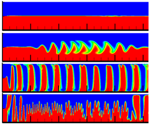
The third mode is implemented using the values of the parameters marked in table 1 with a cyan colour background. The magnetic fluid layer breaks into separate vertical plugs that block the channel in this mode, where the waves’ amplitude grows so quickly that they reach the channel walls very close to the point of flow confluence (figure 5).

Figure 5. The case NH = 1.57 ⋅ 105, Re = 0.0108 for (a) t = 0.233, (b) t = 0.5, (c) t = 0.617. The layer of magnetic fluid is broken into separate plugs. The onset and propagation of waves in this mode is demonstrated by supplementary movie 3.

The resulting plugs move collectively from left to right while remaining almost vertical under the influence of the flow. As can be observed, waves are created not only at the channel's left-side point of flow confluence but also at its right-side outflow. This is due to the magnetic field's non-uniformity, which develops since there is not a channel section that equalizes the magnetic field as there is at the inlet. The magnetic field at the channel's outlet corners becomes non-uniform, which results in the channel's diffusion front being deformed. As can be observed from the data shown below, plugs induce a noticeable increase in the period of oscillations of the diffusion front at the area of flow confluence.

Magnetostatic instability can develop at the interface where immobile magnetic and non-magnetic fluids contact, as demonstrated in Krakov et al. (Reference Krakov, Zakinyan and Zakinyan2021). With the above-described mechanisms of instability, perturbations developed at the point where the flows converge, and the waves travelled along the diffusion front. As magnetostatic instability occurs, disturbances start to appear and grow along the entire interface. These two mechanisms concurrently disrupt the diffusion front (figure 6) at sufficiently high magnetic field values, which triggers the rapid production of plugs. In this instance, the magnetostatic instability has a small wavelength at first (figure 6b) (the smaller, the greater the magnetic field strength; Krakov et al. Reference Krakov, Zakinyan and Zakinyan2021). But the peaks that occur develop quickly, combine to form larger structures and eventually cause plugs to appear all the way along the channel. The cells in table 1 that match this fourth mode are indicated by a pink colour.

Figure 6. The case NH = 7.85 ⋅ 105, Re = 0.0108 and panels show (a) t = 0.033, (b) t = 0.05, (c) t = 0.67, (d) t = 0.78. Wave and magnetostatic instabilities of the diffusion front emerge concurrently. The onset and propagation of waves in this mode is demonstrated by supplementary movie 4.

The analysis of table 1 shows that the NH parameter is not the single factor that affects the flow regime. In fact, wave instability of the diffusion front is seen at ${N_H} = 157\;080\;(H = 1\;\textrm{kA}\;{\textrm{m}^{ - 1}},\;U = {10^{ - 4}}\;\textrm{m}\;{\textrm{s}^{ - 1}})$, and magnetostatic instability appears at ${N_H} = 109\;956$ ($H = 7\;\textrm{kA}\;{\textrm{m}^{ - 1}},\;U = {10^{ - 3}}\;\textrm{m}\;{\textrm{c}^{ - 1}}$; see cells with solid red borders in table 1, and the same situation with the cells with dashed red borders). If the NH parameter were the only factor, this could not be the case. This problem was solved by analysing the change in the phase velocity of the waves that arise at the point of confluence of the flows and propagate along the diffusion front. The leading-edge velocity of the wave packet travelling along the diffusion front was used to calculate the phase velocity (figure 3). A function of the form ${u_p} = f(N_H^mR{e^n})$ was used to fit the data collection. The least squares method of analysis revealed that the optimal values are m = 1 and n = 1/2. The function f in this instance takes the form (figure 7)

(2.33)\begin{equation}{u_p} = 5.522\boldsymbol{\cdot }{10^{ - 4}}{N_H}\sqrt {Re} - 0.2854.\end{equation}

The square of the linear correlation coefficient for this function is R 2 = 0.9728, indicating a high probability that the only parameter affecting how waves move along the diffusion front is the product ${N_H}\sqrt {Re} $.

Figure 7. Dependence of phase velocity on the parameter ${N_H}\sqrt {Re} $.

An interesting issue is the passage to the limit with a decrease in the flow velocity to the instability parameters of immobile fluids. Instability of an immobile fluid was studied earlier in Erglis et al. (Reference Erglis, Tatulcenkov, Kitenbergs, Petrichenko, Ergin, Watz and Cebers2013) and Krakov et al. (Reference Krakov, Zakinyan and Zakinyan2021). This question was asked by Professor A. Cebers during the presentation of this work at the 16th International Conference on Magnetic Fluids in Granada, June 2023. Quantitative comparison of the results is very difficult due to the reasons given in Krakov et al. (Reference Krakov, Zakinyan and Zakinyan2021). The fact that the results correspond qualitatively is shown in figure 6(b), which shows the development of an instability similar to that studied in these works. In addition, it follows from the above expression for the phase velocity that, as the flow velocity decreases (Re → 0), ${N_H}\sqrt {Re} = G{r_m}/\sqrt {Re} \to \; \infty $, i.e. the phase velocity must tend to infinity. This can be interpreted as the instability of the diffusion front must occur simultaneously along the entire diffusion front. This happens both in the case of immobile fluids and in the case of flows at high values of the parameter ${N_H}\sqrt {Re} $ (figure 6b).

Table 2, which displays the values of this parameter and the flow modes similarly to table 1, supports the hypothesis that the parameter determining the properties of the waves and the instability of the diffusion front at the interface of two flows is the product ${N_H}\sqrt {Re} $.

Table 2. ${N_H}\sqrt {Re} $ parameter values and flow modes.

Table 2 demonstrates that, as the parameter ${N_H}\sqrt {Re} $ increases, wave modes change consecutively. The data that are now accessible are incomplete, which prevents us defining the precise essential values for the transition from one flow mode to another. This is due to the extraordinarily long run times of individual variants. Nevertheless, the following can be roughly determined for these critical values:

  • ${N_H}\sqrt {Re} \lesssim 4000$ – there are no waves, the mixing of flows occurs only due to diffusion;

  • $4000\lesssim {N_H}\sqrt {Re} \lesssim 12\;000$ – there is a wave mode, the amplitude of the waves does not reach the boundaries of the channel;

  • $12\;000\lesssim {N_H}\sqrt {Re} \lesssim 25\;000$ – there is a plug mode, the source of waves is the point of confluence of the flows;

  • ${N_H}\sqrt {Re} \gtrsim 25\;000$ – there is a plug mode, and the developing magnetostatic instability as well as the point of confluence of the flows are the sources of waves.

Since ${N_H}\sqrt {Re} = G{r_m}/\sqrt {Re} $, it should be noted that, for a fixed value of ${N_H}\sqrt {Re} $, an increase in the flow velocity (Reynolds number) leads to an increase in the critical magnetic field, which controls the transition from one mode to another.

Near the point of confluence of the two flows, the diffusion front oscillates periodically, as is evident from figure 4. The parameter ${N_H}\sqrt {Re} $ affects the oscillation period's value (figure 8). Between the plug mode and the wave mode, this dependence is very different. The diffusion front's oscillation period rapidly rises upon transition to the plug mode. Perhaps this is a result of the pressure buildup that is required to push the plugs through with the flow.

Figure 8. Dependence of oscillation period on parameter ${N_H}{\sqrt {Re} ^{0.175}}$. • – wave mode, $\blacklozenge$ – plug mode.

3. Conclusion

The two-dimensional flow of miscible magnetic and non-magnetic fluids at equal flow rates has been investigated. Fluids flow in a flat, horizontal channel with a width of less than 100 microns, which means low Reynolds numbers. An external magnetic field is uniform and vertically directed. On the diffusion front between magnetic and non-magnetic fluids, four flow and wave generation modes are identified. The parameter ${N_H}\sqrt {Re} $ controls the transition between one mode and another. At ${N_H}\sqrt {Re} \; \mathrm{\ \mathbin{\lower.3ex\hbox{$\buildrel< \over {\smash{\scriptstyle\sim}\vphantom{_x}}$}}\ }4000$, the diffusion front remains flat, as in the absence of a magnetic field; in the range $4000\mathrm{\ \mathbin{\lower.3ex\hbox{$\buildrel< \over {\smash{\scriptstyle\sim}\vphantom{_x}}$}}\ }{N_H}\sqrt {Re} \mathrm{\ \mathbin{\lower.3ex\hbox{$\buildrel< \over {\smash{\scriptstyle\sim}\vphantom{_x}}$}}\ }12\;000$, waves propagate on the diffusion front, the wave crests do not reach the channel walls. At ${N_H}\sqrt {Re} \mathrm{\ \mathbin{\lower.3ex\hbox{$\buildrel> \over {\smash{\scriptstyle\sim}\vphantom{_x}}$}}\ }12\;000$, the wave crests reach the channel walls and the magnetic fluid layer breaks into separate plugs. At the same time, in the range of values $12\;000\mathrm{\ \mathbin{\lower.3ex\hbox{$\buildrel< \over {\smash{\scriptstyle\sim}\vphantom{_x}}$}}\ }{N_H}\sqrt {Re} \mathrm{\ \mathbin{\lower.3ex\hbox{$\buildrel< \over {\smash{\scriptstyle\sim}\vphantom{_x}}$}}\ }25\;000$, waves arise at the point of confluence of the flows of magnetic and non-magnetic fluids, and at ${N_H}\sqrt {Re} \mathrm{\ \mathbin{\lower.3ex\hbox{$\buildrel> \over {\smash{\scriptstyle\sim}\vphantom{_x}}$}}\ }25\;000$, the magnetostatic instability of the diffusion front develops, previously studied in Krakov et al. (Reference Krakov, Zakinyan and Zakinyan2021). The transition from the wave to the plug flow mode is accompanied by a sharp increase in the oscillation period of the diffusion front near the point of flow confluence.

Supplemental movies

Supplementary movies are available at https://doi.org/10.1017/jfm.2023.608.

Funding

M.K. acknowledges the support by the Ministry of Higher Education of the Republic of Belarus (project No 20212019).

Declaration of interests

The author reports no conflict of interest.

References

Cai, G., Xue, L., Zhang, H. & Lin, J. 2017 A review on micromixers. Micromachines 8, 274300.CrossRefGoogle ScholarPubMed
Cebers, A. & Igonin, M. 2002 Convective instability of magnetic colloid and forced Rayleigh scattering experiment. Magnetohydrodynamics 38, 265270.Google Scholar
Chen, C.-Y., Yang, Y.-S. & Miranda, J.A. 2009 Miscible ferrofluid patterns in a radial magnetic field. Phys. Rev. E 80, 016314.CrossRefGoogle Scholar
Eckert, K., Acker, M. & Shi, Y. 2004 Chemical pattern formation driven by a neutralization reaction. I. Mechanism and basic features. Phys. Fluids 16, 385399.CrossRefGoogle Scholar
Erglis, K., Tatulcenkov, A., Kitenbergs, G., Petrichenko, O., Ergin, F.G., Watz, B.B. & Cebers, A. 2013 Magnetic field driven micro-convection in the Hele-Shaw cell. J. Fluid Mech. 714, 612633.CrossRefGoogle Scholar
Islam, A., Sharif, M.A.R. & Carlson, E.C. 2013 Density driven (including geothermal effect) natural convection of carbon dioxide in brine saturated porous media in the content of geological sequestration. In Proceedings of the Thirty-Eighth Workshop on Geothermal Reservoir Engineering, Stanford University, Stanford, California, February 11–13, SGP-TR-198. Available at: https://pangea.stanford.edu/ERE/pdf/IGAstandard/SGW/2013/Islam.pdf.Google Scholar
Kitenbergs, G. & Cbers, A. 2019 Rivalry of diffusion, external field and gravity in microconvection of magnetic colloids. J. Magn. Magn. Mater. 498, 166247.CrossRefGoogle Scholar
Kitenbergs, G., Tatulĉenkovs, A., Erglis, K., Petrichenko, O., Perzinski, R. & Cbers, A. 2015 Magnetic field driven micro-convection in the Hele-Shaw cell: the Brinkman model and its comparison with experiment. J. Fluid Mech. 774, 170191.CrossRefGoogle Scholar
Kitenbergs, G., Tatuļčenkovs, A., Puķina, L. & Cbers, A. 2018 Gravity effects on mixing with magnetic micro-convection in microfluidics. Eur. Phys. J. E 41, 111.CrossRefGoogle ScholarPubMed
Krakov, M.S. 2020 Mixing of miscible magnetic and non-magnetic fluids with a rotating magnetic field. J. Magn. Magn. Mater. 498, 166186.CrossRefGoogle Scholar
Krakov, M.S., Zakinyan, A.R. & Zakinyan, A.A. 2021 Instability of the miscible magnetic/ non-magnetic fluid interface. J. Fluid Mech. 913, A30-1A30-29.CrossRefGoogle Scholar
Li, H., Kao, C.-Y. & Wen, C.-Y. 2018 Labyrinthine and secondary wave instabilities of a miscible magnetic fluid drop in a Hele-Shaw cell. J. Fluid Mech. 836, 374396.CrossRefGoogle Scholar
Maiorov, M.M. & Tsebers, A.O. 1983 Magnetic microconvection on the diffusion front of ferroparticles. Magnetohydrodynamics 19, 376380.Google Scholar
Maleki, M.A., Soltani, M., Kashaninejad, N. & Nguyen, N.-T. 2019 Effects of magnetic nanoparticles on mixing in droplet-based microfluidics. Phys. Fluids 31, 032001.CrossRefGoogle Scholar
Patankar, S. 1980 Numerical Heat Transfer and Fluid Flow. Hemisphere Series on Computational Methods in Mechanics and Thermal Science. Taylor & Francis.Google Scholar
Saadat, M., Ghassemi, M. & Shafii, M.B. 2020 Numerical investigation on the effect of external varying magnetic field on the mixing of ferrofluid with deionized water inside a microchannel for lab-on-chip systems. Energy Sources A: Recovery Util. Environ. Eff. 113.CrossRefGoogle Scholar
Shanko, E.-S., van de Burgt, Y., Anderson, P.D. & den Toonder, J.M.J. 2019 Microfluidic magnetic mixing at low Reynolds numbers and in stagnant fluids. Micromachines 10, 731.CrossRefGoogle ScholarPubMed
Shliomis, M.I. & Smorodin, B.L. 2002 Convective instability of magnetized ferrofluids. J. Magn. Magn. Mater. 252, 197202.CrossRefGoogle Scholar
Vand, V. 1948 Viscosity of solutions and suspensions. I. Theory. J. Phys. Colloid Chem. 52, 277299.CrossRefGoogle Scholar
Vislovich, A.N. 1990 Phenomenological equation of static magnetization of magnetic fluids. Magnetohydrodynamics 26, 178183.Google Scholar
Yang, R.-J., Hou, H.-H., Wang, Y.-N. & Fu, L.-M. 2016 Micro-magnetofluidics in microfluidic systems: a review. Sensors Actuators B 224, 115.CrossRefGoogle Scholar
Zhu, G.P. & Nguen, N.T. 2012 Rapid magnetofluidic mixing in a uniform magnetic field. Lab on a Chip 12, 47724780.CrossRefGoogle Scholar
Figure 0

Figure 1. Geometry of the problem and calculation domain.

Figure 1

Table 1. NH parameter values and flow modes (different colours, see text).

Figure 2

Figure 2. Diffusion front after t = 5.56 (dimensional time is 2000 second). Here, NH = 3142, Re = 1.08.

Figure 3

Figure 3. The diffusion front's wave propagation pattern. Here, NH = 15 708, Re = 0.108, and panels show (a) t = 1.05, (b) t = 2.67, (c) t = 3.98. The position of the maximum that occurred first is shown by the arrow. The waves’ group velocity is significantly lower than their phase velocity. The onset and propagation of waves in this mode is demonstrated by supplementary movie 1 available at https://doi.org/10.1017/jfm.2023.608.

Figure 4

Figure 4. The case NH = 10996, Re = 1.08, t = 4.07. The waves’ crests reached the channel walls, the mixing intensity grew and the frequency of oscillations of the diffusion front near the point of confluence of the flows increased. The onset and propagation of waves in this mode is demonstrated by supplementary movie 2.

Figure 5

Figure 5. The case NH = 1.57 ⋅ 105, Re = 0.0108 for (a) t = 0.233, (b) t = 0.5, (c) t = 0.617. The layer of magnetic fluid is broken into separate plugs. The onset and propagation of waves in this mode is demonstrated by supplementary movie 3.

Figure 6

Figure 6. The case NH = 7.85 ⋅ 105, Re = 0.0108 and panels show (a) t = 0.033, (b) t = 0.05, (c) t = 0.67, (d) t = 0.78. Wave and magnetostatic instabilities of the diffusion front emerge concurrently. The onset and propagation of waves in this mode is demonstrated by supplementary movie 4.

Figure 7

Figure 7. Dependence of phase velocity on the parameter ${N_H}\sqrt {Re} $.

Figure 8

Table 2. ${N_H}\sqrt {Re} $ parameter values and flow modes.

Figure 9

Figure 8. Dependence of oscillation period on parameter ${N_H}{\sqrt {Re} ^{0.175}}$. • – wave mode, $\blacklozenge$ – plug mode.

Krakov Supplementary Movie 1

Wave mode. NH = 15708, Re = 0.108.

Download Krakov Supplementary Movie 1(Video)
Video 848.8 KB

Krakov Supplementary Movie 2

Wave mode. NH = 10996, Re = 1.08.

Download Krakov Supplementary Movie 2(Video)
Video 2.3 MB

Krakov Supplementary Movie 3

Plug mode with the hydrodynamic source of the perturbations. NH = 1.57⋅105, Re = 0.0108

Download Krakov Supplementary Movie 3(Video)
Video 410.4 KB

Krakov Supplementary Movie 4

Plug mode with the hydrodynamic source of the perturbations. NH = 7.85⋅105, Re = 0.0108.

Download Krakov Supplementary Movie 4(Video)
Video 962.5 KB