Introduction
Largely because of its influence on the sliding of temperate glaciers, the mode of subglacial water flow has attracted considerable attention among glaciologists. Theoretical considerations of subglacial hydrology have been presented by Reference RöthlisbergerRöthlisberger (1972), Reference ShreveShreve (1972), Reference WeertmanWeertman (1972), Reference MathewsMathews (1973), and Reference NyeNye (1973, Reference Nye1976). Field studies of jökulhlaups (e.g. Reference BezingeBezinge and others, 1973; Reference MathewsMathews, 1973), of salt or dye tracers injected into ice-dammed lakes, supraglacial streams, and moulins (e.g. Reference MeierMeier, 1965; Reference StenborgStenborg, 1969, Reference Stenborg1973; Reference FisherFisher, 1973), of water-pressure variations in glacier bore holes (e.g. Reference MathewsMathews, 1964; Reference Vivian and ZumsteinVivian and Zumstein, 1973; Reference HodgeHodge, 1976, Reference Hodge1979; Reference Kamb, Kamb, Engelhardt and HarrisonKamb and others, 1979; Reference Röthlisberger, Röthlisberger, Iken and SpringRöthlisberger and others, 1979), and of vertical surface movements (Reference Iken, Iken, Flotron, Haeberli and RöthlisbergerIken and others, 1979) have yielded important information on glacial hydrology. However, little is known of several key issues, including the degree of channelization of subglacial water and the geometry of subglacial channels. Through a detailed study of surficial features of recently deglaciated bedrock surfaces, we have gained considerable insight into these issues. In this paper, we describe the technique and summarize the results of this study.
Field Setting and Techniques
A detailed map was compiled of the topography and surficial features of an area of approximately 5 000 m2, representative of an extensive exposure of recently deglaciated limestone bedrock near the terminus of Blackfoot Glacier, Glacier National Park, Montana, U.S.A. Blackfoot Glacier, which is approximately 2 km wide and 1.5 km long, occupies a north-east-facing cirque and extends from the continental divide, at an elevation of approximately 2 900 m, to the present terminus at an elevation of approximately 2 100 m. The mapped surface is slightly irregular and dips gently (c. 10°) down-glacier. It roughly parallels the bedding of the underlying stromatolitic limestone, a member of the Precambrian Helena Dolomite (Reference RossRoss, 1959).
Plane table and alidade were used to establish primary control points and to trace elevation contours. Grids were laid out around each primary control point for secondary control. Map features are located with an accuracy of 30–40 cm with elevations accurate to c. 10 cm.
The former glacier bed was subdivided into domains characterized by distinct surface morphologies that reflect different degrees of modification by glacial abrasion, water erosion, chemical dissolution, and precipitation. By mapping the present configuration of these geomorphic domains, it is possible to reconstruct in considerable detail the spatial pattern of the formerly active subglacial processes of cavitation, water flow, chemical alteration, and abrasion. There were no readily apparent variations in the rock type within the study area and it appears unlikely that marked lateral variations would occur parallel to the bedding in this carbonate unit. Therefore, the nature of the bedrock is assumed to have negligible influence on the spatial distribution and geometry of the mapped glacio-geomorphic units. Six such units were recognized and mapped; they are described below.
Description of Surface Features
Chemically altered areas
These areas are distinguished by the presence of abundant, furrowed, subglacially precipitated calcite deposits on the down-glacier sides of bedrock protuberances (Fig. 1). These deposits are formed during the refreezing of melt waters associated with active sliding. Their morphology, particularly the spicules and furrows aligned parallel to the former ice-flow direction, suggests that ice and rock were practically in contact at the sites of formation, being separated by a very thin film of water (Reference HalletHallet, 1976, Reference Hallet1979).
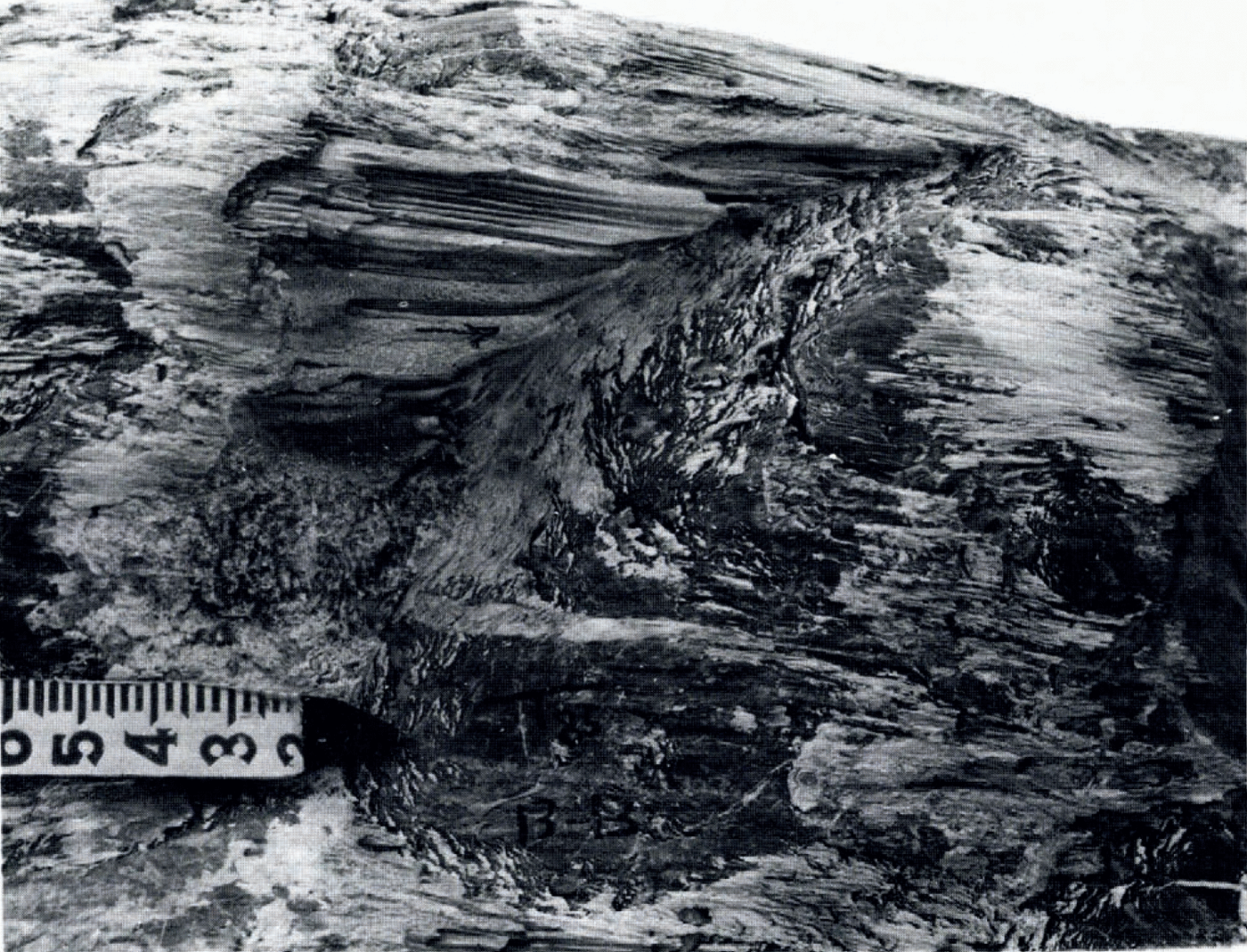
Fig. 1. Nearly vertical chemically altered surface. Note the CaC03 spicules parallel and solutional furrows transverse to former ice-flow direction (indicated by arrow). Numbered divisions on rule are 0.1 ft (3 cm).
Associated with the subglacial precipitates are series of dissolutional furrows, generally transverse to the former ice-flow direction, on the up-glacier sides of bedrock protuberances. These are on the order of 1–5 mm deep and spaced at an interval of 5–15 mm.
In some chemically altered areas, the bedrock comprises systematic arrays of closely spaced protuberances. These bedrock highs are characteristically outlined up-glacier by crescentic solutional furrows several millimeters deep and concave down-glacier, laterally by erosional grooves several tens of millimeters in depth and width, and down-glacier by subglacial precipitate (Fig. 2). Striations are often present on the upper surfaces of the protuberances which may correspond to relatively resistant parts of the bedrock, probably related to the stromatolitic nature of the limestone. Their widths range from c. 15 to 45 cm.
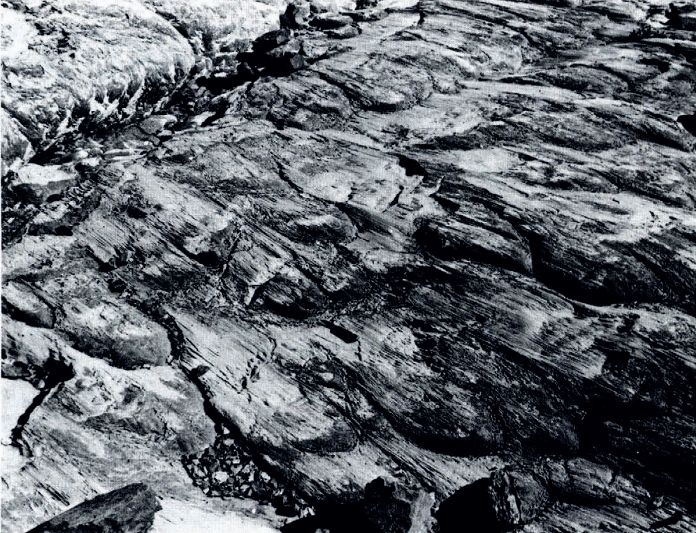
Fig. 2. Chemically altered surface, with systematic arrays of closely-spaced bedrock-protuberances outlined by crescentic erosional grooves. See text for detailed description. Direction of former ice flow is lower right to upper left. Knife near center provides scale.
Abraded areas
These are distinguished by the scarcity of both subglacial precipitate and solutional furrows, and by an abundance of striations. The abraded areas occur close to one another in 5–10m wide zones that nearly parallel the former ice-flow direction and disregard the topography. They are separated by broader zones primarily affccted by chemical processes (Fig. 3). Occasional striated linear depressions, resembling shallow “plastically molded surfaces" or p-forms (Reference DahlDahl, 1965), are present in the abraded areas.
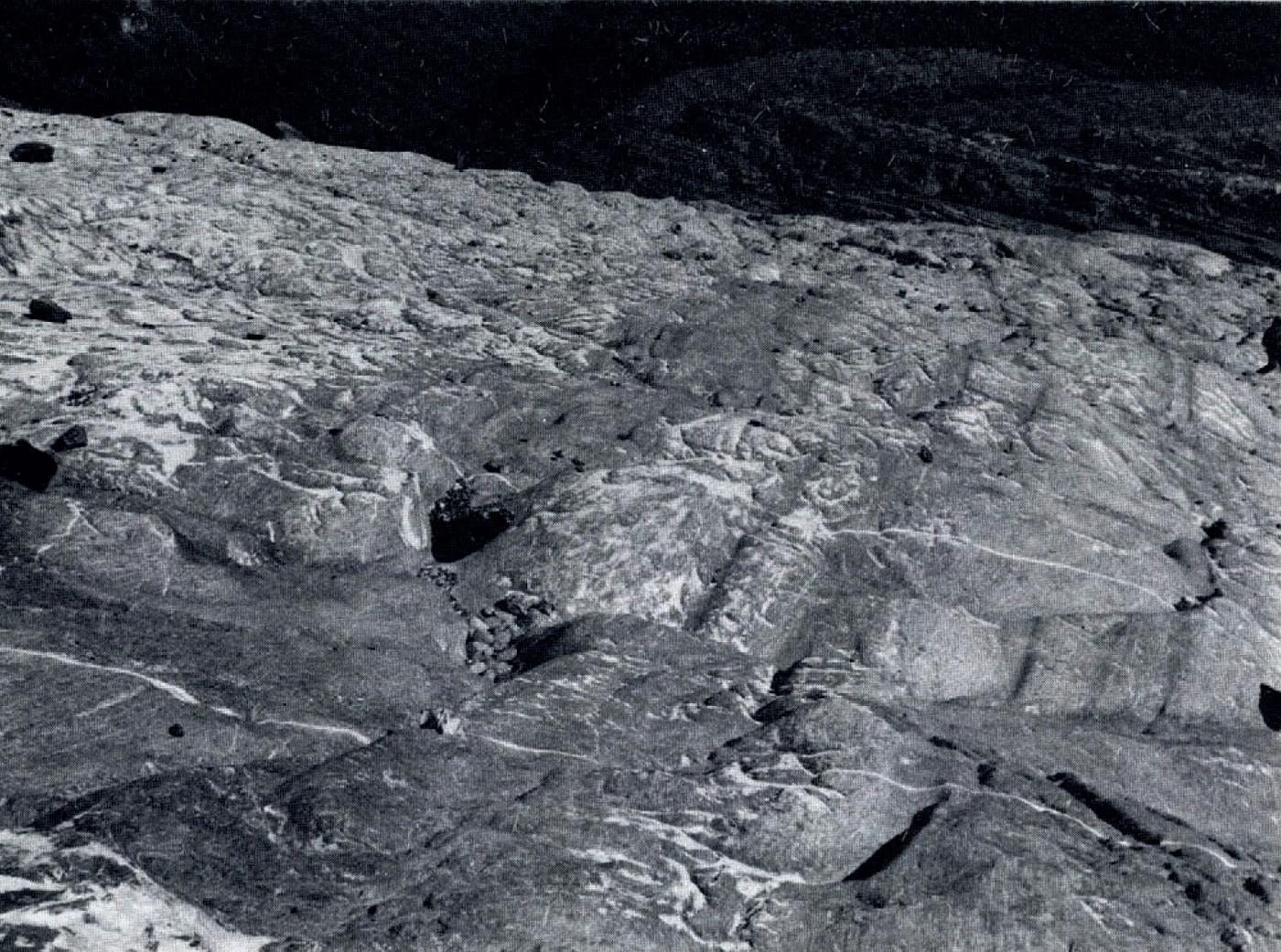
Fig. 3. Down-glacier view of abraded zones and chemically altered zones with lightly-colored subglacially-formed carbonate deposits. Rock-filled depression slightly below center is 0.5m wide
Cavities
Areas down-glacier of bedrock highs or breaks in bed slope often exhibit extensive solutional features and lack evidence of ice contact. These areas, which generally are steeply inclined concavities in the bedrock, have been interpreted as sites of former water-filled subglacial cavities (Fig. 4). These bedrock concavities have a vertical relief of 0.1–1.5 m and tend to be elongated transverse to the former ice-flow direction. Their surfaces tend to be deeply scalloped in an irregular fashion. Adjacent scallops are separated by relatively resistant septa, probably related to argillite-rich partings in the stromalolitic limestone bedrock. These surfaces are quite similar in appearance to those created by the turbulent flow of water on limestone in caves and subaerial environments, including stream channels in front of Blackfoot Glacier. Because of their steep inclinations, many of the scalloped bedrock concavities cannot hold water subaerially; they could experience extensive dissolution only if corrosive water were confined over these areas, as in subglacial cavities.
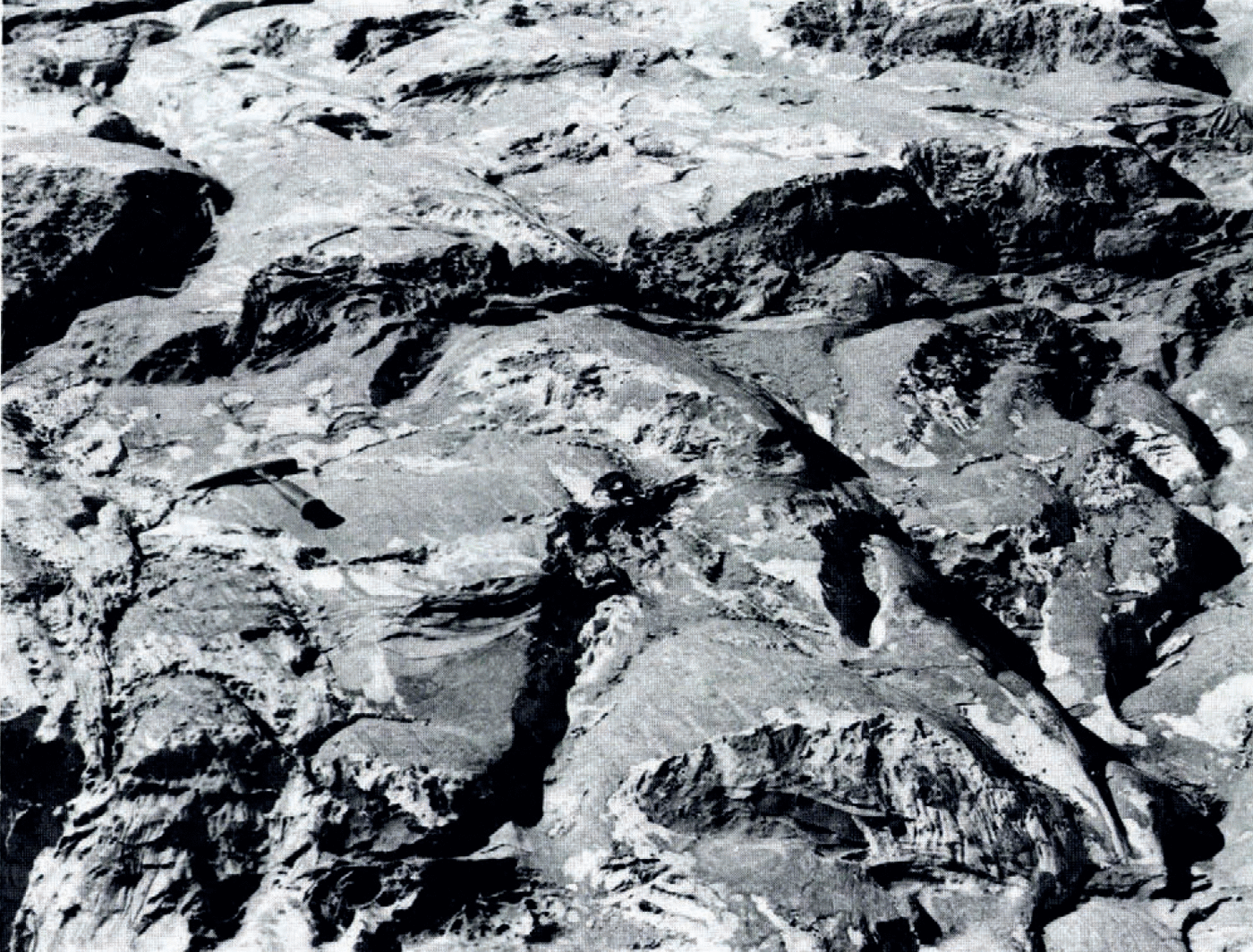
Fig. 4. Interconnected, deeply scalloped cavities and channels. Note argillite partings in limestone bedrock in the corroded cavity at lower center. Handle of hammer points in former ice-flow direction.
Some of these former cavities have a thin discontinuous coating of subglacial precipitate along their peripheries, especially on their up-glacier sides. Such precipitates do not comprise spicules like those in chemically altered areas but rather have relatively featureless surfaces.
Precipitate-filled depressions
These are shallow (c. 50 mm) depressions in the bedrock nearly filled by subglacial precipitate (Fig. 5). As in cavities, the precipitate surface tends to be featureless. Evidence of ice contact is lacking.
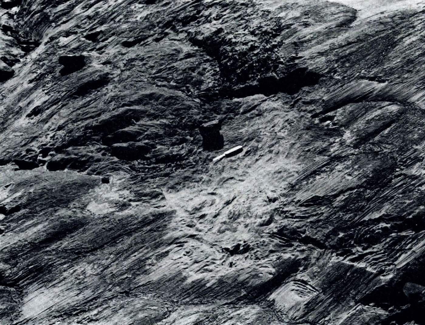
Fig. 5. Precipitate-filled depressions in chemically altered zone. Knife blade points down-glacier.
Although these depressions probably represent former shallow subglacial cavities, they have been arbitrarily distinguished from cavities, as defined above, by their shallowness, their small areal extent (c. 0.5 m2), and their tendency to be equidimensional in map view, rather than elongated transverse to the former ice-flow direction.
Channels
Narrow elongated depressions, typically 50–250 mm deep, 100–200 mm wide, and 2–5 m long, with solutional features probably formed by corrosive running water, are considered to be former subglacial water channels (Fig. 6). (Following Reference WeertmanWeertman’s (1972) usage, these are hereafter called “Nye channels”.) The scalloping characteristic of these channels, as well as of former cavities, resembles the solutional roughness that results from “the interaction of a soluble surface and an adjacent turbulent flow" (Reference Blumberg and CurlBlumberg and Curl, 1974, p. 735). A large fraction of the Nye channels have a thin discontinuous coating of subglacial precipitate, either in the featureless form or, more commonly, as spicules aligned parallel to channel walls (Fig. 6). The presence of the spicules suggests that many channels were occupied at some time, or perhaps intermittently, by basal ice.
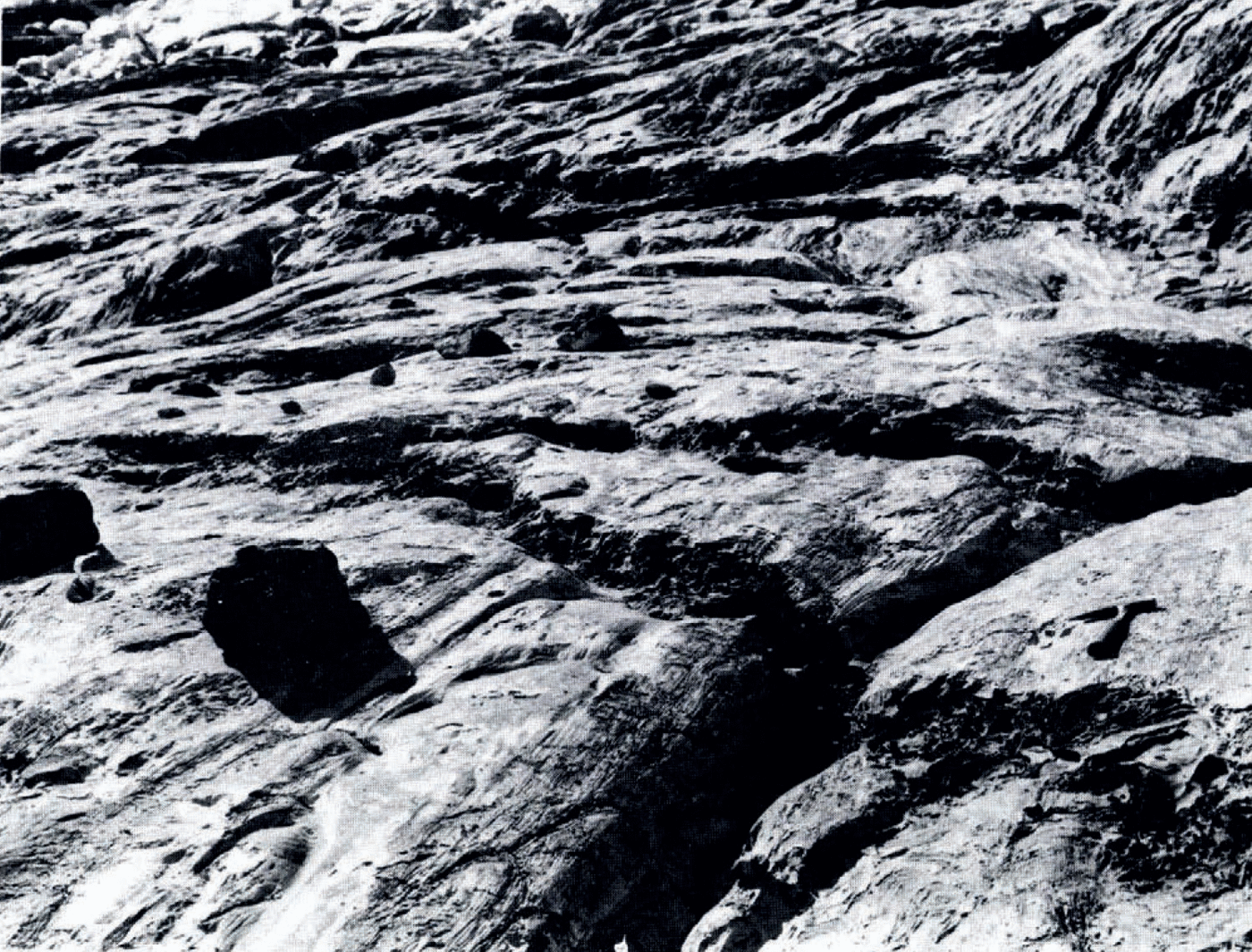
Fig. 6. Former water channels incised in bedrock (Nye channels). Younger, deeply scalloped channel crosses older, chemically altered channel at lower right. Handle of hammer points in former ice-flow direction.
Nye channels do not appear to form an arborescent network; neither the channel density nor the average channel cross-sectional area changes systematically down-glacier. Our map (Fig. 7) shows that Nye channels tend either to nearly parallel the former ice-flow direction or to follow the localbed slope. Counts made on parts of the map indicate that roughly 30–40% of these channels, including many of the longer ones, have a bearing within 10° of the former ice-flow direction and a similar percentage tend to follow the local bed slope.

Fig. 7. Map of the subglacial drainage network.
Karst
These are narrow, deep, linear to sub-linear bedrock depressions formed by dissolution along two sets of joints oblique to the ice-flow direction. They tend to interconnect with underground passages, thereby forming a subterranean drainage network that was and is active. They probably formed in large part subaerially but were modified at least superficially under the glacier.
Map: General Results
Three general results emerge from our mapping. First, the cavities and Nye channels form a practically continuous network of drainage conduits, as shown in Figure 7. Secondly, the degree of cavitation beneath a small cirque glacier can be significant. Approximately 20% of the bed area mapped was not in close contact with the basal ice during much of the glaciation. Thirdly, the bed has a striped appearance, parallel to the former ice-flow direction, with narrow zones affected principally by abrasion separated by broader zones affected principally by chemical processes, as depicted in Figure 8.

Fig. 8. Striped pattern represents abraded areas. Arrows point in local ice-flow direction. Irregular lines represent contours with a 3 ft (c. 0.9 m) interval. Compare with Figure 7.
We stress that our map does not represent an instantaneous picture of conditions at the glacier bed; rather it represents basal conditions averaged over an uncertain length of time, probably several or several tens of years.
Discussion
Approximately 70% of the mapped area consists of chemically altered surfaces traversed by numerous Nye channels. Calcite spicules and transverse furrows characteristic of these chemically altered areas can probably form only if the subglacial water film that separates ice and bedrock is no thicker than several or several tens of micrometers, and the film accommodates little or no through-flowing water (Reference HalletHallet, 1979). In contrast, the solutional roughness and size of Nye channels suggest that much water flowed rapidly through them. The common occurrence of Nye channels within chemically altered zones and, in particular, the lack of any apparent influence of these channels on subglacial chemical processes on adjacent surfaces, as indicated by the distribution of calcite spicules and dissolutional furrows, suggest that there are two relatively independent hydraulic systems at the glacier bed: a thin film, covering most of the bed, which accommodates local regelation melt waters, and a cavity–channel network, which accommodates turbulent through-flowing melt waters. The concept of such a two-fold subglacial hydraulic system was advanced on theoretical grounds by Reference NyeNye (1973) and is compatible with recent field observations by other glaciologists. Reference HodgeHodge (1979) found that the probability of bore holes connecting with the “subglacial water system" (or cavity–channel network, in our interpretation) of South Cascade Glacier, as indicated by bore-hole water levels, varied from 7% to 60%. At Blue Glacier, Reference Kamb, Kamb, Engelhardt and HarrisonKamb and others (1979) observedthat pressurized bore-hole water did not penetrate the layer of drift at the glacier sole. They suggested that areas of direct ice–rock contact provide permeability barriers. These regions, which are not hydraulically connected with subglacial water conduits, may be analogous to the chemically altered areas at Blackfoot Glacier in their lack of through-flowing water. We note, however, that there is practically no till on the recently deglaciated bed of Blackfoot Glacier, and that the pro-glacial drainage system has probably removed little debris; therefore, the former (and present) existence of a widespread drift layer at the sole of Blackfoot Glacier is very unlikely.
One of the particularly intriguing features of the map is the presence of distinct, elongated linear zones characterized by abrasion (Fig. 8). The abundance of striations and the conspicuous scarcity of both subglacially precipitated calcite and associated dissolutional features within these zones suggest that conditions at the ice–rock interface were locally favorable for abrasion and unfavorable for both chemical precipitation and dissolution. Concentrations of debris in the basal ice could locally enhance abrasion but would not necessarily affect chemical processes in the postulated fashion. A mechanism more compatible with our interpretation of the field evidence involves an enhancement of through flow of water in the film along these abraded zones. The gross effect of introducing such enhanced through flow is that the spatial variability of solute concentration in the water tends to be reduced and, hence, local lows and highs of solute concentration needed for subglacial dissolution and precipitation would be thereby reduced (Reference HalletHallet, 1979). However, such through flow of water is constrained to have occurred in an enlarged subglacial sheet rather than in a tunnel in the ice. (Such tunnels have been called Reference Röthlisberger“Röthlisberger” (or “R”) channels by Reference WeertmanWeertman (1972).) Such a tunnel would prevent the debris-laden basal ice from striating the bed; moreover, the bed would probably show the scalloping characteristic of the turbulent channelized flow of corrosive water.
The stability of subglacial sheet flow of water with respect to perturbations in film thickness in the absence of Nye channels, has been examined by J. Walder. Preliminary results of theoretical analysis indicate that such perturbations may grow under certain conditions, with the tendency for flow localization increasing with the pressure gradient and mean sheet thickness.
The source of enhanced flow could also be melt water that locally reaches the glacier bed through moulins or crevasses. The apparent alignment of the laterally zoned part of the former glacier bed and a series of crevasses aligned perpendicular to the glacier front renders this possibility intriguing.
Irrespective of the details of the sheet flow, incised channels must have been important for draining subglacial melt waters. The numerous channels that nearly parallel the former ice-flow direction must be of subglacial origin, for they do not exhibit characteristics typical of subaerially formed channels; arborescence, tendency to follow bed slope, and distinct catchment areas are absent. These channels may be initiated along deep striations or abrasional gouges, which parallel the ice-flow direction. These striations or gouges could act as embryonic Nye channels and collect water from cavities (Reference LliboutryLliboutry, 1979) or from a subglacial water sheet, due to slight lateral pressure gradients in the sheet (Reference WeertmanWeertman, 1972, p. 299–306). The former existence of R channels above these Nye channels appears likely, particularly because R channels are relatively stable when aligned with the ice-flow direction (Reference WeertmanWeertman, 1972, p. 307).
Channels that tend to follow the bed slope cannot be, in general, of post-glacial origin, for many are coated with subglacially formed precipitate. However, their possible pre-glacial existence is not precluded.
Density of channels and cavities
A knowledge of the melt-water discharge of individual subglacial channels and of the glacier as a whole permits an estimation of the number of channels active simultaneously. The steady-state discharge of channels of circular cross-section, as a function of channel radius and pressure gradient, is shown in figure 3 of Reference WeertmanWeertman (1972, p. 294). Approximating the mapped channels by conduits of semi-circular cross-section with radii of c. 50–150 mm, and for reasonable values of pressure gradient (10–3–10–2 bar m–1), the discharge of each channel when full is about 104–105 m3a–1. For a glacier of 1–10 km2 (106–107 m2) bed surface area, sliding at 10–80 m a–1, a range that includes the measured terminus velocity of 15 m a–1, the total discharge during periods of no surface melting is also about 104–105 m3 a–1 (cf. Reference WeertmanWeertman, 1972, fig. 4, p. 295). This value is based on the assumption that all melt water produced by geothermal heating and sliding friction, estimated to be on the order of 1–3 cm a–1 (10–30 mm a–1), flows at the glacier bed. Thus, it is clear that during times of no surface melting, practically all the Nye channels beneath Blackfoot Glacier must have been inactive.
During periods of substantial surface melting, if a considerable amount of supraglacial melt water reaches the glacier bed either through moulins or crevasses (Reference StenborgStenborg, 1973; Reference WeertmanWeertman, 1973) or by percolating through veins (Reference ShreveShreve, 1972; Reference Nye and FrankNye and Frank, 1973; Reference Raymond and HarrisonRaymond and Harrison, 1975), the effective ice thickness melted at the bed will increase dramatically. Although there are no data available on the melt-water discharge of Blackfoot Glacier, a useful comparison may be made with the data for Peyto Glacier, about 450 km to the north-west in the Canadian Rockies (Reference DerikxDerikx, 1973, fig. 6, p. 37). When averaged over the entire glacier, the average summer melting-rate can be computed to be 5–10 m a–1. For a glacier with the same bed surface area and sliding velocity as mentioned above, the total discharge with such a melting-rate would be ≥107 m3 a–1 (cf. Reference WeertmanWeertman, 1972, fig. 4, p. 295). This flow could be accommodated by several hundred channels of the size mapped. Given the lateral spacing of Nye channels (typically ≤5 m), the width of the glacier (about 2 km), and the probable existence of R tunnels, it appears that the drainage system could accommodate all melt waters, even during periods of high surface melting.
Reference HaefeliHaefeli (1970, p. 208) and Reference WeertmanWeertman (1972, p. 322) have calculated that moulins and R tunnels, if water-free and under ≥100 m of ice, will shrink in radius by at least 90% during a single cold season. These calculations, which should also be roughly correct for the roof collapse of Nye channels, are consistent with the field evidence suggestive of infilling of the majority of these channels by ice. In fact, some Nye channels must have been modified by ice contact for substantial periods of time, as indicated by the thickness of the coating of calcite spicules (up to several millimeters) and the rate of formation of these spicules (c. 0.1 mm a–1, according to Reference HalletHallet (1979)). Furthermore, cross-cutting relationships (Fig. 6) between Nye channels establish that some of the channels are younger than others. Thus, Reference HaefeliHaefeli’s (1970, p. 208) conjecture that “the subglacial circulatory system must … (if it does not remain water-filled) be reconstituted each year" is consistent with the results of our studies at Blackfoot Glacier.
We conclude that the system of channelized drainage at the glacier bed must have evolved during glaciation. Nye channels formed, drained subglacial waters for a time, then were abandoned by melt water and occupied by ice. A truly arborescent and continuous system of Nye channels did not become established under Blackfoot Glacier. Flow along discontinuous segments of the channel and cavity network may have taken place through a subglacial film (Reference LliboutryLliboutry, 1969, p. 953) or R tunnels (Reference LliboutryLliboutry, 1976, p. 156), or in few instances, through karst passages.
Summary
We have demonstrated that detailed mapping of recently deglaciated bedrock can disclose considerable information on the mode of flow of water at the ice–rock interface. The principal results of this study are:
-
A practically continuous network of interconnecting subglacial channels and cavities exists and can more than accommodate the expected water flow; there seems to be little or no need for a thick subglacial water film. Such a film may be unstable beneath this steep cirque glacier.
-
About 80% of the sole of Blackfoot Glacier conformed to the bed closely, the ice being separated from the bed by a very thin water film. The water along these areas of close ice–rock contact seems to have been largely independent of that in the former channel network. Such areas may correspond to the hydraulically isolated areas often encountered by bore holes drilled to the base of glaciers (Reference HodgeHodge, 1979; Reference Kamb, Kamb, Engelhardt and HarrisonKamb and others, 1979).
-
The subglacial channels incised in the bedrock do not appear to form an arborescent pattern of numerous small channels merging into larger ones. Rather, channel widths are all within a narrow range of c. 0.1–0.3 m. Many of the channels only drained water temporarily, perhaps intermittently; when inactive, they were filled with actively sliding basal ice.
Acknowledgements
We are very grateful to R. Anderson, A. Heyneman, and R. Stein for their vital contributions to both the field studies and later discussions. The generous co-operation of the United States National Park Service rendered the field work possible and is greatly appreciated. Support for this work was provided by National Science Foundation Grant EAR77-13631 and to one of us (Walder) by the Shell Companies Foundation.
Discussion
D. Thompson: Because you have mapped such an extensive number of these subglacial channels and because they seem to align preferentially in the ice-flow direction rather than down the bedrock slope only, it appears that you might be able to reconstruct either previous ice thicknesses or basal shear stress. The water channels must be aligned roughly perpendicular to the equipotential surfaces which existed subglacially. Hence, by assuming a model ice thickness, you should be able to calculate the basal shear stress necessary, or conversely, assuming some basal shear stress, you should be able to calculate the ice thickness which is necessary to maintain the equipotential surfaces at an angle with respect to the actual bedrock topography.
J. Walder: I had not previously considered this possibility but it is an intriguing one. Bed-spectra measurements by Professor Hallet at Blackfoot Glacier may give us some notion of the shear stress. Geological constraints, such as knowing the location of the moraines, should also allow us some qualitative control for estimating paleothicknesses of the glacier ice.
C. C. Smart: Where abundant rock material is found in basal ice flowing over limestone, these precipitates are seldom found. It seems possible that the chemical processes involved in regelation may not be manifest in this situation.
Walder: The correlation of the spatial variability of basal debris content and subglacial precipitate is uncertain. Recent observations at Castleguard Glacier in Alberta of a fairly even precipitate distribution on a recently deglaciated surface, even though the till is clearly concentrated in stripes paralleling the former ice flow, suggest that debris content does not control precipitation. We believe that the controlling factor is the extent of through flow of subglacial melt water.
Smart: Remnants of subglacial conduits have been observed where flow must have been up and down-slope. These systems appear to be water-filled and flow under hydrostatic head.
Walder: Subglacial channels may certainly follow routes impossible were they subaerial. In particular, channels which appear to have drained subglacial cavities may follow unusual routes, possibly due to high water pressure in these cavities.


