Introduction
Over the past several decades, transition metal carbides (TMCs) have attracted much attention due to their unique physicochemical properties and important applications such as low friction interfaces [Reference Sánchez-López, Dominguez-Meister, Rojas, Colasuonno, Bazzan and Patelli1, Reference Martínez-Martínez, López-Cartes, Fernández and Sánchez-López2], corrosion protection layers [Reference Voevodin and Zabinski3], fuel cell electrodes [Reference Wang, Xu, Jin, Chen and Wang4, Reference Fan, Peng, Ye, Zhou and Guo5, Reference Xiong, Guo, Guo, Li, Zhao, Chen, Liu and Wang6], biomedical component [Reference Yu, Yang, Li, Ding, Zhang, Yousaf, Lin, Pang, Wei, Xu, Sheng, Li, Li, Zhao and Hou7, Reference Vitu, Polcar, Cvrcek, Novak, Macak, Vyskocil and Cavaleiro8], and catalysts [Reference Yang, Ma, Chen, Holmen and Davis9]. Generally, the transition metal elements have significant effects on the structure and chemical bonding of binary TMCs [Reference Jansson and Lewin10]. For example, the early transition metals such as Ti, V, and Zr tend to generate strong metal–carbon bonds, which usually have NaCl-type structure. On the other hand, the later transition metals such as Fe, Co, and Ni form weak metal–carbon bonds, demonstrating more complex structures. In the Fe–C system, the carbon can be found in and form various iron carbide phases, including Fe5C2, Fe2C, Fe7C3, Fe3C, and Fe23C6 [Reference Hui, Chen, Xie and Li11]. For these weak carbide formers, the formation enthalpy is less negative or even positive, so these compounds are thermodynamically unstable. Iron carbide is a particularly important TMC and has promising applications in drug delivery [Reference Yu, Yang, Li, Ding, Zhang, Yousaf, Lin, Pang, Wei, Xu, Sheng, Li, Li, Zhao and Hou7], hyperthermia [Reference Tang, Zhen, Yang, Wang, Cowger, Chen, Todd, Hekmatyar, Zhao, Hou and Xie12], and magnetic storage media [Reference Morjan, Alexandrescu, Scarisoreanu, Fleaca, Dumitrache, Soare, Popovici, Gavrila, Vasile, Ciupina and Popa13]. In addition, iron carbide was recently reported to have great potentials for both hydrogen evolution reaction (HER) [Reference Fan, Peng, Ye, Zhou and Guo5] and COx hydrogenation [Reference Yang, Zhao, Hou and Ma14], perhaps because iron is an earth-abundant element with promising catalytic activity. However, prior research on the production of iron carbide is still limited compared with iron metal, iron oxide, and iron sulfide. Commonly used methods for the production of bulk and amorphous iron carbides include solution chemistry method [Reference Yang, Zhao, Huang, Chu, Tang, Ju, Wang, Hou and Gao15], ball milling [Reference Chaira, Mishra and Sangal16], physical vapor deposition [Reference Jouanny, Demange, Ghanbaja and Bauer-Grosse17], and chemical vapor deposition [Reference Krisyuk, Gleizes, Aloui, Turgambaeva, Sarapata, Prud’Homme, Senocq, Samélor, Zielinska-Lipiec, de Caro and Vahlas18]. Among them, atomic layer deposition (ALD) has recently attracted much attention for being able to fabricate high-quality nanomaterials [Reference Mallick, Hsieh, Yin, Gandomi and Huang19, Reference Miikkulainen, Leskelä, Ritala and Puurunen20, Reference Guo, Guo, Shi, Xiong, Zhang, Chen, Liu and Wang21, Reference Fan, Guo, Li, Wang, Yang, Chen, Liu and Wang22, Reference Li, Gao, Shao, Su and Wang23]. ALD is a powerful thin-film deposition technique, which is able to control film thickness precisely on complex 3D structured morphologies and large substrates. Based on these merits, ALD is currently regarded as a robust and reliable technique for synthesizing conformal thin films. Over the years, various inorganic materials have been successfully fabricated via ALD technique [Reference Zhao, Xiao, Yang and Wang24, Reference Zhao and Wang25, Reference Guo and Wang26, Reference Xiong, Guo, Li, Zhao and Wang27, Reference Kerrigan, Klesko, Rupich, Dezelah, Kanjolia, Chabal and Winter28, Reference Park, Kim, Hwang, Han, Koh and Lee29]. However, the applications of ALD for synthesizing TMCs are relatively few in comparison with metals and metal oxides. In particular, to our best knowledge, iron carbide synthesis by ALD has not been reported.
The present work aims to deposit iron carbide thin films by plasma-enhanced atomic layer deposition (PEALD). Bis(N,N′-di-tert-butylacetamidinato)iron(II) (Fe(amd)2) was used as the iron precursor. Compared with other iron compounds, such as iron pentacarbonyl (Fe(CO)5) and bis(μ-carbonyl-carbonyl-η-cyclopentadienyl)iron (Fe2Cp2(CO)4), the ligands of Fe(amd)2 contain C, N, and H elements only, which avoids the incorporation of oxygen impurities in the deposited films. In addition, Fe(amd)2 is a relatively volatile material (60 m torr at 55 °C) and a gentle heating to 60 °C is able to provide sufficient vapor pressure for ALD process [Reference Lim, Rahtu, Park and Gordon30]. Hydrogen plasma was used as a co-reactant. It is well known that the use of plasma in PEALD results in a significant decrease in the deposition temperature due to the high reactivity of the active species generated in plasma [Reference Profijt, Potts, van de Sanden and Kessels31, Reference Zhang, Huang, Ding, Yan, Shao, Tarasenko and Baksht32, Reference Liu, Yang, Zhu, Zhao and Xu33]. In this case, high-quality iron carbide film can be produced at a low temperature down to 90 °C.
Experimental section
The PEALD setup includes a deposition chamber and a low-pressure dielectric barrier discharge (DBD) apparatus. The details of the chamber have been given in our previous publications [Reference Guo, Li, Chen, Sang, Yang, Liu and Wang34, Reference Fan, Sang, Jiang, Yang, Zhang, Chen and Liu35, Reference Hu, Tian, Fan, Wang, Liu, Yang and Liu36]. The deposition chamber consists of a 60-cm-long fused silica tube (id 50 mm) and a half-cylinder aluminum rod placed along the axis of the outer tube as the sample holder. An electric oven was used to heat the deposition chamber and the reactor zone temperature was evaluated by a thermocouple, which was placed inside the aluminum sample holder. Two copper coils wound on the outside upstream of the fused silica tube were used as the high-voltage electrode and the ground one, respectively. The distance separating two electrodes was 100 mm. A bipolar high-voltage sine wave (peak-to-peak voltage 0–30 kV at an ac frequency of 30 kHz) was used to generate low-temperature DBD plasma. High-purity H2 (99.999%) was used as the discharge gas at a flow rate of 50 sccm. The Fe(amd)2 precursor kept in a container was heated up to 60 °C to supply sufficient vapor pressure and then conducted into the reactor vessel by high-purity (99.999%) N2 gas at a flow rate of 50 sccm. The hydrogen gas was safely used as the purging gas because Fe(amd)2 does not react with the molecular H2 gas at the temperature up to 210 °C. A typical PEALD recipe [5 s pulse of Fe(amd)2, 10 s pulse of H2 gas, 10 s pulse for H2 plasma, 10 s pulse of H2 gas, 60 W input power, and 90 °C deposition temperature] was used in the majority of the experiments, and this recipe was called as “the standard deposition parameters” in this paper. Generally, two kinds of substrate, glass slide and Si(100), were employed as the deposition substrates for PEALD iron carbide. These sample substrates were cleaned by acetone, methanol, and isopropanol sequentially and then pretreated with 1 min H2 plasma before iron carbide deposition.
Film thicknesses were determined by a step profile (Dektak 150; Veeco, Tucson, Arizona) across a scratched line and then verified using cross-sectional scanning electron microscopy (SEM) (SU8020; Hitachi, Tokyo, Japan). The surface morphology of the films was inspected using cross-sectional SEM and atomic force microscopy (AFM) (diInnova; Veeco, Somerset, New Jersy). The microstructure of iron carbide films deposited onto a 50-nm-thick silicon nitride membrane was analyzed by a transmission electron microscope (TEM) (JEM-3200F; Jeo, Tokyo, Japanl). The crystal structure of the deposited film was determined using X-ray diffraction (XRD) (D/max-2200 PC; Rigaku, Tokyo, Japan). The impurities and compositions of the films were examined by X-ray photoelectron spectroscopy (XPS) (Escalab 250Xi; Thermo Scientific, East Grinstead, UK), and the XPS measurements were performed using Al Kα (1486.6 eV) with the X-ray source at a power of 15 kV and 14.9 mA. A four-point probe station (RTS-8, 4Probes Tech, Guangzhou, China) was used to measure the sheet resistance of the deposited films.
All electrochemical measurements for HER were performed in a conventional three-electrode cell connected with an electrochemical workstation (CHI604E; Chenhua). Platinum wire and Hg/HgO were used as the counter and reference electrodes, respectively. Clean carbon cloth (CC) piece (1 cm2) with ∼80-nm-thick iron carbide film was used as the working electrode. The electrolyte of 1 M KOH aqueous solution was saturated by N2 bubbles for 15 min before the experiment. Linear sweep voltammograms (LSV) were conducted at a scan rate of 5 mv/s with iR compensation.
Results and discussion
By varying systematically one of the deposition parameters and keeping the others constant, the deposition behavior of Fe1−xCx films on glass slide substrates is carefully studied. The results are illustrated in Fig. 1. The dependence of the growth rate, which is defined as growth per cycle, on the Fe(amd)2 exposure time, is shown in Fig. 1(a). In comparison with the standard deposition parameters [5 s pulse of Fe(amd)2, 10 s pulse of H2 gas, 10 s pulse for H2 plasma, 10 s pulse of H2 gas, 60 W input power, and 90 °C deposition temperature], the growth rate of Fe1−xCx increases gradually from 0.02 to 0.04 nm/cycle as Fe(amd)2 pulse length is increased from 1 to 5 s. Beyond that, the growth rate remains almost stable, which means that the glass substrate surface is saturated with the absorbed Fe precursor when the pulse length exceeds 5 s. The influence of H2 plasma pulse length on the growth rate of Fe1−xCx films is also examined [Fig. 1(b)]. When H2 plasma exposure time is shorter than 5 s, an increasing trend in the growth rate is achieved with increasing H2 plasma pulse length. However, a saturated growth rate of 0.04 nm/cycle is obtained with an H2 plasma exposure time of ≥5 s. To investigate the effect of H2 purging pulse length on the growth rate of the deposited films, we vary the purging pulse from 2 to 15 s. The results shown in Fig. 1(c) indicate that the excess iron precursor can be removed effectively by 7 s of H2 gas purge. Figure 1(d) shows the growth rate of the deposited films as a function of the input power. At low input powers of ≤50 W, the increase in input discharge power shows a somewhat positive effect, which very likely comes from the increase in the amount of the active species such as H* and H2* in H2 plasma [Reference Fan, Guo, Li, Wang, Yang, Chen, Liu and Wang22, Reference Kim, Lee, Han, Jeong and Jeon37]. It is believed that the higher input power is able to produce more energetic electrons, which cause a higher density of reactive intermediates beneficial to the generation of the iron carbide. When the discharge input power is above 50 W, the growth rate is found to level off. This relationship between the input power and growth rate can be ascribed to the complete conversion of Fe precursor absorbed on the substrate surface into Fe1−xCx in the case of 50 W input power. Thus, the growth rate does not increase with further increase in the input power. The effect of number of deposition cycles on the deposited film thickness is shown in Fig. 1(e). The linear increase in film thickness with increasing the number of PEALD cycles indicates that an ideal layer-to-layer PEALD growth fashion was obtained.
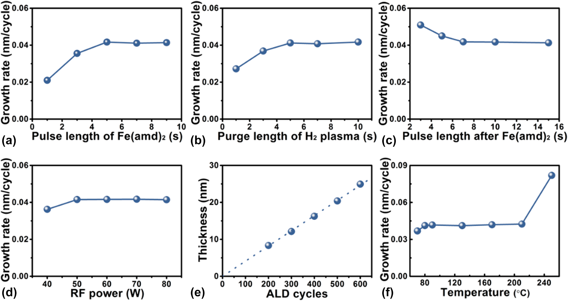
Figure 1: Dependence of the iron carbide growth rate on (a) the Fe(amd)2 pulse length, (b) H2 plasma pulse length, (c) H2 purge length following the Fe(amd)2 pulse, and (d) discharge input power. (e) Relationship between the total PEALD cycles and film thickness. (f) Influence of deposition temperature on growth rate of iron carbide.
To find out the optimal deposition temperature window for PEALD Fe1−xCx process, the effect of substrate temperature on the growth rate is investigated. Form the results shown in Fig. 1(f), Fe1−xCx films are produced by 300 PEALD cycles with standard deposition parameters except varying deposition temperature from 70 to 250 °C. Considerably different growth rates are found for the different deposition temperature regions. A constant growth rate of 0.04 nm/cycle is achieved in the deposition temperature range between 80 and 210 °C. At an elevated temperature of 250 °C, the growth rate dramatically increases to 0.08 nm/cycle, which may be due to the partial chemical vapor deposition effect by the reaction of Fe(amd)2 with molecular H2 and/or to the precursor thermal decomposition at such a high deposition temperature.
The surface morphology of the deposited 300-cycle films on the Si substrate with different deposition temperatures was examined by SEM and AFM, as shown in Fig. 2. It can be found that the deposition temperature plays a crucial role in the morphology formation of the deposited films. At low deposition temperatures of 90 and 130 °C, uniform and continuous films are formed with compact grains. When temperature is elevated to above 170 °C, discontinuous island-like films are obtained. As Moon et al. [Reference Moon, Han, Shin, Park, Kim and Kim38] pointed out, high deposition temperature is able to enhance the diffusion of species adsorbed on the substrate surface, resulting in the generation of big grains. AFM image shown in Fig. 2(f) reveals the root mean square roughness value as 0.36 nm, corresponding to 2.5% of the deposited film thickness. This roughness value confirms the formation of smooth and continuous Fe1−xCx film.

Figure 2: (a)–(e) SEM and (f) AFM images of ∼12 nm iron carbide films grown at (a) and (f) 90 °C, (b) 130 °C, (c) 170 °C, (d) 210 °C, and (e) 250 °C by 300 PEALD cycles. The scale bars stand for 100 nm.
To determine the chemical composition of Fe1−xCx film, XPS measurements were performed on samples (∼40 nm) grown on Si substrates. The samples were sputtered for 100 s with 2 kV Ar+ before XPS analysis. Figure 3 shows the survey and high-resolution XPS spectra of Fe1−xCx samples prepared at different temperatures. As shown in the survey spectra [Fig. 3(a)], only photoelectron peaks corresponding to Fe and C are observed, and the intensities of those peaks assigned to possible O and N impurities are very weak or invisible. These results indicate that Fe and C are the main elements and the deposited film are very pure. Figures 3(b)–3(e) display high-resolution XPS spectra for Fe 2p, C 1s, N 1s, and O 1s core level emissions, respectively. From the plots shown in Fig. 3(b), two main peaks are observed, which can be related to the spin orbit splitting peaks of Fe 2p at binding energies of 707.0 and 720.0 eV. These binding energy values are consistent with previous report [Reference Furlan, Jansson, Lu, Hultman and Magnuson39]. High-resolution C 1s core level spectra display a single peak centered at 283.2 eV, corresponding to the carbon in iron carbides. It should be noted that photoelectron peak (∼284.6 eV) assigned to C–C bond [Reference Kowbel and Shan40] is absent in Fig. 3(c), which means all carbon in the films exist in the Fe–C state. Regarding the N 1s and O 1s spectra shown in Figs. 3(d) and 3(e), the corresponding emission signals are very weak, indicating low contents of N and O in the films. The element composition was further calculated and summarized in Table I based on the peak areas for spectra shown in Fig. 3. For the film deposited with standard deposition parameters, the composition consists of ∼72% Fe and ∼26% C, with nitrogen and oxygen concentrations below 1%. When the deposition temperature varied from 90 to 250 °C, the ratio of iron and carbon is almost kept constant. Thus, it is concluded that the deposition temperature has minor effect on the film composition.
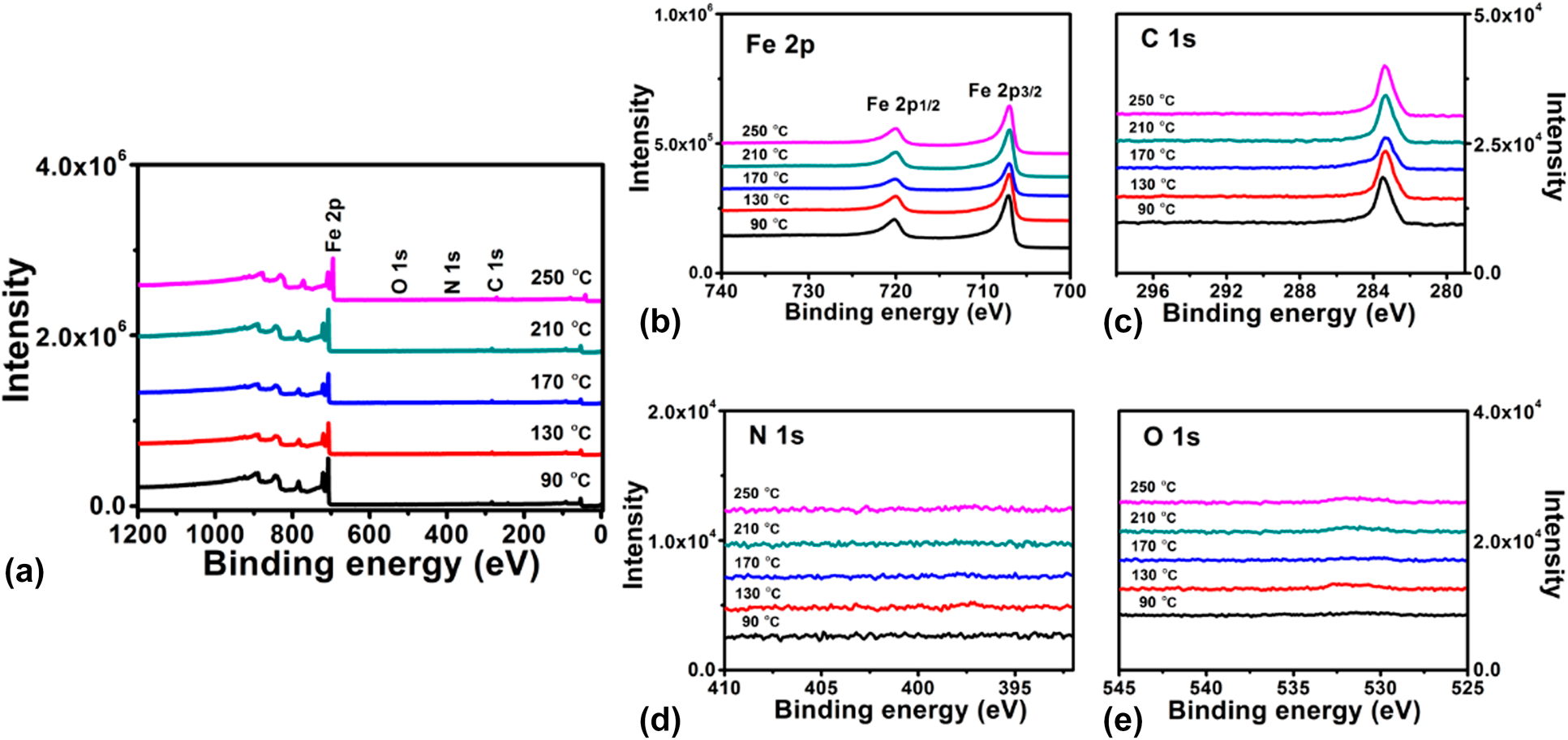
Figure 3: XPS (a) surveys for iron carbide films grown at different temperatures and high-resolution spectra of the (b) Fe 2p, (c) C 1s, (d) N 1s, and (e) O 1s core-level emissions.
TABLE I: Elemental composition of the PEALD iron carbide films grown at different temperatures.

XRD was used to determine the crystallinity of PEALD iron carbide films (∼40 nm) grown on glass slide substrates at various deposition temperatures. For the films deposited at three different temperature values of 90, 130, and 170 °C, no definite diffraction peaks [Fig. 4] can be observed, indicating that the amorphous iron carbide films were obtained. As a weak carbide material, two factors, carbon content and deposition temperature, have significant effects on the iron carbide structure. As Bauer-Grosse and Aouni [Reference Bauer-Grosse and Aouni41] pointed out, the carbon content is capable of linking the crystalline and the amorphous states in the formation of Fe1−xCx with a triode magnetron sputtering device. Jansson [Reference Jansson and Lewin10] proposed a model in which the microstructure of binary TMCs (M1−xCx) shifted from nanocomposites to amorphous materials with increasing carbon content. According to this model, there is a critical carbon amount to generate amorphous binary TMC films. As for the Fe1−xCx, this critical value is about 0.2. Besides the carbon content, the crystallinity of M1−xCx has also been affected by the deposition temperature. At low deposition temperature (250 °C), amorphous M1−xCx films tend to be formed [Reference Tajima and Hirano42]. In our case, the range of deposition temperature and the amounts of carbon in the as-deposited films are 90–130 °C and ∼25%, respectively. Thus, noncrystalline Fe1−xCx films are obtained. If the deposition temperatures are increased to higher values, such as 210 and 250 °C, and keep other deposition parameters the same, the as-deposited films exhibit polycrystalline structure, as shown in Fig. 4. The diffraction peaks centered at 40.0°, 42.6°, and 44.9° can be ascribed to (210), (102), and (211) planes of Fe7C3 crystal structure (PDF#17-0333), and this result will be identified by the following TEM analysis.
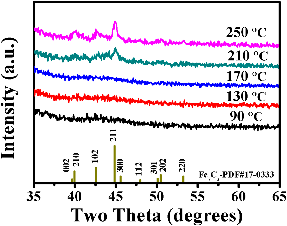
Figure 4: XRD spectra for iron carbide films grown on glass slide substrates at various temperatures.
High-resolution TEM images was further used to examine the microstructure of PEALD films (∼30 nm) grown on TEM membrane grids. Figure 5(a) shows high-resolution TEM image of Fe1−xCx film deposited at 90 °C. The absence of lattice fringes indicates noncrystallinity feature of the deposited film. In addition, no diffraction rings are observed from the corresponding electron diffraction pattern shown in Fig. 5(c), confirming again the film was entirely amorphous. Figure 5(b) represents TEM image of the films grown at 210 °C, and it can be seen that the film was polycrystalline structure. The corresponding diffraction patterns showed clear diffraction rings with indication of crystalline contribution. These results are in good agreement with the XRD measurements.
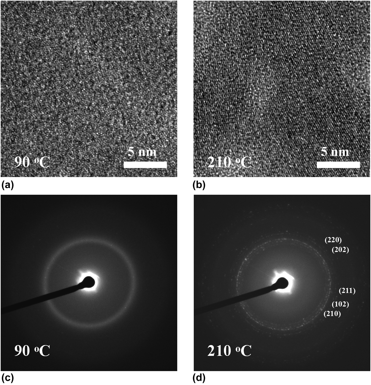
Figure 5: (a) and (c) TEM images of iron carbide films grown at 90 and 210 °C, respectively, and (b) and (d) the corresponding electron diffraction patterns.
It is well known that electrical conductivity of the TMCs is a key factor for applications in electrocatalysis and electronics. Thus, it is required to measure electrical resistivity of the as-deposited Fe1−xCx films. The dependence of the electrical resistivity on film thickness is demonstrated in Fig. 6(a). The monotonic decrease of the resistivity with increasing film thickness can be ascribed to the contributions of the electrons to scatter with grain boundaries, interfaces, and surfaces. Based on a scattering-induced model, which was given in our previous publications [Reference Guo, Li, Chen, Sang, Yang, Liu and Wang34, Reference Fan, Sang, Jiang, Yang, Zhang, Chen and Liu35], the electrical resistivity as a function of the reciprocal of the films thickness is shown in Fig. 6(b). The bulk resistivity estimated from the linear fitting was 408 µΩ cm. This value indicates that relatively conductive iron carbide film was prepared by PEALD technique.
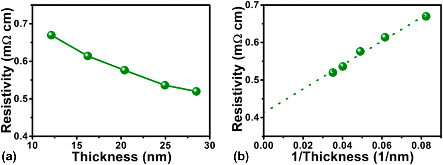
Figure 6: Dependence of the resistivity of PEALD iron carbide films grown at 90 °C on (a) the film thickness and (b) the reciprocal of the film thickness.
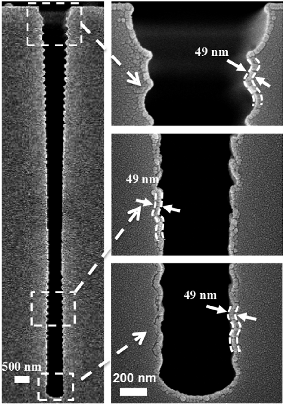
To examine the conformality of the PEALD Fe1−xCx films, a deep narrow trench with an aspect ratio of 20:1 was used as the substrate. The trench structure is about 600 nm in width and 12 μm in depth. The PEALD Fe1−xCx film was deposited on this trench structure with standard deposition parameters. From the cross-sectional SEM image shown in Fig. 7, we conclude that the trench was covered conformally by Fe1−xCx film with a uniform thickness of ∼49 nm.

Figure 7: Cross-sectional SEM image of an iron carbide film grown at 90 °C inside a trench with an aspect ratio of 20:1.
The electrocatalytic activity of the PEALD Fe1−xCx film grown on CC was evaluated for the HER. LSV measurements were carried out in a N2 saturated 1 M KOH electrolyte over the voltage scan range from 0 to −0.6 V versus reversible hydrogen electrode at a scan rate of 5 mV/s. Figure 8(a) displays the resultant LSV curves with proper iR-correction. Fe1−xCx film has a relatively small overpotential of 117 mV at 10 mA/cm2. The Tafel equation relates the potential to the current density as follows: η = b log j + a, where η is the overpotential, j is the current density, and b is the Tafel slope. Based on the Tafel curve shown in Fig. 8(b), a Tafel slope of 121 mV/dec is obtained. The stability of the PEALD Fe1−xCx/CC was determined by the comparison of LSV curves obtained before and after 5000-cycle cyclic voltammetry (CV) measurements, as displayed in Fig. 8(c). It can be found that no appreciable difference between the two curves, demonstrating an excellent stability of the deposited Fe1−xCx/CC.

Figure 8: (a) LSV curves and (b) Tafel plots of the PEALD Fe1−xCx/carbon cloth and state-of-art Pt/C catalysts. LSV curve of bare carbon cloth is also included for comparison. (c) Comparison of LSV curves for PEALD Fe1−xCx/carbon cloth before and after 5000 cycles cyclic voltammetry.
Conclusions
A new PEALD process is developed for the fabrication of Fe1−xCx thin films using bis(N,N′-di-tert-butylacetamidinato)iron(II) as a precursor and H2 plasma as a reactant. At a certain condition [5 s pulse of Fe(amd)2, 10 s pulse of H2 gas, 10 s pulse for H2 plasma, 10 s pulse of H2 gas, 60 W input power, and 90 °C deposition temperature], the process shows an ideal self-limiting PEALD fashion at a saturated film growth rate of 0.04 nm/cycle. Based on XPS analysis, the film composition is determined to be about Fe0.74C0.26 for the wide PEALD temperature window of 80–210 °C. Both TEM and XRD results demonstrate that the deposited Fe1−xCx films are amorphous structures at the deposition temperature range of 80–170 °C, while crystal structure is formed when the temperature is elevated to 210 °C. The electrical resistivity of Fe1−xCx films is 408 mΩ cm, which was suitable for the electrocatalysis application. A uniform iron carbide film is grown inside the trench with an aspect ratio of 20:1, indicating the ideal step coverage of the PEALD films. Finally, the PEALD Fe1−xCx/CC is applied for hydrogen evolution and exhibits excellent electrocatalytic performance.
Acknowledgments
This work was financially supported by the National Natural Science Foundation of China (Grant Nos. 11775028 and 11875090), Collaborative Innovation Center of Green Printing & Publishing Technology (Grant No. 15208), and Beijing Institute of Graphic Communication Project (Grant Nos. Ea201801, KM201810015009, and KM201810015005).


