


1 Introduction
Since its commissioning in 2008, the Petawatt High-Energy Laser for Heavy-Ion Experiments (PHELIX) facility at GSI (GSI Helmholtzzentrum für Schwerionenforschung GmbH, Darmstadt, Germany)[ Reference Bagnoud, Aurand, Blazevic, Borneis, Bruske, Ecker, Eisenbarth, Fils, Frank, Gaul, Goette, Haefner, Hahn, Harres, Heuck, Hochhaus, Hoffmann, Javorkova, Kluge, Kuehl, Kunzer, Kreutz, Merz-Mantwill, Neumayer, Onkels, Reemts, Rosmej, Roth, Stoehlker, Tauschwitz, Zielbauer, Zimmer and Witte1], has been a unique infrastructure for high-energy-density (HED) physics research, thanks to its combined operation with the heavy-ion beam from the linear accelerator (UNILAC) of GSI. Here, different aspects of matter at extreme conditions have been studied using pump–probe setups. As an example, the probing of laser-generated plasmas by ion bunches of the accelerator has given crucial new experimental insight on the ion stopping power to discriminate between theoretical descriptions of matter in extreme conditions relevant to inertial-confinement-fusion research[ Reference Frank, Blazevic, Bagnoud, Basko, Boerner, Cayzac, Kraus, Hessling, Hoffmann, Ortner, Otten, Pelka, Pepler, Schumacher, Tauschwitz and Roth2, Reference Cayzac, Frank, Ortner, Bagnoud, Basko, Bedacht, Blaeser, Blazevic, Busold, Deppert, Ding, Ehret, Fiala, Frydrych, Gericke, Hallo, Helfrich, Jahn, Kjartansson, Knetsch, Kraus, Malka, Neumann, Pepitone, Pepler, Sander, Schaumann, Schlegel, Schroeter, Schumacher, Seibert, Tauschwitz, Vorberger, Wagner, Weih, Zobus and Roth3]. PHELIX on its own has also been instrumental in advancing the understanding of high-intensity laser–matter interaction on the one hand, as well as the properties of warm dense matter (WDM), which can be found in the interior of many astrophysical objects, on the other. Examples here include significant contributions to the field of laser-driven secondary sources, in particular to ion acceleration. Here, in the quest for the highest achievable proton energies, PHELIX held the world record for some time[ Reference Wagner, Deppert, Brabetz, Fiala, Kleinschmidt, Poth, Schanz, Tebartz, Zielbauer, Roth, Stoehlker and Bagnoud4]. The vicinity of the GSI heavy-ion accelerator infrastructure also leads to investigations of laser-driven ion sources in the context of accelerator facilities[ Reference Busold, Almomani, Bagnoud, Barth, Bedacht, Blazevic, Boine-Frankenheim, Brabetz, Burris-Mog, Cowan, Deppert, Droba, Eickhoff, Eisenbarth, Harres, Hoffmeister, Hofmann, Jaeckel, Jaeger, Joost, Kraft, Kroll, Kaluza, Kester, Lecz, Merz, Nuernberg, Al-Omari, Orzhekhovskaya, Paulus, Polz, Ratzinger, Roth, Schaumann, Schmidt, Schramm, Schreiber, Schumacher, Stoehlker, Tauschwitz, Vinzenz, Wagner, Yaramyshev and Zielbauer5].
The versatile architecture of the PHELIX system allows for vastly diverse operation parameters and therefore the investigation of a large range for physical phenomena. In its short-pulse mode, PHELIX delivers sub-ps pulses with up to 200 J of pulse energy. Depending on the focusing geometry, intensities from ${10}^{19}$
up to
${10}^{19}$
up to ${10}^{21}\ \mathrm{W}/{\mathrm{cm}}^2$
can be reached. PHELIX can also be operated in its long-pulse mode, delivering pulses with a duration that can be varied in the few nanosecond range and maximum energies of 200–300 J at the second harmonic. Since PHELIX is based on Nd:glass technology, currently without active cooling, the shot rate is limited to one shot every 90 min.
${10}^{21}\ \mathrm{W}/{\mathrm{cm}}^2$
can be reached. PHELIX can also be operated in its long-pulse mode, delivering pulses with a duration that can be varied in the few nanosecond range and maximum energies of 200–300 J at the second harmonic. Since PHELIX is based on Nd:glass technology, currently without active cooling, the shot rate is limited to one shot every 90 min.
As previously shown[ Reference Zimmer, Scheuren, Ebert, Schaumann, Rodel, Roth, Schmitz, Bagnoud and Hornung6], pulses from PHELIX in the short-pulse mode are especially suited for the acceleration of protons to high energies by the favourable scaling of the combination of high pulse energy and tight focusing. In addition to the laser parameters, controlling the plasma conditions prior to the impact of the main laser pulse has a strong influence on laser absorption and the results achieved in ion-acceleration experiments[ Reference Hornung, Zobus, Boller, Brabetz, Eisenbarth, Kuehl, Major, Ohland, Zepf, Zielbauer and Bagnoud7]. This control is mainly governed by the temporal contrast of the laser pulse, which has been at the centre of investigations at PHELIX over the past years. The continuous contrast improvement has been the driver for the evolution in the laser architecture, particularly in the frontend area of PHELIX[ Reference Bagnoud and Wagner8– Reference Wagner, Hornung, Schmidt, Eckhardt, Roth, Stoehlker and Bagnoud11].
The situation for electron acceleration is fundamentally different. Although the PHELIX parameters are not optimal for accelerating electrons in the laser-wakefield-acceleration scheme, efficient electron acceleration can be realized in the direct laser acceleration regime[ Reference Rosmej, Gyrdymov, Guenther, Andreev, Tavana, Neumayer, Zaehter, Zahn, Popov, Borisenko, Kantsyrev, Skobliakov, Panyushkin, Bogdanov, Consoli, Shen and Pukhov12]. Here, a near-critical density target is used to accelerate electron bunches with a high charge to moderate energies reaching a maximum of 100 MeV with a thermal distribution, corresponding to an electron temperature around 10 MeV. In order to generate plasma conditions matched to the high-intensity drive-laser pulse, an additional, controlled ns-prepulse is necessary in combination with a foam target. The PHELIX architecture conveniently allows for the generation of such a ns-prepulse with a high level of control over its parameters in energy and temporal pulse shape, in addition to the high-intensity sub-picosecond driver pulse. Such combined operation of the short- and long-pulse modes requires the synchronization between the two frontends for a controlled variable delay between the two pulses, which has also been realized in routine operation.
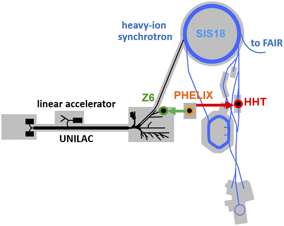
Figure 1 The location of the PHELIX building on the GSI campus allows for using both high-energy laser pulses and the heavy-ion beam in combination at the Z6 experimental area downstream of the linear accelerator section, the UNILAC and at HHT, downstream of the heavy-ion synchrotron SIS18.
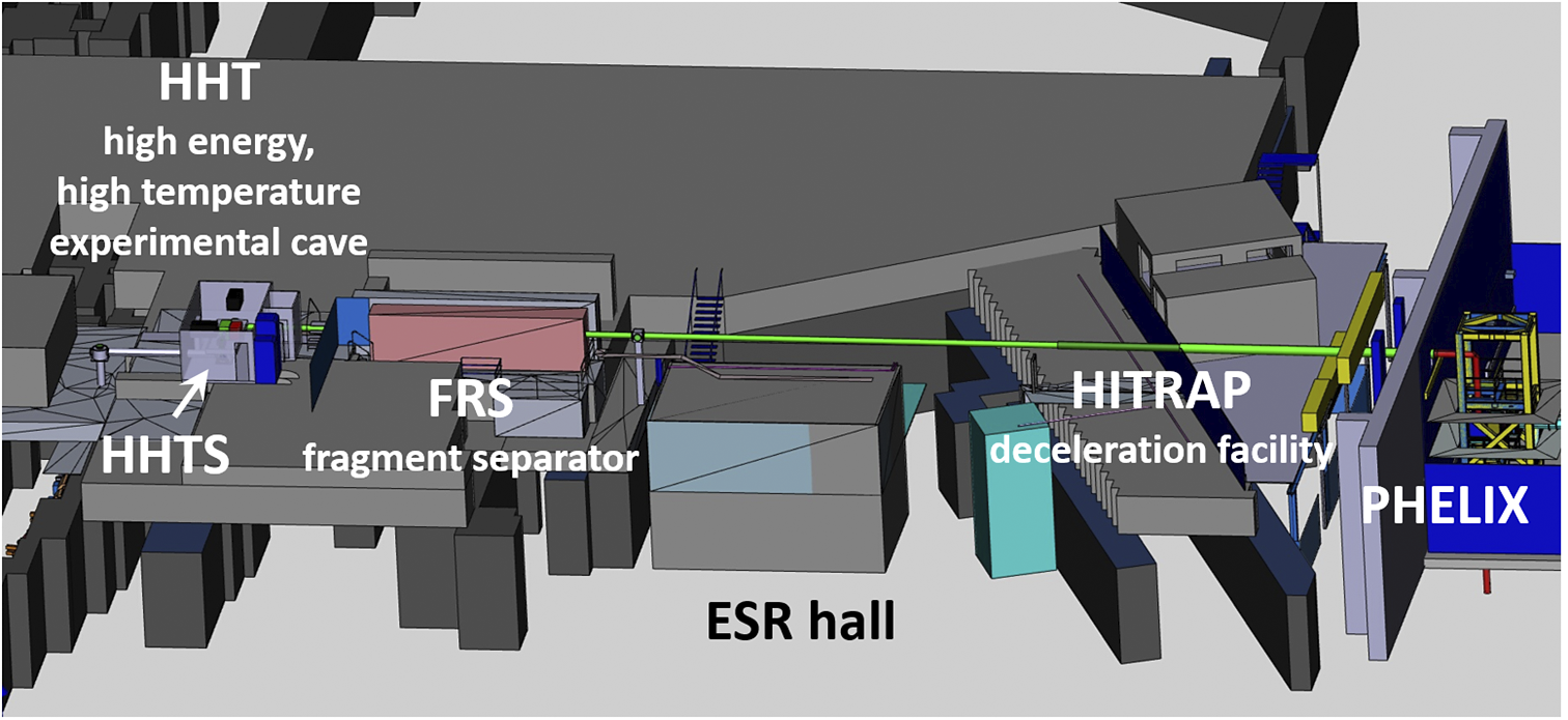
Figure 2 Digital mock-up of the experimental hall (ESR hall) downstream of the SIS18 heavy-ion synchrotron, showing the PHELIX beamline (green/grey tube) as it traverses several experimental areas on its way to HHT. The total length of the beam transport is of the order of 65 m.
Using PHELIX pulses to generate X-rays can be done both in the short- and long-pulse modes. With the relativistic intensities of the short pulse of PHELIX, X-ray photon energies in the range of 20–200 keV with a conversion efficiency of the order of ${10}^{-4}$
have been achieved[
Reference Borm, Khaghani and Neumayer13], which can serve as a backlighter source for, e.g., X-ray radiography on samples with high areal density, typical for experiments involving WDM[
Reference Morace, Fedeli, Batani, Baton, Beg, Hulin, Jarrott, Margarit, Nakai, Nakatsutsumi, Nicolai, Piovella, Wei, Vaisseau, Volpe and Santos14,
Reference Ceurvorst, Theobald, Rosenberg, Radha, Stoeckl, Betti, Anderson, Marozas, Goncharov, Campbell, Shuldberg, Luo, Sweet, Aghaian, Carlson, Bachmann, Döppner, Hohenberger, Glize, Scott, Colaitis and Regan15]. When using the PHELIX ns-pulse, the conversion efficiency is similar, albeit at lower X-ray photon energies (a few keV to a few tens of keV). Nevertheless, these sources are also well-suited for investigating the microscopic structure of dense plasmas by, e.g., X-ray diffraction (XRD) or X-ray Thomson scattering (XRTS)[
Reference Barrios, Fournier, Regan, Landen, May, Opachich, Widmann, Bradley and Collins16,
Reference Rygg, Smith, Lazicki, Braun, Fratanduono, Kraus, McNaney, Swift, Wehrenberg, Coppari, Ahmed, Barrios, Blobaum, Collins, Cook, Di Nicola, Dzenitis, Gonzales, Heidl, Hohenberger, House, Izumi, Kalantar, Khan, Kohut, Kumar, Masters, Polsin, Regan, Smith, Vignes, Wall, Ward, Wark, Zobrist, Arsenlis and Eggert17]. For such experiments, the laser-driven backlighter again has to be synchronized with the generation of the plasma state to be investigated, similar to the case of the direct laser acceleration scheme of electrons mentioned above. However, the vicinity of PHELIX to GSI’s heavy-ion accelerator infrastructure makes it stand out from other high-intensity, high-energy laser systems, owing to the possibility of combining the heavy-ion bunches with high-energy laser pulses. The temporal synchronization between the PHELIX pulses and the ion bunches is a mandatory requirement for such experiments, further driving the system development.
${10}^{-4}$
have been achieved[
Reference Borm, Khaghani and Neumayer13], which can serve as a backlighter source for, e.g., X-ray radiography on samples with high areal density, typical for experiments involving WDM[
Reference Morace, Fedeli, Batani, Baton, Beg, Hulin, Jarrott, Margarit, Nakai, Nakatsutsumi, Nicolai, Piovella, Wei, Vaisseau, Volpe and Santos14,
Reference Ceurvorst, Theobald, Rosenberg, Radha, Stoeckl, Betti, Anderson, Marozas, Goncharov, Campbell, Shuldberg, Luo, Sweet, Aghaian, Carlson, Bachmann, Döppner, Hohenberger, Glize, Scott, Colaitis and Regan15]. When using the PHELIX ns-pulse, the conversion efficiency is similar, albeit at lower X-ray photon energies (a few keV to a few tens of keV). Nevertheless, these sources are also well-suited for investigating the microscopic structure of dense plasmas by, e.g., X-ray diffraction (XRD) or X-ray Thomson scattering (XRTS)[
Reference Barrios, Fournier, Regan, Landen, May, Opachich, Widmann, Bradley and Collins16,
Reference Rygg, Smith, Lazicki, Braun, Fratanduono, Kraus, McNaney, Swift, Wehrenberg, Coppari, Ahmed, Barrios, Blobaum, Collins, Cook, Di Nicola, Dzenitis, Gonzales, Heidl, Hohenberger, House, Izumi, Kalantar, Khan, Kohut, Kumar, Masters, Polsin, Regan, Smith, Vignes, Wall, Ward, Wark, Zobrist, Arsenlis and Eggert17]. For such experiments, the laser-driven backlighter again has to be synchronized with the generation of the plasma state to be investigated, similar to the case of the direct laser acceleration scheme of electrons mentioned above. However, the vicinity of PHELIX to GSI’s heavy-ion accelerator infrastructure makes it stand out from other high-intensity, high-energy laser systems, owing to the possibility of combining the heavy-ion bunches with high-energy laser pulses. The temporal synchronization between the PHELIX pulses and the ion bunches is a mandatory requirement for such experiments, further driving the system development.
GSI’s heavy-ion accelerator is a unique facility with the future prospect of the Facility for Antiproton and Ion Research (FAIR) currently under construction[ 18]. Using the heavy-ion beam for heating holds promise to reach WDM conditions over large volumes on a long timescale compared to short-pulse laser drivers, and can therefore be assumed to be in local thermal equilibrium. The investigation of matter under such conditions represents one of the main goals in plasma physics of the FAIR research programme[ Reference Schoenberg, Bagnoud, Blazevic, Fortov, Gericke, Golubev, Hoffmann, Kraus, Lomonosov, Mintsev, Neff, Neumayer, Piriz, Redmer, Rosmej, Roth, Schenkel, Sharkov, Tahir, Varentsov and Zhao19]. In order to exploit the combined availability of the heavy-ion accelerator and the PHELIX high-energy laser pulse, we have recently commissioned a beamline transporting the PHELIX ns-pulse to the HHT (high energy, high temperature) experimental area, which is served by the ion bunches from the heavy-ion synchrotron SIS18. Figure 1 schematically shows the location of PHELIX with respect to the accelerator infrastructure of GSI, indicating the Z6 experimental area, where the PHELIX pulse can be used in combination with the heavy ions from UNILAC, as well as the beamline to HHT, which allows for the combination with the heavy ions from SIS18. A more detailed perspective of this new part of the infrastructure is provided in Figure 2, showing a digital mock-up of the accelerator experiment hall, which needs to be traversed to reach the HHT cave from the PHELIX building. This new capability allows for novel experimental schemes to be tested, but is currently limited by the large discrepancy between the repetition rates of PHELIX at one full-energy shot per 90 min, and that of the accelerator, which could be as high as one ion bunch every few seconds. In order to make full use of the available infrastructure, increasing the PHELIX repetition rate constitutes one of the main ongoing laser-development directions.
The laser system and its commissioning were described in detail by Bagnoud et al. [ Reference Bagnoud, Aurand, Blazevic, Borneis, Bruske, Ecker, Eisenbarth, Fils, Frank, Gaul, Goette, Haefner, Hahn, Harres, Heuck, Hochhaus, Hoffmann, Javorkova, Kluge, Kuehl, Kunzer, Kreutz, Merz-Mantwill, Neumayer, Onkels, Reemts, Rosmej, Roth, Stoehlker, Tauschwitz, Zielbauer, Zimmer and Witte1]. However, during the years of user operation since, numerous aspects of PHELIX have been further developed, based on user feedback and the incorporation of technological advances. Owing to this process of constant improvement and development, the PHELIX performance available to users at present significantly differs from that at the time of commissioning. Therefore, in this paper we summarize the current facility performance, allowing for putting recent results of experiments at PHELIX into better perspective. In addition, the techniques and choices made for the performance improvement presented here have been extensively tested in daily operation conditions, which could be of interest for other laser facilities.
This paper first reviews the present status of the PHELIX facility with the emphasis on the most important developments and improvements, which include the frontend architecture for temporal-contrast control, temporal-contrast metrology with a high dynamic range, wavefront metrology and control, both in the laser chain and after the grating compressor. The subsequent section describes the newly implemented beam transport, with an emphasis on the frequency doubling. It details the application of the PHELIX pulses in combined heavy-ion high-energy laser experiments and also the technical solution of their synchronization to the ion bunch from SIS18, which is a prerequisite.
2 PHELIX – current status
Figure 3 shows a detailed layout of the PHELIX system. The femtosecond frontend (fsFE) generates the pulse for the short-pulse (sub-ps) mode of operation. Compared to the original frontend used for the commissioning of the laser in 2008, the frontend has undergone several upgrades and redesigns with the goal to improve the temporal-contrast performance of PHELIX and maintain it at the cutting edge of technology. Currently, it consists of a commercial femtosecond Ti:sapphire laser oscillator (Mira Optima 900F, Coherent Corp.) pumped by a continuous wave laser (Millennia, Spectra Physics). The central wavelength is strongly detuned with respect to the peak of the Ti:sapphire emission cross-section to 1053 nm in order to match the gain maximum of the amplifier further along the laser chain using Nd-doped phosphate glass (Nd:glass) as the gain medium. The oscillator repetition rate is tuned to 72 MHz, a sub-harmonic of the 108 MHz clock of GSI’s UNILAC, using a Synchrolock (Coherent Corp.) to lock to this frequency. For temporal-contrast management, the first amplifier is a two-stage short-pulse-pumped ultrafast optical parametric amplifier (uOPA) (cf. Section 2.2), followed by the pulse stretcher, an acousto-optic programmable dispersive filter (DAZZLER, Fastlite) for dispersion control and a regenerative amplifier in the ring geometry based on Ti:sapphire as the active medium. This part, operating at 10 Hz repetition rate, delivers an output pulse energy of up to 20 mJ in an approximately 9 nm FWHM (full width at half maximum) wide spectrum centred at 1053 nm, that can support a transform-limited pulse duration of the order of 200 fs. Depending on the application, this pulse can be split into two replicas with a variable delay between them.
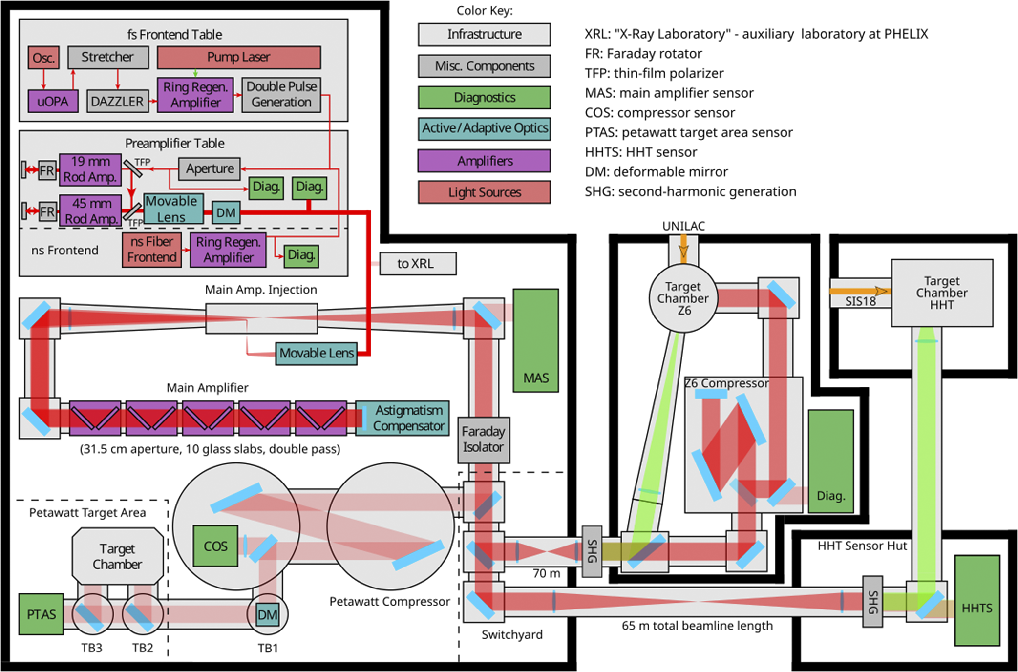
Figure 3 Schematic floor plan of PHELIX. The laser amplifier chain is situated in the PHELIX laser bay, together with the grating compressor and the petawatt target area (PTA) for the short, highest-intensity pulses. The PHELIX long pulse can be directed to the Z6 and HHT experiment areas, where it can be combined with the heavy-ion beams from UNILAC and SIS18, respectively. In addition, the Z6 area has the possibility to use the sub-aperture, short-pulse beam of PHELIX. This figure is based on the original version by Ohland[ Reference Ohland20] and its modification by Malki[ Reference Malki21].
In the long-pulse mode, the nanosecond frontend (nsFE), based on our own development, provides the first pulses for the laser chain. It is built out of commercial off-the-shelf components and consists of a first module including a fiber-based oscillator and a subsequent acousto-optic modulator, a fiber amplifier and an optical gate, which allows for the generation of a large variety of temporal pulse shapes with a duration between 0.3 and 10 ns at 1053 nm wavelength (Modbox, iXblue). Using a programmable arbitrary-waveform generator (AWG-100D, Kentech Instruments Ltd.), the temporal pulse shape can be precisely tailored to the particular needs of an experiment, which, with a bin width of 125 ps and a bandwidth of 8 GHz, supports a shortest rising edge of 125 ps. This module is followed by a Nd:glass-based regenerative amplifier operated at 0.5 Hz to a level of 10–20 mJ, depending on the pulse shape.
The subsequent amplifier stage is the preamplifier (PA) using Nd:glass in the rod geometry for further amplifying the stretched sub-ps or the ns-pulses, or both, as schematically shown in Figure 3. The current PA replaces the original one to enable working at higher repetition rates down to 1 shot per 30 s (cf. Section 2.1). It now consists of two flashlamp-pumped, in-house-built amplifier heads with rod diameters of 19 and 45 mm, respectively. The amplifier heads are double-passed to facilitate thermal management. They are separated by Kepler telescopes, equipped with spatial filters at the focus positions, Pockels cells for optical isolation and Faraday rotators (FRs) for the compensation of thermally induced birefringence. The Pockels cells and the FRs have apertures of 20 and 50 mm at the two amplifier stages, respectively. Amplification in the PA results in pulse energies of up to 20 J (large aperture, 10 ns pulse length) and can be operated at a constant repetition rate of up to once every 30 s, although standard operation limits the shot rate to once every 2 min.
Following the PA, the main amplifier (MA) contains five flashlamp-pumped Nd:glass amplifier modules in the slab geometry used in double-pass configuration, with a 315-mm clear aperture and a maximum gain of 100, whereas the daily operation point of the laser uses a gain between 50 and 65. The available energy is limited by the damage threshold of optics downstream of the amplifier. For ns-pulses, the amplifier output can reach 300 J with pulses of 1 ns duration, and the maximum possible energy scales with the square root of the pulse duration up to about 1 kJ for 10 ns square pulses. Note that frequency doubling to 527 nm is systematically done for nanosecond pulses in order to increase laser–plasma coupling and also to reach higher shock pressures, which in addition also serves as a measure to protect the system from back-reflected light. For short pulses, the nominal amplifier output energy is limited to 250 J, due to the damage threshold of the compressor gratings, where the peak fluence is kept below $0.85\ \mathrm{J}/{\mathrm{cm}}^2$
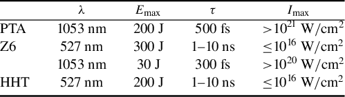
. The laser-pulse parameters of the PHELIX operation point are below the maximum nominal values stated above and are summarized in Table 1. In daily routine operation, these are the characteristics (in particular the energy) that are available on the target after passing through the respective beamlines that can be selected by using the appropriate mirrors at the switchyard after the amplifier and Faraday isolator. The experimental areas include the petawatt target area (PTA), where the high-intensity short-pulse and long-pulse options can be used in combination, typically with the ns-pulse as a prepulse, with an energy at the percent level of that of the main sub-ps pulse. At the Z6 area the high-energy long-pulse mode is available at the second harmonic, or alternatively, the sub-aperture, short-pulse beam of PHELIX at
$0.85\ \mathrm{J}/{\mathrm{cm}}^2$
. The laser-pulse parameters of the PHELIX operation point are below the maximum nominal values stated above and are summarized in Table 1. In daily routine operation, these are the characteristics (in particular the energy) that are available on the target after passing through the respective beamlines that can be selected by using the appropriate mirrors at the switchyard after the amplifier and Faraday isolator. The experimental areas include the petawatt target area (PTA), where the high-intensity short-pulse and long-pulse options can be used in combination, typically with the ns-pulse as a prepulse, with an energy at the percent level of that of the main sub-ps pulse. At the Z6 area the high-energy long-pulse mode is available at the second harmonic, or alternatively, the sub-aperture, short-pulse beam of PHELIX at $1\omega$
can be used here. At HHT, the PHELIX ns-pulse is available at the second harmonic, with up to 200 J of energy.
$1\omega$
can be used here. At HHT, the PHELIX ns-pulse is available at the second harmonic, with up to 200 J of energy.
Table 1 PHELIX pulse parameters at the different experimental areas (central wavelength $\lambda$
, maximum pulse energy
$\lambda$
, maximum pulse energy ${E}_{\mathrm{max}}$
, pulse duration
${E}_{\mathrm{max}}$
, pulse duration $\tau$
and resulting maximum intensity
$\tau$
and resulting maximum intensity ${I}_{\mathrm{max}}$
). Laser pulses with these characteristics are available on target during routine operation and are somewhat lower than the maximum possible output of the system in order to allow for long-term, damage-free operation.
${I}_{\mathrm{max}}$
). Laser pulses with these characteristics are available on target during routine operation and are somewhat lower than the maximum possible output of the system in order to allow for long-term, damage-free operation.
Active wavefront control, which was not offered in routine operation at the time of the commissioning of the laser, has been implemented step by step at PHELIX and it is now part of the standard operation features and procedures (cf. Section 2.3). The combination of a 65-mm-diameter deformable mirror (DM) located at the PA output, adjustable telescopes and bending of a 400-mm-diameter mirror in the MA path enables controlling static and on-shot aberrations. In addition, a dedicated full-aperture DM located after the PTA compressor is being newly implemented for additional control of the final focusing.
While the basic architecture of PHELIX is unchanged compared to the system originally commissioned[ Reference Bagnoud, Aurand, Blazevic, Borneis, Bruske, Ecker, Eisenbarth, Fils, Frank, Gaul, Goette, Haefner, Hahn, Harres, Heuck, Hochhaus, Hoffmann, Javorkova, Kluge, Kuehl, Kunzer, Kreutz, Merz-Mantwill, Neumayer, Onkels, Reemts, Rosmej, Roth, Stoehlker, Tauschwitz, Zielbauer, Zimmer and Witte1], a number of improvements have been implemented in the past years in order to optimize the available pulse characteristics for the respective applications as outlined above. In the following sections, we will review these developments in more detail.
2.1 Preamplifier upgrade
Originally, the PHELIX PA consisted of two 19-mm and one 45-mm-diameter flashlamp-pumped Nd:glass amplifiers used in single-pass configuration, designed to work at one shot every 10 min. A growing demand from the experimental side was the increase of the repetition rate of this system in order to deliver medium-energy pulses of up to 20 J with repetition rates of one shot per minute or higher. The main cause limiting the shot rate in the PA is the necessary cool-down time to avoid the pile-up of thermal distortion effects in the wavefront and amplitude. For a system such as PHELIX, the main effects are stress-induced birefringence and focus degradation by thermal effects.
A new design of the optical setup, which is using one 19-mm-diameter and one 45-mm-diameter amplifier head, both operated in a double-pass configuration, has been implemented (Figure 3), reducing the impact of the limiting effects, thereby increasing the possible repetition rate. In addition, new power supplies with a shot cycle up to once every 15–20 s and a new shot sequencer have been developed. This new setup also increases the total gain in order to reach up to 20 J output energy for 10 ns pulses. Furthermore, the double-pass setup, as depicted in Figure 3, allows for the intrinsic compensation of birefringence effects using an FR in the beam path. The incoming p-polarized beam passes a thin-film polarizer (TFP) and the amplifier. The following FR turns the polarization by 45°. The reflected beam passes the rotator, again rotating it by another 45°. After propagating through the amplifier, the now s-polarized beam is reflected at the TFP. Due to the FR being a symmetry-breaking element, any depolarization, including local stress-induced depolarization during the first amplifier pass, is compensated in the second pass. As a result, no amplitude distortion is visible at the PA output for shot rates up to around one shot every 20 s. However, at this shot rate the system does not have sufficient time to cool down between shots and therefore thermal effects accumulate and, since the birefringence is compensated due to the double-pass setup, lead to increased thermal lensing. It turns out that this pile-up of thermal-lensing effects converges towards a dynamic equilibrium after a certain number of shots when operated at a constant shot rate. This equilibrium is determined by the temperature-dependent cooling rate and the heat that is injected during each shot, which, with an automatic shot sequencer developed for this purpose, was kept constant over time. Figure 4 depicts the peak-to-valley values of the output wavefront after the 45 mm amplifier over time at a rate of one shot every 45 s. The equilibrium state is reached after a warm-up time of about 20 min. The peak-to-valley wavefront distortion of about 2 $\lambda$
mostly consists of defocus aberrations. These aberrations can easily be compensated by moving a lens in the Kepler telescopes present in the setup, which is also shown in Figure 4. Remaining higher-order aberrations are compensated with adaptive optics. In the default mode of routine operation, the shot rate is reduced to allow for the system to mostly cool down between shots. At one shot every 2 min the wavefront or amplitude distortions induced by the thermal effects are already small, in particular when compared to those introduced by the MA on a full-energy shot. This time interval was therefore chosen as the minimum between consecutive shots in ‘shot-on-demand’ operation of the PA.
$\lambda$
mostly consists of defocus aberrations. These aberrations can easily be compensated by moving a lens in the Kepler telescopes present in the setup, which is also shown in Figure 4. Remaining higher-order aberrations are compensated with adaptive optics. In the default mode of routine operation, the shot rate is reduced to allow for the system to mostly cool down between shots. At one shot every 2 min the wavefront or amplitude distortions induced by the thermal effects are already small, in particular when compared to those introduced by the MA on a full-energy shot. This time interval was therefore chosen as the minimum between consecutive shots in ‘shot-on-demand’ operation of the PA.
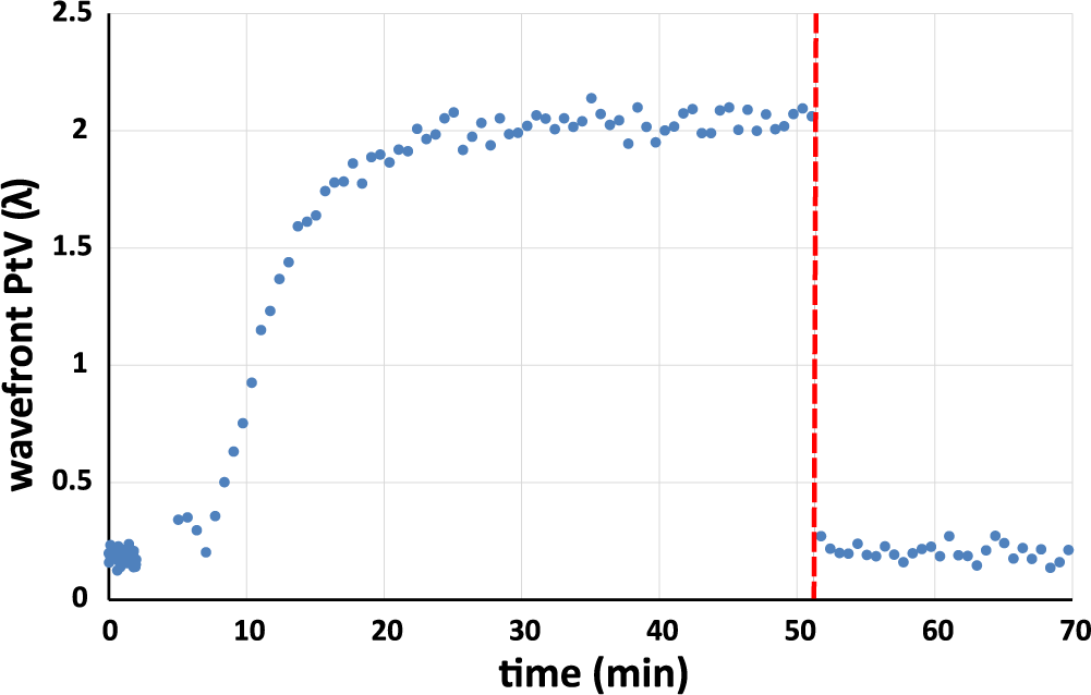
Figure 4 Build-up of wavefront aberrations in high-repetition-rate operation of the preamplifier. The peak-to-valley value of the wavefront distribution as a function of time is shown after the 45-mm preamplifier module with 45 s between laser shots, starting at 6 min. After about 20 min an equilibrium is reached, in which the aberrations remain constant over time. At 51 min (red dashed line) the aberrations, which mostly consist of defocus, are compensated by moving a lens in the Kepler telescope of the preamplifier setup.
In conclusion, the new PA is capable of amplifying near diffraction-limited beams up to a shot rate of about one shot per 30 s. Higher shot rates could be reached at the expense of wavefront distortions and are only limited by the thermal fracture of the 45-mm rod for shot rates estimated between 0.1 and 1 Hz.
2.2 Temporal-contrast improvement and control
The initial architecture at PHELIX featured a classic chirped-pulse amplifier (CPA)[
Reference Strickland and Mourou22] that did not include any specific temporal-contrast-enhancement modules. However, because of the combined increase in focused intensities and requirements from users, the temporal contrast of the laser pulses has become an increasingly crucial feature. Considerable effort has been invested in this topic worldwide[
Reference Dorrer, Begishev, Okishev and Zuegel23–
Reference Kiriyama, Miyasaka, Kon, Nishiuchi, Sagisaka, Sasao, Pirozhkov, Fukuda, Ogura, Kondo, Nakanii, Mashiba, Dover, Chang, Kando, Bock, Ziegler, Pueschel, Schlenvoigt, Zeil and Schramm25] and also at PHELIX, in order to improve the leading edge of the pulse with an emphasis on the reduction of the amplified spontaneous emission (ASE) plateau and elimination of unwanted prepulses. The improvement and control of the temporal contrast have been made possible by the implementation of a short-pulse-pumped uOPA stage in the frontend[
Reference Bagnoud and Wagner8,
Reference Wagner, Joao, Fils, Gottschall, Hein, Koerner, Limpert, Roth, Stoehlker and Bagnoud26], which, by using the instantaneous nonlinear optical effect of parametric amplification, intrinsically provides an excellent temporal contrast outside the window of the ps-timescale pump pulse. The experience gathered with this system motivated the development of a more energetic version in a two-stage configuration, delivering pulses up to the mJ energy range, which is now in operation[
Reference Zobus, Brabetz, Zou and Bagnoud27–
Reference Zobus, Brabetz, Hornung, Ohland, Reemts, Zou, Loeser, Albach, Schramm and Bagnoud29]. This allowed us to omit the linear regenerative amplifier stage that was previously in operation at the fsFE and was the origin of a number of prominent prepulses in the temporal shape. As a result, PHELIX now routinely delivers pulses with a typical temporal shape corresponding to the third-order cross-correlation trace shown in Figure 5. These measurements are performed after the fsFE and therefore not at full energy. However, owing to the low B-integral of the final passes in the MA, we expect no significant changes to the shape of the curve at full energy[
Reference Zobus30]. Here, the ASE level on the ns-timescale is below ${10}^{-12}$
with respect to the main pulse. We can see a series of prepulses, a number of which are measurement artifacts (cf. Schanz et al. [
Reference Schanz, Brabetz, Posor, Reemts, Roth and Bagnoud31]), and the rest are sufficiently low in order not to be destructive. The remaining rising slope leading to the main pulse is clearly resolved and not masked by the limitations of the measurement tools. Its origin has recently been shown to lie in the combination of beam size and surface imperfection of the stretcher setup necessary for the CPA scheme, and its mitigation and control are still being further investigated[
Reference Schanz, Roth and Bagnoud32–
Reference Roeder, Zobus, Major and Bagnoud34].
${10}^{-12}$
with respect to the main pulse. We can see a series of prepulses, a number of which are measurement artifacts (cf. Schanz et al. [
Reference Schanz, Brabetz, Posor, Reemts, Roth and Bagnoud31]), and the rest are sufficiently low in order not to be destructive. The remaining rising slope leading to the main pulse is clearly resolved and not masked by the limitations of the measurement tools. Its origin has recently been shown to lie in the combination of beam size and surface imperfection of the stretcher setup necessary for the CPA scheme, and its mitigation and control are still being further investigated[
Reference Schanz, Roth and Bagnoud32–
Reference Roeder, Zobus, Major and Bagnoud34].
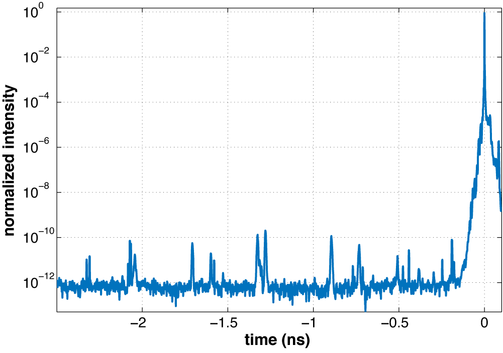
Figure 5 Typical temporal pulse shape of the compressed PHELIX sub-ps pulse, measured with a high-dynamic-range third-order cross-correlator. On top of a very low ASE background limited by the noise of the measurement device, the peaks before the main pulse are mainly due to artifacts[ Reference Zobus30, Reference Schanz, Brabetz, Posor, Reemts, Roth and Bagnoud31].
The development in temporal contrast also required an improved metrology that would allow for the quantitative verification of the results. Also developed at PHELIX[
Reference Schanz, Brabetz, Posor, Reemts, Roth and Bagnoud31,
Reference Schanz, Wagner, Roth and Bagnoud35,
Reference Schanz, Wagner, Bagnoud and Roth36], a specially designed third-order cross-correlator was built (EICHEL) with the detectable contrast ratio increased to the level of ${10}^{13}$
in a time window extending over more than 2 ns. This allowed for a better characterization in terms of temporally long ASE background as well as prepulses, and thereby an improved understanding of the temporal shape of the compressed pulses.
${10}^{13}$
in a time window extending over more than 2 ns. This allowed for a better characterization in terms of temporally long ASE background as well as prepulses, and thereby an improved understanding of the temporal shape of the compressed pulses.
2.3 Wavefront control
In addition to the leading temporal edge of the laser pulse, it is the intensity that governs the behaviour of the laser–matter interaction for short-pulse lasers. Full knowledge of the laser-pulse characteristics on high-power shots is necessary in order to understand the laser–plasma interaction, especially when quantitatively comparing the experimental results with theoretical descriptions and simulations. The intensity is determined by the spatial distribution in the focal spot of the laser pulse, its temporal shape and the pulse energy. In this section, we focus on the characterization and control of the spatial intensity distribution in the focal spot, which is governed by the wavefront of the laser beam.
For an ideal system, a beam with a perfectly flat wavefront is focused by an ideal focusing optic and the result is a diffraction-limited focal spot. In a real laser system, such as PHELIX, there are several sources of aberrations, causing the deterioration of the wavefront from its perfect flatness and thus the intensity distribution in the focal spot at the position of the target. These are (i) static aberrations, for example, due to imperfect optics, (ii) instantaneous on-shot thermal aberrations and (iii) dynamic aberrations, for example, due to the thermal load on the systems caused by the previous shots, including also air movement. The measures taken at PHELIX to correct for these will now be reviewed.
Before any correction can be applied, the wavefront needs to be characterized. In the PHELIX system we use in-house-built Shack–Hartmann sensors (SHSs) for this purpose, the latest version of which features a microlens array (11 mm focal length) with a pitch of 250 μm (SMOS Microoptics), on an 11.5 mm × 7 mm active area, in combination with a 12-bit complementary metal–oxide–semiconductor (CMOS) camera (Basler acA1920-40gm). Measurements with this setup are then analysed within the framework of the in-house-developed open source software package WOMBAT[ Reference Ohland, Eisenbarth, Brabetz, Bagnoud and Roth37, 38], which is a collaborative vision software suite developed in LabVIEW (National Instruments). The WOMBAT software was initially focused on image acquisition and analysis for gaining spatial information on laser beams in amplitude and phase, but it has since been extended to be used for reading out oscilloscopes and spectrometers, as well as more complex measurement devices, such as frequency resolved optical gating (FROG), performing also the analysis of the traces for short-pulse characterization. Its modular nature enables simple and quick interfacing with other hardware, for example, cameras, independently of their make and model. After the initial development phase, validated implementations using WOMBAT have been transferred to the PHELIX control system (PCS, cf. Section 2.4) to be used in daily operation.
Using such measurements, the aberration of the wavefront between the alignment mode and full-energy shots has been determined. Corrections for the low-order static aberrations are performed at the PA and the MA separately (cf. Figure 3). The defocus is corrected by moving telescope lenses in both the PA and the MA. In addition to this, static astigmatism correction is applied after the first pass through the MA, by bending the zero-degree mirror, which sends the beam back for the second pass through the amplifier heads, along one axis.
For higher-order aberrations, closed-loop wavefront correction can be carried out in several places of the PHELIX laser chain.
The first correction loop is formed by a DM at the PA output and an SHS at the output of the MA, at the MA sensor (MAS in Figure 3). The DM is a piezoelectric bimorph with 31 actuators, distributed over a circular aperture of 6 cm diameter. The actuator layout has been optimized for the correction of Zernike aberrations and, during normal operation, the first 20 DM modes are used for correction. Using the measured wavefront information, the DM precompensates for static wavefront distortions introduced by the MA and the beam transport. This wavefront control ensures that the wavefront is as flat as possible when entering the pulse compressor or, in the case of the PHELIX long pulse, the beam-transport system. In particular for the case of the pulse compressor, a flat input wavefront helps to avoid spatio-temporal couplings[ Reference Akturk, Gu, Bowlan and Trebino39]. In routine operation, a closed-loop correction of the static wavefront typically takes place once every few days to handle slow drifts in the system wavefront.
The second position for wavefront control is located in the PTA after the compressor, in order to be as close to the target position as possible.
This most recent implementation of the wavefront measurement and control system operates on the full beam aperture. The full-aperture DM features 53 stepper-motor force actuators in an annular arrangement similar to the smaller DM for efficient correction of Zernike aberrations. Typically, the first 30 DM modes are used during correction. The loop is closed by an SHS in an beam diagnostic at the petawatt target area sensor (PTAS), that uses the equivalent-target-plane concept[
Reference Ohland, Eisenbarth, Zielbauer, Zobus, Posor, Hornung, Reemts and Bagnoud40]. In a proof-of-concept study, the capability of on-shot measurement was demonstrated and an improvement of the focused intensity on target by a factor of 3–5 was shown, also taking care of aberrations introduced during the daily operation by incomplete thermal relaxation of the MA of PHELIX between shots. This allowed us to reach an intensity of $1.4\times {10}^{21}\ \mathrm{W}/{\mathrm{cm}}^2$
in the focal spot at 100 J pulse energy. The top panel of Figure 6 shows the diagnostics beam path for the full-aperture wavefront measurement. The intensity distributions in the focal spot before and after optimization of the DM are shown in the bottom left and bottom right of Figure 6, respectively. While these results hold promise for characterizing and controlling the wavefront right before the interaction, further steps are currently being carried out in order to implement this feature into the daily user operation of PHELIX.
$1.4\times {10}^{21}\ \mathrm{W}/{\mathrm{cm}}^2$
in the focal spot at 100 J pulse energy. The top panel of Figure 6 shows the diagnostics beam path for the full-aperture wavefront measurement. The intensity distributions in the focal spot before and after optimization of the DM are shown in the bottom left and bottom right of Figure 6, respectively. While these results hold promise for characterizing and controlling the wavefront right before the interaction, further steps are currently being carried out in order to implement this feature into the daily user operation of PHELIX.
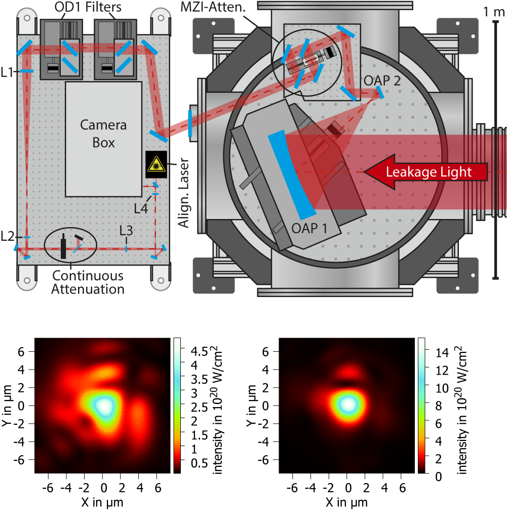
Figure 6 Layout of the petawatt target area sensor (top). The leakage of the last turning mirror before the target chamber is used to monitor the beam quality as close as possible to the laser–matter interaction experiment. A closed loop with a full-aperture deformable mirror allows for the maximization of the focused intensity on the target. The focal spots without (bottom left) and with (bottom right) this optimization loop are shown. Note that we quantify the spot quality in absolute terms of intensity instead of a relative Strehl ratio due to high-order spatial frequencies on the surface of the focusing optic, which is still to be characterized. This figure is reproduced from Ohland et al. [ Reference Ohland, Eisenbarth, Zielbauer, Zobus, Posor, Hornung, Reemts and Bagnoud40] with the permission of the authors.
2.4 System control and shot documentation
To allow for standardized operation by the laser crew, the components of PHELIX are monitored and controlled remotely by the PCS. The PCS is based on the CS-framework, an in-house development at GSI[ Reference Beck, Blaum, Brand, Herfurth and Schwarz41], which uses an object-oriented approach, is scalable, distributed, event driven and freely available under the terms of the GNU Public License[ 42]. The PCS is realized in the programming language LabVIEW. It handles roughly 10,000 process variables and the library comprises about 150 classes. It runs distributedly over 40 personal computers and controls all the different devices, such as cameras for observation and alignment, powermeters, waveplates, optics on translation stages, motorized mirror axes, screens and shutters, as well as the pulsed power systems of the pre- and MA stages, which are implemented through their respective classes. The relatively straightforward routine alignment and the highly complex shot procedure using the sequencer can be carried out remotely via the PCS from the PHELIX control room through a graphical user interface, an example of which can be seen in Figure 7. In addition to being the machine–user interface, the PCS also contains the possibility to run elaborate predefined procedures, such as closed-loop wavefront optimization routines necessary for the wavefront correction (cf. Section 2.3) or the automatic compensation of beam pointing and timing drifts in the frontend area.
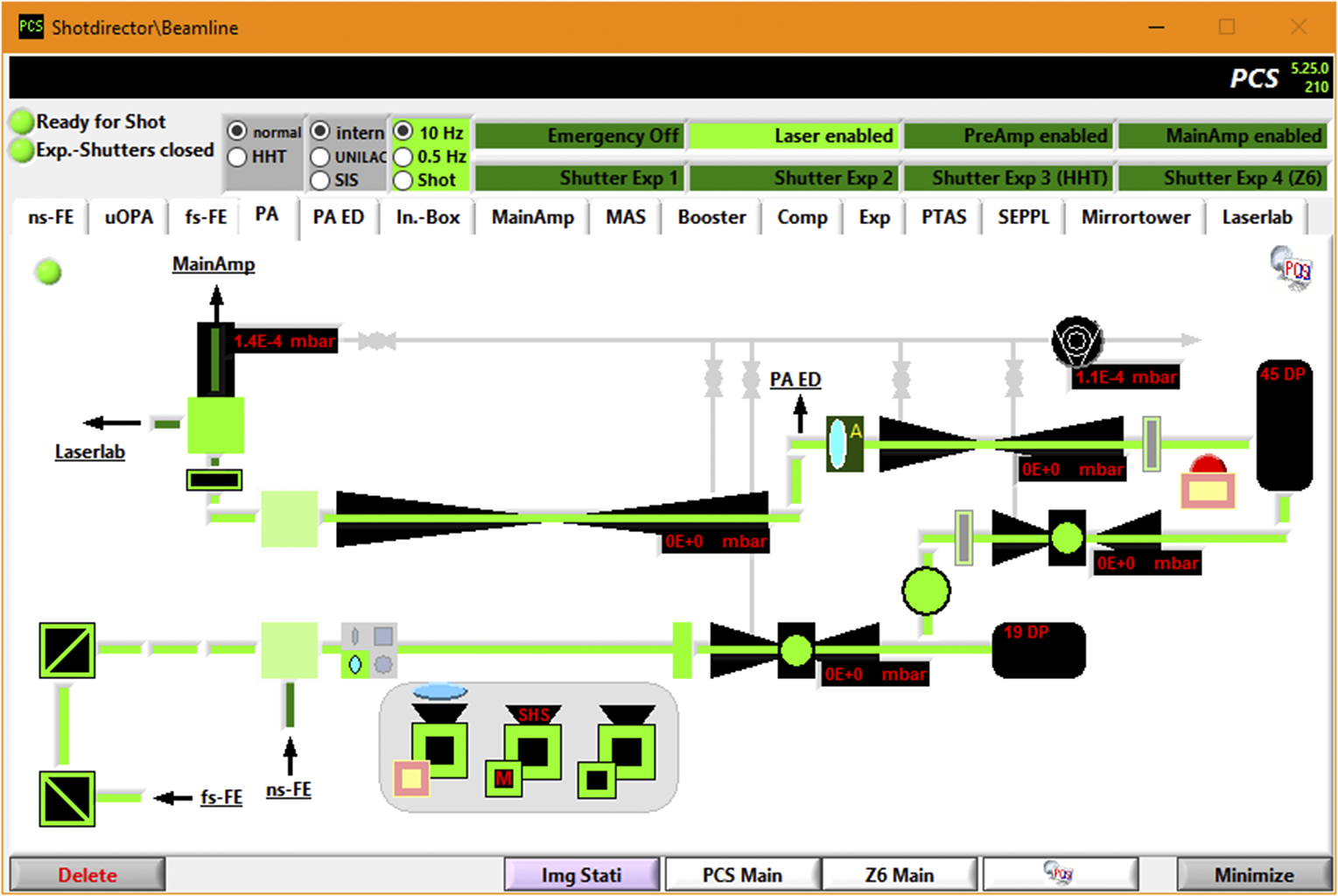
Figure 7 Example of the PCS graphical user interface. The different parts of the laser chain and diagnostics can be accessed on different tabs. In the picture the preamplifier stage is shown.
In order to document the system parameters of each event, such as PA test shots, full-energy shots and ‘snap shots’, the PHELIX shot database (PSDB) has been developed. It is based on a versatile relational database structure and records the contents of each PCS element after an event and stores it under the consecutively increasing shot number. Following the typical facilities work structure, sets of shots are grouped in experimental campaigns, which are accessible worldwide by the respective users through a web interface or a well-defined application programming interface (API) – both developed with the Ruby on Rails framework. The PSDB contains the data of all PHELIX shots since 2012, amounting to approximately 23,000 event entries and in total over 30 million process values to date.
2.5 Petawatt target area
Following the first laser–matter interaction experiments using PHELIX in short-pulse operation in the PTA of the laser bay (cf. Figure 3), the need for a custom target chamber became clear. This was necessary to overcome the limitations of the previous interaction chamber in terms of spatial constraints and flexibility of the experimental setup, and has, in combination with additional radiation shielding, allowed one to fully exploit the PHELIX capabilities. A cuboid target chamber of 129 cm × 204 cm × 83 cm usable inner dimensions was designed and manufactured (VA-TEC GmbH). The 30 mm stainless steel walls became part of the shielding concept, which also included an overall of roughly 50 tons of steel shielding around the target area, as shown in Figure 8. Note that no significant activation of the chamber walls is observed during experiments. Inside the chamber, a target manipulator with xyz-translation axes and rotation around the vertical axis can be centred on various target positions. Two full-beam shutter valves (DN320) with sub-aperture windows provide two possible entry points for the PHELIX laser coming from the PW compressor. In the configuration for the highest intensity, an f = 400 mm, 22.5° off-axis parabolic (OAP) mirror is used to focus the PHELIX beam with $f$
/1.6. The full-aperture DM for wavefront optimization after the pulse compression, together with the new wavefront measurement station close to the target (PTAS) can be used in this configuration (cf. Section 2.3). After correcting for the remaining aberrations in a closed loop, the highest intensity of around
$f$
/1.6. The full-aperture DM for wavefront optimization after the pulse compression, together with the new wavefront measurement station close to the target (PTAS) can be used in this configuration (cf. Section 2.3). After correcting for the remaining aberrations in a closed loop, the highest intensity of around $1.4\times {10}^{21}\ \mathrm{W}/{\mathrm{cm}}^2$
can be reached.
$1.4\times {10}^{21}\ \mathrm{W}/{\mathrm{cm}}^2$
can be reached.
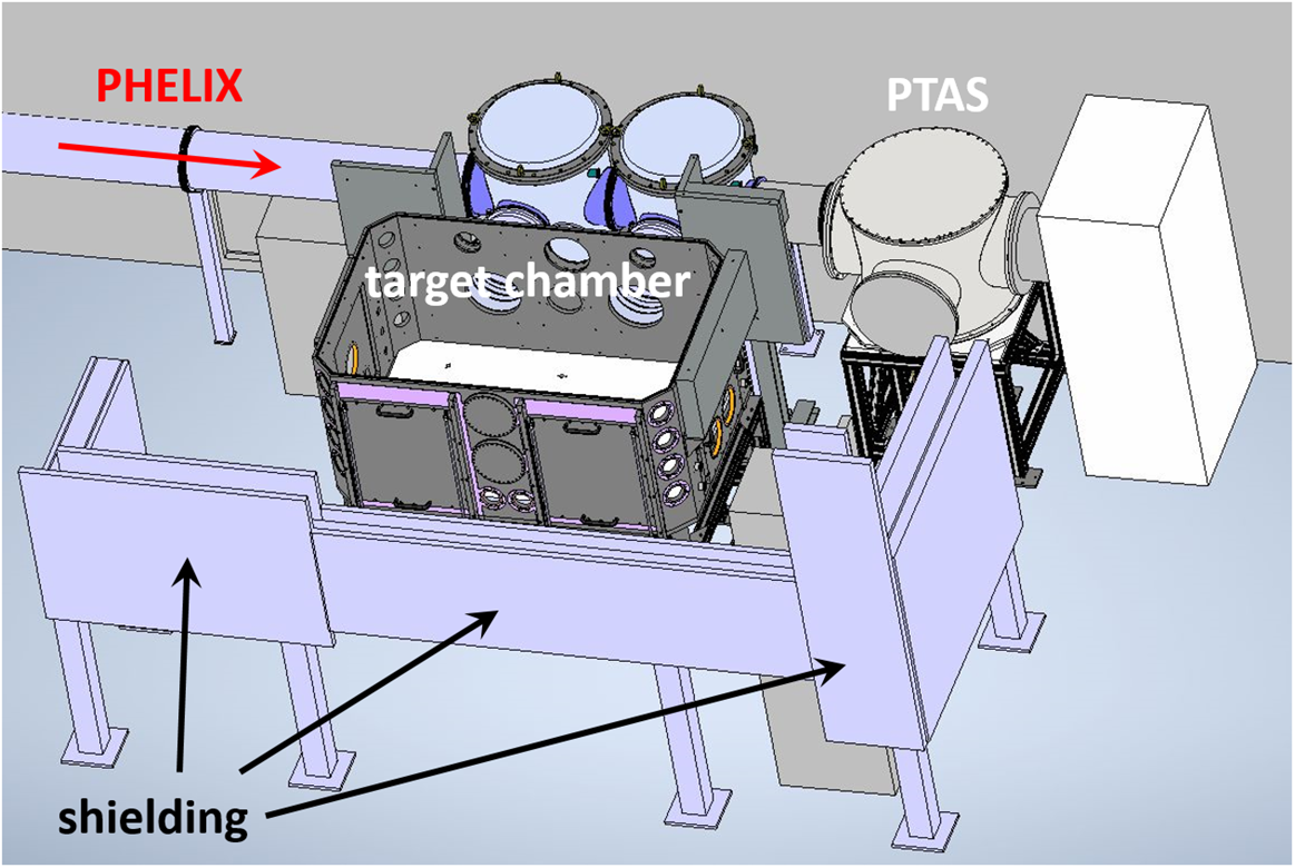
Figure 8 3D-model of the petawatt target area served by PHELIX. The target chamber has two entrance possibilities for the laser beam(s), which allows one to accommodate very diverse and highly complex experimental setups.
The versatility of the PTA target chamber allows for several beam geometries to be realized, ranging from the use of one full-aperture beam focused with the short focal length OAP as described above to multi-beam experiments combining the PHELIX short and long pulses. As an example, Barbato et al. [ Reference Barbato, Atzeni, Batani, Bleiner, Boutoux, Brabetz, Bradford, Mancelli, Neumayer, Schiavi, Trela, Volpe, Zeraouli, Woolsey and Antonelli43] used the sub-aperture ns-pulse to drive a shock and synchronized to this the sub-ps pulse, also sub-aperture, to drive an X-ray source for X-ray radiography and phase-contrast imaging. In a different experiment Rosmej et al. [ Reference Rosmej, Gyrdymov, Guenther, Andreev, Tavana, Neumayer, Zaehter, Zahn, Popov, Borisenko, Kantsyrev, Skobliakov, Panyushkin, Bogdanov, Consoli, Shen and Pukhov12] used a low-energy ns-prepulse before the high-energy PHELIX short pulse focused by a long-focal-length OAP (f = 1500 mm, 45°) to control the plasma conditions in a near-critical-density target for electron acceleration. For multi-beam experiments the typical jitter between pulses is less than 6 ps if the pulses are derived from the same frontend (typically fsFE), and less than 500 ps if the two frontends are used in combination.
Since most experiments require access to the detectors or targets between full-energy shots, it is important that the venting and pumping-down cycle of the target chamber is reasonably short. The combination of a $350\ {\mathrm{m}}^3/\mathrm{h}$
roughing screw pump with two turbo pumps of 2200 and 600 L/s backed by a
$350\ {\mathrm{m}}^3/\mathrm{h}$
roughing screw pump with two turbo pumps of 2200 and 600 L/s backed by a $35\ {\mathrm{m}}^3/\mathrm{h}$
scroll pump allows for a pump-down time from ambient pressure to the shot vacuum limit of
$35\ {\mathrm{m}}^3/\mathrm{h}$
scroll pump allows for a pump-down time from ambient pressure to the shot vacuum limit of ${5\times {10}^{-5}\ \mathrm{mbar}}$
in 25 min. The pump-down process has been fully automated, allowing experiment users a safe and efficient use of the vacuum system.
${5\times {10}^{-5}\ \mathrm{mbar}}$
in 25 min. The pump-down process has been fully automated, allowing experiment users a safe and efficient use of the vacuum system.
While most current experiments at PHELIX use solid targets in complex target assemblies, this type of targetry will not be compatible with the higher repetition rates that are envisaged for the mid-term future[ 44]. It would therefore be desirable if targets, such as gas jets, that are intrinsically suited to high repetition rates and applied routinely in ultra-short-pulse systems, could be adapted to the PHELIX pulse parameters. Such studies have already been started, either by applying high backing pressure of the order of a hundred to several hundred bars to the gas jet in order to reach high enough densities[ Reference Puyuelo-Valdes, Henares, Hannachi, Ceccotti, Domange, Ehret, d’Humieres, Lancia, Marques, Ribeyre, Santos, Tikhonchuk and Tarisien45] or by tailoring the gas jet using additional laser-driven shock fronts[ Reference Chen, Vranic, Gangolf, Boella, Antici, Bailly-Grandvaux, Loiseau, Pepin, Revet, Santos, Schroer, Starodubtsev, Willi, Silva, d’Humieres and Fuchs46, Reference Marques, Lancia, Loiseau, Forestier-Colleoni, Tarisien, Atukpor, Bagnoud, Brabetz, Consoli, Domange, Hannachi, Nicolai, Salvadori and Zielbauer47].
Recent additions to the capabilities in the target area include an off-harmonic probe laser (SEPPL), seeded by the uOPA pump laser system[ Reference Zobus, Brabetz, Loeser, Albach, Siebold and Bagnoud28], with precise timing and highly variable pulse duration, ranging over more than three orders of magnitude from 3.5 ps up to 10 ns, at pulse energies in the mJ range[ Reference Hornung, Zobus, Lorenté, Brabetz, Zielbauer and Bagnoud48]. The frequency-doubled (515 nm) probe laser enables different diagnostic methods, such as side-viewed interferometry or streaked shadowgraphy. In the specific setup, using a 2 mm probing spot in the plane of the target of 2 mm width, a ratio between the signal and self-emission larger than 110 is measured. In addition, the delay to the main pulse can be tuned by ±200 ns, also including zero delay, while maintaining a root mean square (RMS) jitter between the probe and the main pulse below 2 ps.
3 New high-energy beamline for studies of matter at high-energy density
One of the unique features of the infrastructure and facilities at GSI is the possibility to carry out experiments combining the PHELIX pulses with the heavy-ion beam of the accelerator. While this combination has been possible with the ion beam from UNILAC at the Z6 experiment area[ Reference Bagnoud, Aurand, Blazevic, Borneis, Bruske, Ecker, Eisenbarth, Fils, Frank, Gaul, Goette, Haefner, Hahn, Harres, Heuck, Hochhaus, Hoffmann, Javorkova, Kluge, Kuehl, Kunzer, Kreutz, Merz-Mantwill, Neumayer, Onkels, Reemts, Rosmej, Roth, Stoehlker, Tauschwitz, Zielbauer, Zimmer and Witte1, Reference Cayzac, Frank, Ortner, Bagnoud, Basko, Bedacht, Blaeser, Blazevic, Busold, Deppert, Ding, Ehret, Fiala, Frydrych, Gericke, Hallo, Helfrich, Jahn, Kjartansson, Knetsch, Kraus, Malka, Neumann, Pepitone, Pepler, Sander, Schaumann, Schlegel, Schroeter, Schumacher, Seibert, Tauschwitz, Vorberger, Wagner, Weih, Zobus and Roth3] (cf. Figure 1), the low ion energy and temporal structure of the ion bunch only allow for experiments in which the ions act as a probe (e.g., to measure stopping power), but are not powerful enough to be used to change the thermodynamic state of the target. In these experiments the nanosecond laser pulses were used as a driver to generate plasma states. In contrast, exploiting the energy deposition of heavy ions, such as those available from GSI’s heavy-ion synchrotron SIS18 and FAIR in the future, will allow for the heating of mm-sized samples to thousands of Kelvin and eventually to eV-temperatures. This will constitute a novel, complementary approach to the generation of high-energy-density states of matter, allowing for spatially and temporally uniform conditions, close to local thermodynamical equilibrium[ Reference Schoenberg, Bagnoud, Blazevic, Fortov, Gericke, Golubev, Hoffmann, Kraus, Lomonosov, Mintsev, Neff, Neumayer, Piriz, Redmer, Rosmej, Roth, Schenkel, Sharkov, Tahir, Varentsov and Zhao19]. In order to observe the behaviour of matter under such extreme conditions, laser-driven X-rays present themselves as powerful probes, which enable the detection of structural changes in the sample volume by XRD[ Reference Kalantar, Belak, Collins, Colvin, Davies, Eggert, Germann, Hawreliak, Holian, Kadau, Lomdahl, Lorenzana, Meyers, Rosolankova, Schneider, Sheppard, Stölken and Wark49] or the bulk temperature using XRTS[ Reference Glenzer and Redmer50].
We have recently implemented a high-energy laser beamline, guiding the long-pulse beam of PHELIX to the HHT experimental area (cf. Figure 2). The HHT cave is located downstream of the SIS18 accelerator ring, which has been upgraded in preparation for seeding the future SIS100 ring of FAIR. Thus, in addition to the high-intensity ion beam, high-energy laser pulses with up to 200 J of pulse energy with ns-pulse duration at 527 nm wavelength are now available in the HHT cave, temporally synchronized with the heavy-ion beam, allowing for combined experiments. In the following sections we will give details of the beamline architecture and performance.
3.1 Beamline layout and technical solutions
As shown in Figure 3, the PHELIX pulse can be steered towards the HHT experimental cave by choosing the appropriate mirrors at the switchyard after the Faraday isolator. In order to maintain the beam quality during the long beam-transport path, a long-focal-length lens telescope is used for relay imaging. The focal lengths and the positions of the telescope are chosen in a way to relay the image plane of the MA telescope into the HHT experiment area. The first lens has a diameter of 350 mm, thereby supporting the full beam aperture, and a focal length of approximately 30 m. The second lens has a diameter of 200 mm and a focal length of roughly 15 m, resulting in an overall demagnification of the beam by about a factor of 2. Both lenses have been manufactured by asphericon GmbH (Jena, Germany) and are AR (anti-reflection) coated for 1053 nm. In order to ensure a controlled environment, the beam transport takes place in vacuum provided by a turbomolecular pump (Edwards STPiX457) backed by a multi-stage roots pump (Pfeiffer ACP-40). Pressures in the low 10–5 mbar range are reached after a few hours of pumping. The beam enters the vacuum system right after the first lens, which is still located in a clean-room environment in the PHELIX building. All optical components that follow, with the exception of the beam diagnostics, are located in the vacuum. For stability reasons, all mounts are decoupled from the vacuum vessels to avoid external vibrations to couple into these, and displacement as a consequence of the pumping procedure and thermal effects to affect the alignment.
After the collimation of the beam by the second telescope lens, a DKDP (potassium dideuterium phosphate) crystal is used for second-harmonic generation (SHG). Details of the performance are given in Section 3.2. The remaining unconverted fundamental and the SHG beams are then separated by a dichroic mirror. Since a clean and controlled environment is essential for the optics, in particular those that are not in vacuum, a clean-room cabin has been built in the experiment hall of the heavy-ion synchrotron to house the diagnostics setup and also the vacuum chambers for a turning mirror, the collimation lens, the SHG crystal and the dichroic mirror (cf. Figure 2). The leakage of the dichroic mirror is used for diagnostics of both the fundamental and the second-harmonic beams at the HHT sensor (HHTS), as depicted in Figure 3. This diagnostic section consists of a five-lens bichromatic Galilei telescope for demagnifying both the fundamental and second-harmonic light. A subsequent set of dichroic mirrors in combination with long- and short-pass filters, respectively, splits the two wavelengths into separate beam paths. Each path consists of two attenuator units and two Kepler telescopes for further beam size reduction and image transport to a camera unit (CamBox). The attenuator unit is an all-reflective motorized mirror system providing attenuation factors 1 to ${10}^{-4}$
(optical densities 1–4), allowing for the characterization of both beams in the alignment mode as well as in full-energy shots. An additional output port allows the measurement of the pulse energy. The CamBox consists of a well-calibrated optical setup of three cameras, allowing for the measurement of the near-field and far-field distribution as well as the wavefront using the Shack–Hartmann principle. In addition, a part of the incoming light is fed into an optical fiber for the measurement of the temporal pulse profile using fast photodiodes.
${10}^{-4}$
(optical densities 1–4), allowing for the characterization of both beams in the alignment mode as well as in full-energy shots. An additional output port allows the measurement of the pulse energy. The CamBox consists of a well-calibrated optical setup of three cameras, allowing for the measurement of the near-field and far-field distribution as well as the wavefront using the Shack–Hartmann principle. In addition, a part of the incoming light is fed into an optical fiber for the measurement of the temporal pulse profile using fast photodiodes.
The non-converted fundamental laser light is dumped in a specially designed light trap in order to strongly suppress back-reflected stray light, which could disturb the diagnostics systems. After the SHG beam has been separated from the fundamental light, it is further transported to the HHT cave using three 10" high-reflection mirrors for 527 nm. Before the last mirror, the beam is focused using a 1.8-m-focal-length lens of 200 mm diameter with an AR coating for 527 nm (Knight Optical Ltd.). With a beam diameter of about 15 cm, this corresponds to a focusing around $f$
/13, which is very similar to that at the Z6 experimental area. After the last turning mirror, the beam passes through two vacuum windows, the first one closing off the laser beamline vacuum system and the second one to couple into the HHT target chamber, with a distance of approximately 10 cm between them. The target chamber is equipped with a mechanically decoupled breadboard of 1.1 m × 1.1 m in size. Three access ports allow easy access for the setup of experimental equipment. The target chamber is separated from the ion beamline by a titanium foil window. Figure 9 shows a picture of the last part of the PHELIX-HHT beamline, in which the vacuum boxes for the last two turning mirrors and the focusing lens as well as the target chamber and the tube, coupling the focused PHELIX laser beam into the chamber, can be seen.
$f$
/13, which is very similar to that at the Z6 experimental area. After the last turning mirror, the beam passes through two vacuum windows, the first one closing off the laser beamline vacuum system and the second one to couple into the HHT target chamber, with a distance of approximately 10 cm between them. The target chamber is equipped with a mechanically decoupled breadboard of 1.1 m × 1.1 m in size. Three access ports allow easy access for the setup of experimental equipment. The target chamber is separated from the ion beamline by a titanium foil window. Figure 9 shows a picture of the last part of the PHELIX-HHT beamline, in which the vacuum boxes for the last two turning mirrors and the focusing lens as well as the target chamber and the tube, coupling the focused PHELIX laser beam into the chamber, can be seen.
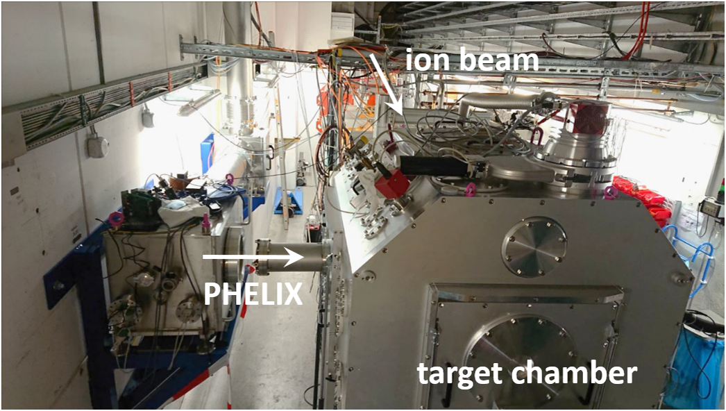
Figure 9 Photograph of the HHT experiment area downstream of the SIS18 heavy-ion synchrotron, showing the target chamber and the PHELIX beamline.
3.2 Efficient frequency doubling
In order to achieve efficient frequency doubling, the beamline contains a 200-mm-diameter DKDP crystal with 70% deuteration and a thickness of 17 mm, cut for type II phase matching (Gooch & Housego). It was designed to allow for SHG conversion efficiencies of more than 75% for the PHELIX parameters at HHT (e.g., 275 J pulse energy at the MAS and 2 ns pulse duration). The crystal design was supported by our in-house-developed simulation tool, which was then also validated by the experimentally achieved results[ Reference Malki21]. This code handles the 2D intensity distribution of the beam, as it impinges on the SHG crystal, and uses the split-step method to account for the SHG process and the propagation of the respective waves. To obtain the SHG behaviour in every step, the coupled wave equations are solved numerically by employing the fourth-order Runge–Kutta method. In this calculation, we take into account the effects of spatial walk-off and wavefront distortions, but the effects of diffraction are neglected, which is justified by the geometry and beam aspect ratio. The temporal pulse shape is taken into account by running multiple simulations assuming temporal pulse slices of rectangular shape. The total output energy is found by adding the results of all simulations together. An exemplary temporal pulse shape, measured after the MA, is shown in the inset of Figure 10.
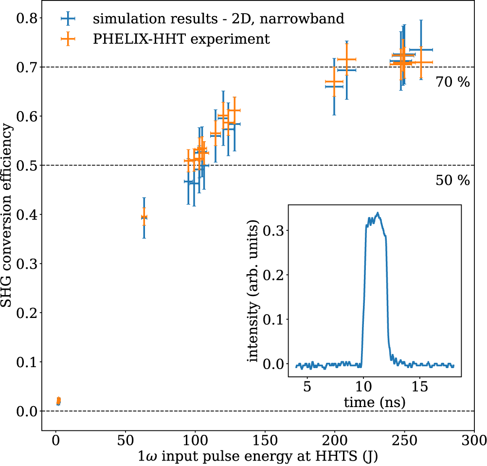
Figure 10 Second-harmonic generation in the PHELIX-HHT beamline showing the conversion efficiency at the HHTS. The inset shows a typical temporal shape of the PHELIX narrowband pulse.
Figure 10 shows the doubling efficiency of the SHG crystal in the HHT beamline and the comparison with the calculations using the experimental parameters. The experimental values for the input and output energies are determined from indirect on-shot measurements, for which the calibration factors were measured separately. In addition, the beamline transmission to the SHG crystal was experimentally determined, allowing for inferring the input energy on the SHG crystal using the cross-calibrated measurement at the MAS, located at the end of the MA. The uncertainties of these measurements originate from the uncertainty given by the calorimeters and lead to the error bars in Figure 10. The upper and lower limits of the energy incident on the SHG crystal are then used as input to the simulation and lead to the vertical error bars of the simulation data points. The error bars of the calculations and the experimental points overlap for all shots.
As can be seen in Figure 10, the conversion efficiency rises quickly when increasing the input energy. It already exceeds 50% for 100 J square pulses of 2 ns duration, and saturates above 200 J of input energy. The nominal energy of 200 J in the frequency-doubled pulse is reached for about 270 J of input energy, showing a conversion efficiency of more than 70%, close to the design point of the system, and also compares well with the design goal of the crystal and with performances found in similar systems[ Reference Linford, Johnson, Hildum, Martin, Snyder, Boyd, Smith, Vercimak, Eimerl and Hunt51– Reference Phillips, Banerjee, Ertel, Mason, Smith, Butcher, De Vido, Edwards, Hernandez-Gomez and Collier54]. The 200 J SHG output is the upper limit allowed by the beamline design, which is limited by the laser-induced damage threshold of the crystal coating and the coatings of the transport optics.
3.3 Laser-driven X-ray generation
Figure 11 shows the intensity distribution of the focal spot in the HHT target chamber. For pulses with the nominal energy of 200 J in the second harmonic, an intensity of the order of a few ${10}^{15}\ \mathrm{W}/{\mathrm{cm}}^2$
is reached. We have used these pulses to demonstrate the feasibility of X-ray generation, and they are suitable for the envisaged diagnostic methods of the heavy-ion-heated states. This commissioning study was mainly concerned with XRD and XRTS, which require intense narrowband line radiation. We have therefore irradiated mid-Z metal foil targets (Ti, V, Cr) and observed the X-ray emission from the laser-produced plasma using a highly oriented pyrolytic graphite (HOPG) crystal in the spectral range of 4–6 keV. We obtained intense line radiation from the 1s-2p transition in He-like ions (He–
${10}^{15}\ \mathrm{W}/{\mathrm{cm}}^2$
is reached. We have used these pulses to demonstrate the feasibility of X-ray generation, and they are suitable for the envisaged diagnostic methods of the heavy-ion-heated states. This commissioning study was mainly concerned with XRD and XRTS, which require intense narrowband line radiation. We have therefore irradiated mid-Z metal foil targets (Ti, V, Cr) and observed the X-ray emission from the laser-produced plasma using a highly oriented pyrolytic graphite (HOPG) crystal in the spectral range of 4–6 keV. We obtained intense line radiation from the 1s-2p transition in He-like ions (He– $\alpha$
) from different target materials (Ti, V, Cr), the spectra of which are shown in Figure 12. The estimated total conversion efficiencies amount to
$\alpha$
) from different target materials (Ti, V, Cr), the spectra of which are shown in Figure 12. The estimated total conversion efficiencies amount to ${10}^{-4}-{10}^{-3}$
, values similar to those obtained at comparable laser facilities[
Reference Ruggles, Porter, Rambo, Simpson, Vargas, Bennett and Smith55].
${10}^{-4}-{10}^{-3}$
, values similar to those obtained at comparable laser facilities[
Reference Ruggles, Porter, Rambo, Simpson, Vargas, Bennett and Smith55].
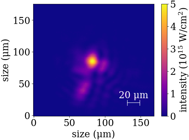
Figure 11 Intensity distribution in the focal spot of the PHELIX beam at HHT area.

Figure 12 X-ray line-emission spectra from different mid-Z metal targets generated at HHT using the PHELIX ns-pulse.
We have thus demonstrated the capability to drive X-ray sources with the PHELIX ns-pulses at the HHT experimental station, which will enable a wide range of X-ray-based probing schemes for HED experiments. Radiographic imaging, for example, is widely used to image the density distribution during the rapid hydrodynamic evolution of the sample[ Reference Döppner, Swift, Kritcher, Bachmann, Collins, Chapman, Hawreliak, Kraus, Nilsen, Rothman, Benedict, Dewald, Fratanduono, Gaffney, Glenzer, Hamel, Landen, Lee, LePape, Ma, MacDonald, MacPhee, Milathianaki, Millot, Neumayer, Sterne, Tommasini and Falcone56]. XRD allows for the observation of changes of the lattice constant due to thermal expansion and the observation of solid–solid phase transitions[ Reference Kalantar, Belak, Collins, Colvin, Davies, Eggert, Germann, Hawreliak, Holian, Kadau, Lomdahl, Lorenzana, Meyers, Rosolankova, Schneider, Sheppard, Stölken and Wark49], and indicates melting of heated targets[ Reference White, Kettle, Vorberger, Lewis, Glenzer, Gamboa, Nagler, Tavella, Lee, Murphy, Gericke and Riley57]. Furthermore, the sample temperature can be inferred from the diffracted intensity via the Debye–Waller factor[ Reference White, Vorberger, Brown, Crowley, Davis, Glenzer, Harris, Hochhaus, Le Pape, Ma, Murphy, Neumayer, Pattison, Richardson, Gericke and Gregori58] or the ion–ion structure factor measured in XRTS[ Reference Glenzer and Redmer50, Reference Descamps, Ofori-Okai, Appel, Cerantola, Comley, Eggert, Fletcher, Gericke, Goede, Humphries, Karnbach, Lazicki, Loetzsch, McGonegle, Palmer, Plueckthun, Preston, Redmer, Senesky, Strohm, Uschmann, White, Wollenweber, Monaco, Wark, Hastings, Zastrau, Gregori, Glenzer and McBride59].
3.4 Synchronization of PHELIX to the SIS18 ion bunches
In order to allow for combined experiments using both the ion beam from the SIS18 and the PHELIX laser pulses, the ion bunch and the laser pulse have to arrive at the experiment reproducibly at the same time. This task is not straightforward, as both are large-scale complex machines and each requires a set of timing and trigger signals for operation that are fundamentally different from each other; therefore, coupling the two systems is a challenging task that requires expert knowledge on both sides. In the usual sense, the term synchronization is used when the clock signals of two systems are locked to each other, as in, for example, two laser oscillators or a laser oscillator and the linear heavy-ion accelerator UNILAC at GSI. However, the precise arrival time of the ion bunch from SIS18 at the experimental station cannot be derived from such a common clock. If the SIS18 radio-frequency (rf) cavities are operated at the first harmonic, a single bunch of ions at high energy – close to the speed of light – circulates in the ring with a revolution frequency slightly above 1 MHz. The bunch is extracted from the ring using a ‘kicker magnet’, a beamline element used for steering the ion beam, which must be fired in the so-called bunch gap. Thus, the extraction time of the bunch depends on two things. Firstly, the kicker timing allows us to select a certain revolution of the ion bunch and only provides extraction windows in units of roughly 1 μs. Secondly, the phase of a bunch in the ring is defined by the rf-phase, which needs to be accessed in order to know the extraction time of the bunch. In the past, this information was not available. However, recently, the new bunch-to-bucket (b2b) transfer system[ Reference Bai60] has been developed at GSI in preparation for FAIR[ 18]. Here, the bunches from SIS18 will be extracted and injected into the centre of rf-buckets in the new SIS100 ring. The b2b system achieves this by precisely (<1 ns) measuring the rf-phase in both rings about 1.5 ms prior to the transfer, at the beginning of the extraction flat-top. This allows for the prediction of the phase of the ion bunch, the calculation of the kicker timings and the announcement of the precise extraction time by sending messages via the White Rabbit network of the General Machine Timing (GMT) system[ Reference Prados, Bär, Beck, Hoffmann, Kurz, Rauch, Terpstra, Zweig and Kreider61, Reference Kurz62] about 500 μs ahead of extraction. In addition to transfers between ring machines, the b2b system also handles the extraction of ion bunches from SIS18 to fixed target stations, such as the one located in the HHT cave, and thus this new development has made the necessary signals available to synchronize the PHELIX pulses to the ion bunch. The b2b system has been in routine operation at GSI since the beam-time in 2022, which opened up the possibility for testing the synchronization of the ion beam and the laser beam in the HHT cave.
Triggering the PHELIX laser is a two-stage process in which a FAIR timing receiver node (FTRN) is used to generate the two trigger signals. The first low-voltage transistor–transistor logic (LVTTL) signal is derived from timing messages distributed by the GMT system about 3 ms prior to extraction, early enough to trigger the pumping flashlamps at PHELIX. The second LVTTL signal is derived from the extraction announcement by the b2b system used for precisely (jitter less than 1 ns) triggering the ns-frontend. The laser pulse to be amplified is then delivered into the laser chain in which its propagation time is fixed by the optical path, which usually has an uncertainty several orders of magnitude below the 1-ns timescale and can therefore be taken as ‘exact’ compared to the ion bunch. The timing of the PHELIX laser pulse reaching the target chamber at HHT is expected to be reproducibly set and varied relative to the ion-bunch arrival with an expected uncertainty at the 1-ns level. Figure 13 schematically shows the necessary signals derived from the timing system to couple the two machines.
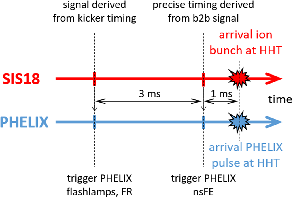
Figure 13 Schematic representation of the timing signals used for synchronization of the SIS18 ion bunch to the PHELIX laser pulse.
To verify the precision of the scheme triggering PHELIX with the accelerator timing signals, we used a diamond detector to register the arrival time of the ion bunch in the HHT target chamber and an optical photodiode to measure the laser arrival time. Additional delays introduced by the signal transport in the respective cables have been taken into account. In this way, we have shown that the laser pulse and the ion bunch arrive at the target chamber at the same time, within an uncertainty of 10 ns. This uncertainty originates in the difficulty defining the start of the ion bunch with a better accuracy than 10 ns due to the measurement method, which provides an upper limit to the uncertainty of the relative arrival times of the laser pulse and the ion bunch. We believe, however, that in reality this jitter is significantly smaller by up to an order of magnitude. However, since the duration of the ion bunch is of the order of 500 ns, even an uncertainty of 10 ns can easily be tolerated by the envisaged experiments.
4 Conclusions and outlook
In summary, the current status of the high-energy laser facility PHELIX has been presented. Continued development work has been carried out on the system during the past decade, which makes PHELIX attractive to a large number of international user groups to carry out experiments in the field of laser-driven secondary sources, as well as WDM research. Especially in the latter field, we have recently extended the capabilities of the infrastructure, allowing for laser-driven X-rays synchronized to the ion bunch from the GSI heavy-ion synchrotron SIS18. With this, we have established a new platform for X-ray diagnostics of heavy-ion heated matter, representing a complementary approach to WDM research as done, for example, with X-ray free electron lasers. The first combined experiments have been conducted recently, the results of which will be reported on in the near future[ Reference Hesselbach, Lütgert, Bagnoud, Belikov, Humphries, Lindqvist, Schaumann, Tauschwitz, Varentsov, Weyrich, Winkler, Yu, Zielbauer, Kraus, Riley, Major and Neumayer63, Reference Lütgert, Hesselbach, Schörner, Bagnoud, Belikov, Drechsel, Heuser, Humphries, Katrik, Lindqvist, Qu, Redmer, Riley, Schaumann, Schumacher, Tauschwitz, Varentsov, Weyrich, Yu, Zielbauer, Zs. Major and Kraus64].
Acknowledgements
The presented results have been achieved in the context of FAIR Phase-0 at GSI, Darmstadt (Germany), and include data of experiment P214 performed at the HHT target station. PHELIX receives funding from the European Union’s Horizon 2020 research and innovation programme via the transnational access and joint research activity programmes of Laserlab (grant agreement Nos. 871124 and 654148). Some of the development projects also receive funding from the European Union’s HORIZON-INFRA-2022-TECH-01 call under grant agreement number 101095207 (THRILL). The HHT target chamber, vacuum pumping system and envisaged target manipulator station have been financed via the BMBF ErUM-APPA collaborative research scheme (contract numbers 05P19RFFA1 – Goethe-Universität Frankfurt, 05P21RDFA2 – Technische Universität Darmstadt, 05P19SJFA1 and 05P21SJFA2 – Friedrich-Schiller-Universität Jena). The authors are grateful to the supporting departments at GSI. Here the authors wish to mention in particular Holger Brand for his continuous support with the PHELIX control system in both development and operation, and Dmitry Varentsov and Martin Schanz of the plasma physics department for their help with the HHT infrastructure.


 Open access