


Principles of Optical Filtering in Coherent Light
The analysis of the photographs has been made by a method already used in several earlier investigations (Reference Roetling and HammillRoetling and Hammill, 1962; Reference Pincus and DobrinPincus and Dobrin, 1966; Reference FontanelFontanel and others, 1967). Described in geometrical terms, the problem consists in transforming the photographs in a way which favours systems of cracks or crevasses having a given average direction. One can then recognize them more easily, and so can trace and study them. By sweeping systematically through all the directions in the plane, one can thus analyse a photograph in various ways and obtain a number of filtered prints in which one has chosen the directions for the various operations in the transformation. These processes are called filtering, and we speak of the resulting photographs as having been filtered in direction. The analogy with frequency filtering as used by electrical engineers, or with spatial frequency filtering in optics is apparent (Reference O’NeillO’Neill, 1956; Reference CroceCroce, 1956; Reference Maréchal and FrançonMaréchal and Françon, 1960). In our case the selection operates on the photographs in favour of the mean direction of elongated objects, whatever their position and whatever their number.
The optical principle which allows us to make this analysis is simple. It uses the diffraction pattern produced by a transparent object when it is illuminated in coherent light. Let us suppose we have set up such a transparent print and have illuminated it in a beam of parallel coherent light (such a beam is produced by a monochromatic source situated effectively a large distance away or by a laser). Now, following Huyghens, let us consider each point on the object to be acting as a source of secondary wavelets. Their intensity will depend on the transparency of the photograph at the point in question and their phase is the same everywhere. At large distances one can observe the interference pattern produced by the addition of the elementary light waves coming from all points of the photograph. In effect these add up differently in different directions according to the position of the points on the photograph from which they originate and according to the actual transparency at these points. If the photograph is the image of a grating that is to say there are regular alternations between parallel opaque and transparent bands, the diffraction pattern at large distances will be found to be concentrated in a plane passing through the axis of the beam of light coming from the source and perpendicular to the direction of the bands.
To return to an aerial photograph of a glacier, we now suppose that the photograph consists entirely of opaque and transparent bands; these bands need not be continuous, nor need they have a constant separation, furthermore as long as they remain effectively parallel to a given direction in the plane, their thickness need not be everywhere equal. In this case the diffraction pattern at a large distance is not entirely concentrated in the plane described above, but is nevertheless situated around this plane. It deviates from it less the more regular and more parallel the bands are. Finally if several systems of bands are present simultaneously on the photograph, the diffraction pattern we observe will be the superposition of the patterns corresponding to each of the systems by themselves. Each of the individual patterns will be situated around a plane passing through the axis of the initial beam and perpendicular to the direction of the bands in the system under consideration (Fig. 1).
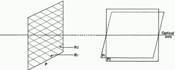
Fig. 1. Diffraction pattern produced at large distances by two superimposed gratings situated in the same plane. p is the plane of the gratings r1 and r2, p1 and p2 are the planes into which the light diffracted by r1 and r2 is concentrated at infinity
This shows that the diffraction pattern at a large distance allows us to analyse a photograph consisting of several families of alignments, each of these families producing a concentration of Iight around a plane passing through the axis of the initial beam. The orientation of this plane depends only on the direction of the family in question.
Now let us consider how to record the diffraction patterns and how to use them to filter photographs. It is apparent that one cannot go to infinity to photograph the diffraction patterns, but by making the beam of light convergent, one can make them appear in a plane perpendicular to the axis of the initial beam. This plane cuts the axis at the point where the beam would have been focused if the photograph had been absent. The diffraction patterns will now appear to be concentrated on straight lines which are the intersections of the plane in question with the planes defined above. There are thus concentrations of light around straight lines perpendicular to the directions of the alignments on the photograph and situated in the plane perpendicular to the axis of the beam at the point where this would have been focused in the absence of the photograph. The distribution of light that one can observe in this place on a screen or can photograph on a plate, can be represented mathematically as the Fourier transform, or spectrum of the function which represents the transparency of the original photograph. Theorems concerning these spectra have been enunciated in specialized works (Reference BracewellBracewell, 1965; Reference GrauGrau, 1966). One can see in particular that the luminous intensity of the spectrum is independent of the position of the photograph provided this remains perpendicular to the axis of the beam.
Figure 2b represents the spectrum of the photograph shown in Figure 2a. This photograph, which is very regular, corresponds to the case of a grating. The spectrum is strongly concentrated around a straight line passing through its centre. By contrast Figure 3b gives the spectrum of the photograph shown in Figure 3a where the bands are irregular. The spectrum is more diffuse, but it is still distributed around a straight line perpendicular to the mean direction of the alignments. It is noticeable that the centre of the spectrum always consists of a luminous spot. This comes from light which has not been diffracted by the photograph, and serves to mark the axis of the beam. The cross centred on this spot is produced by the diffraction pattern of the light from the rectangular frame carrying the photograph.
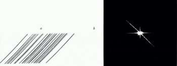
Fig. 2. Grating (Fig. 2a) and its spectrum (Fig. 2b)
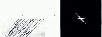
Fig. 3. Pseudo-grating (Fig. 3a) and its spectrum (Fig. 3b)
If we extend the arguments applied above to the spectrum, we appreciate that at a large distance we would observe the diffraction pattern which it would itself create. This diffraction pattern at infinity, if we bring it back to a finite distance, will occur in a plane known as the image plane, by a redistribution of the light that one can represent mathematically as the Fourier transform of the spectrum. But two Fourier transforms compensate each other, and the final result is an image of the photograph which served as object.
To sum up, we can see that using several converging lenses and coherent light for illumination one can make a transparent photograph project an image and at a certain place between them the spectrum of the original photograph appears (Fig. 4).
Any modification we impose on the spectrum will produce a corresponding effect on the image. But we have seen that the spectra of photographs consisting of families of dark and light bands which are more or less parallel and regular, consist of more or less broad lines passing through the centre of the spectrum. From this it is easy to see that if we remove from the spectrum one or more of these lines by means of an optical screen, we at the same time suppress from the image the corresponding family of bands, and we do this whatever their position on the original photograph. We thus have a method of obtaining simplified images in which one or more of the families of alignments have disappeared. This is the basis of the method we have used in the filtering of photographs of glaciers.
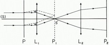
Fig. 4. Diagram showing the principle of the optical filtering apparatus. s is the source at infinity, p is the plane of the original photograph, l1 is a converging lens, p1 is the spectral plane where rays leaving p parallel to each other at any angle a converge, in particular undeviated rays converge to s′, the image of the source, l2 is another converging lens, and p2 is the plane of the filtered photograph
Apparatus
The apparatus used (Fig. 5) consisted of a gas laser, an optical system designed to widen the beam, an immersion-type film holder in which a reduced version of the photograph to be studied was placed, two converging lenses, a filter holder for the optical screens, and a photographic camera. A television camera allowed one to see the image entering the photographic camera by means of a removable mirror. It was therefore possible to see on the television screen an enlarged view of the result of filtering while the optical screen holder was being manipulated. When the result appeared satisfactory, the mirror was removed and a photograph taken. In this way a rapid analysis of an aerial photograph could be made and as many filtered photographs as seemed desirable could be taken. The filter holder allowed a sector of a circle centred on the point of intersection of the spectral plane with the axis of the beam to be raised into the spectrum. The angle of this sector could be varied from 10 to 40 degrees and it could be in any orientation. It was also possible to eliminate two independent sectors, the angle of each being variable from 10 to 20 degrees. One could also allow only a narrow sector of the spectrum through, removing all the rest (Reference Roetling and HammillRoetling and Hammill, 1962; Reference Pincus and DobrinPincus and Dobrin, 1966). This last type of filtering should only be used however for special purposes, for example in order to compile statistics of alignments oriented in different directions (Reference FontanelFontanel and others, 1967). Once the filtered photographs have been prepared, a process which only involves some photographic work and judgement to decide which photographs to take, one can study them at leisure, under a stereoscope if necessary since the relief has not been destroyed, and can compare them with the original photograph to examine the cracks and crevasses which the analysis has revealed.
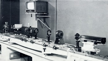
Fig. 5. The optical filtering apparatus FO-100 of the Institut Français du Pétrole
Description of the Southern Lobe of the Front of Jakobshavn Isbræ (Greenland)
Jakobshavn Isbræ is one of the most active glaciers in the world. Its front calves into a fjord which opens into Disko Bugt at about lat. 69° 10′ N., long. 50° 10′ W. (Fig. 6). The principal ice front which has a high rate of flow is separated by a chaotic zone ab (Fig. 7) from the southern lobe which dies out on dry land. The principal front calving into the fjord exhibits systems of wide crevasses parallel and perpendicular to the direction of flow d1. However the southern lobe is marked by curved crevasses parallel to the contour of this lobe, perpendicular to the local flow directions d2 and d3. It therefore seems as though the southern lobe must consist of a local spreading out or flooding of ice from the principal channel over some subglacial obstacle ab, in effect the continuation of the left bank of the glacier.
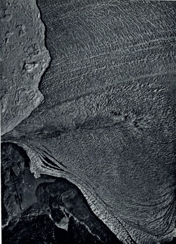
Fig. 6. Southern frontal lobe of Jakobshaan Isbræ. Reproduction specially authorized by the Director of the Geodetic Institute, Kobenhavn
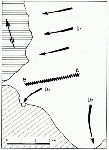
Fig. 7. Jakobshavn Isbræ; principal flow streams
The flow velocity vectors (Fig. 8), determined from repeated aerial photographic cover (Reference BauerBauer, in press), confirm this fact; they drop from 13 m./day for the principal stream to about 1 m./day for the southern lobe. Furthermore, even though the directions of the small flow velocities of the southern Lobe are less well determined than those of the principal stream, it can be said that their directions are identical; the southern lobe flows to the west just like the principal stream. Thus the flow of the southern lobe does not seem to be related to the directions d2 and d3 nor to the incurved crevasses.
Application of Optical Filtering in Coherent Light to the Photo-interpretation of Surface Features of Jakobshavn Isbræ
To resolve the apparent contradiction between the flow direction of the southern lobe of this glacier and the orientation of the incurved crevasses, we have used optical filtering in coherent light for a portion of the southern lobe using a different photograph from Figure 6, a photograph at a larger scale. First we note the loss of definition as compared with the original after diffraction without filtering (Fig. 9); this is normal because the illuminated photograph is a reduced negative of quite small dimensions which has been finally re-enlarged. This reconstituted original gives a spectrum consisting in part of some luminosity between north and west perpendicular to the families of crevasse patterns (Fig. 10).
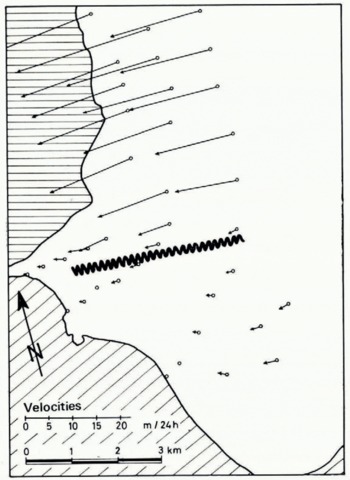
Fig. 8. Jakobshavn Isbræ; velocity vectors near the ice front
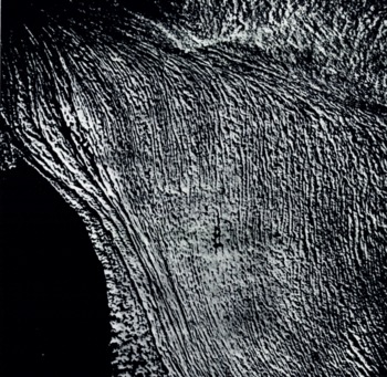
Fig. 9. Part of the southern lobe; original photograph reconstituted after diffraction but without filtering
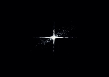
Fig. 10. Spectrum corresponding to Figure 9
Using optical screens we proceed to attenuate and even suppress these systems to see if other systems exist, systems originally drowned in the mass of crevasses. The elimination of directions between north 45° west and north 65° west makes a system parallel to the line ab appear; these are parallel to the flow of the southern lobe (Fig. 11). The spectrum of this photograph is given by Figure 12. An optical screen from north 30° west to north 10° west makes a network appear practically perpendicular to the line ab (Fig. 13). Its spectrum is given by Figure 14.
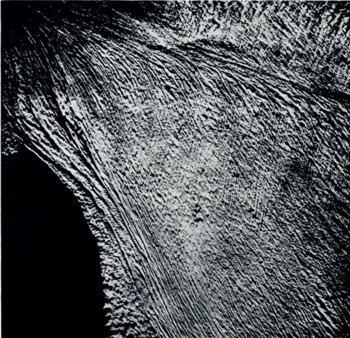
Fig. 11. Photograph after diffraction with an optical screen between north 45° west and north 65° west
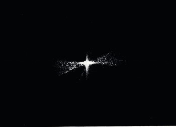
Fig. 12. Spectrum corresponding to Figure 11

Fig. 13. Photograph after diffraction with an optical screen between north 30° west and north 10° west
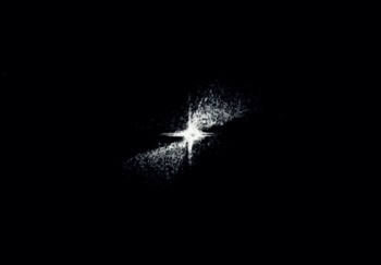
Fig. 14. Spectrum corresponding to Figure 13
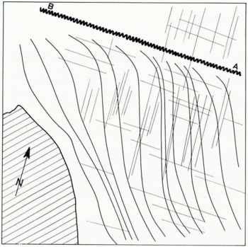
Fig. 15. Sketch map showing the incised pseudo-crevasses and the two systems of orthogonal crevasses
Stereoscopic study of a pair of original photographs shows that these two new directions are those of fine crevasses obliterated by the system of incurved crevasses to the point of preventing observation. Thus the technique of optical filtering has allowed us to discover two other crevasse systems which seem to be related to the flow of the southern lobe. And, as crevasses are related to the state of stress of the ice, and thus to the flow, we deduce that the incurved crevasses are not true crevasses at all, as a hasty examination of the original photograph had led us to think.
On re-examining the original photograph (Fig. 6), we see that these “incurved crevasses” become, at the edge of the glacier and near the edge at the end of d2 and d3, where the ice breaks up and flows into the marginal lakes, bands of black ice, ice loaded with morainic debris brought to the surface by ablation, a phenomenon that can be seen all along the edge of the ice sheet where it dies out on dry land. Moreover these bands of black ice become more and more bands of blue ice as one goes towards the interior (Reference von DrygalskiDrygalski, 1897; Reference Quervain and MercantonQuervain and Mercanton, 1925), and they are separated from each other by bands of white ice. The black ice (loaded with morainic debris) and the blue ice (without air bubbles) have a much lower albedo than the white ice (with air bubbles). It follows that the “incurved crevasses” consist of surface waves whose summits are formed by the white ice and whose troughs are the black or blue ice. As these bands can have thicknesses of up to several metres, and as ablation at these altitudes can also reach several metres of ice each melting season, these waves can have amplitudes of several tens of metres. Finally as these pseudo-crevasses are not related to the local flow dynamics, one can deduce that their formation must have taken place in the deep layers of the ice far from the edge of the Greenland ice sheet.
Conclusions
The examination of an aerial photograph of a glacier using the technique of optical filtering has allowed us to find surface crevasse systems practically impossible to discern at first sight because they were obliterated by other surface forms. The photo-interpretation of these latter forms in the light of the information obtained from filtered photographs, has allowed us to draw conclusions about both the nature and origin of these forms.
The use of the technique of optical filtering of aerial photographs of glaciers could be very fruitful in glaciology and in some cases could be developed side by side with the development of aerial photographic programmes for the glacierized regions of the world. It brings, in effect, an elegant and rapid solution to the problem of how to study the aerial photographs of glaciers which are accumulating continuously in data centres and whose interpretation very often still remains to be undertaken.


