Nomenclature
- ${A_{\rm{d}}}$
-
the droplet windward area, m2
- $d{A_0}$
-
infinitesimal area of far-field droplets, m2
- $dA$
$dA$
-
impingement area, m2
- C D
-
drag coefficient
- d d
-
the droplet diameter, m
- g
-
the gravity acceleration vector, m/s2
- h
-
the thickness of water film, m
- m d
-
the droplet mass, kg
- n
-
the unit normal vector
- p
-
air pressure, N/m2
- ${p_{\mathop{\rm d}\nolimits} }$
-
the normal dynamic pressure arising from impingement and splash, N/m2
- ${p_h}$
-
the hydrostatic pressure, N/m2
- ${p_l}$
-
the pressure of the liquid film, N/m2
- ${p_\sigma }$
-
the pressure caused by surface tension, N/m2
- R
-
Reynold stress tensor, N/m2
- Re d
-
the relative Reynold number
- U
-
air velocity vector, m/s
- U d
-
the droplet velocity vector, m/s
- ${{\bar{\boldsymbol{U}}}_l}$
-
average velocity of water film flow, m/s
- $\beta $
-
the local collection efficiency
- $\theta $
-
the inclined angle
- μ
-
air viscosity, kg/(m $ \cdot $
s)
 - $\rho$
-
air density, kg/m3
- $\rho$
d
-
the droplet density, kg/m3
- ${\rho _l}$
-
the density of the liquid film, kg/m3
- ${{\boldsymbol{\tau }}_{\rm{f}}}$
-
the film-gas interface shear stress, N/m2
- ${{\boldsymbol{\tau }}_{\rm{w}}}$
-
the film-wall interface shear stress, N/m2
1.0 Introduction
Aircraft icing can seriously degrade the aerodynamic performance of aircrafts, and even cause flight accidents, so it is crucial to investigate the effects of icing on aerodynamics by numerical computation, experiments or flight tests. Among these methods, the numerical methods are considered to be the most cost-effective and are increasingly used in aircraft icing research. There are by far many icing simulation software products, such as LEWICE [Reference Ruff and Berkowitz1], TRAJICE2 [Reference Gent2], ONERA [Reference Hedde and Guffond3] and FENSAP-ICE [Reference Beaugendre, Morency and Habashi4], among which LEWICE is the most well-known and widely used in the scientific research and engineering application. Through experiment, Andy, a researcher at NASA's Glenn Research Centre, [Reference Andy and Mark5] obtained a large database of ice shapes of swept wings and discovered the glaze and scallop ice geometry on swept wings. But for three-dimensional swept wings, it is difficult for LEWICE3D (the three-dimensional version of LEWICE) to get ice shapes similar to the experimental ice shapes [Reference Richard and Andy6], because LEWICE3D essentially bases on two-dimensional ice accretion computation, which can simulate the main two-dimensional characteristics except the spanwise features of ice shapes.
More attention should be paid to glaze ice shapes with surface water film on three-dimensional geometries. Yi [Reference Yi, Gui and Zhu7] established a numerical method to calculate the three-dimensional ice accretion and found that the three-dimensional effect of runback water caused by the swept wing significantly affects icing. Cao [Reference Cao, Ji and Si8], using CFX software, derived the control equations for the thin film flow based on the finite volume method, analysed the thin water film flow on the ice layer, which affects the three-dimensional ice accretion on the windward surface, and stated that the icing model with the water film flow could simulate the three-dimensional glaze ice well, while the authors focused on a three-dimensional straight wing and did not study the effects of the angle-of-attack and the angle of sweepback. Shen [Reference Shen, Lin, Yu, Bu and Du9] considered the air frictional force as the main factor driving the surface runback water streaming and established a fully three-dimensional ice accretion model to calculate ice shapes at engine inlet. Huang [Reference Huang, Nie and Cao10, Reference Cao, Huang and Yin11] simulated three-dimensional ice accretion on an aircraft wing, taking into account the runback water flow, but assumed that the flow direction of the film followed the air streamlines, without the momentum equation for the film flow, and without the effects of rebound and splash. Liu [Reference Liu, Qu, Cai and Pan12] developed a three-dimensional aircraft ice accretion model based on the numerical solution of the unsteady Stefan problem and showed that the lower ice horn grew significantly from the wing root to the wing tip of GLC-305 swept wing. Ahn [Reference Ahn, Jung, Myong, Shin and Habashi13] investigated ice accretion on the surface of an electrothermal anti-icing system around a rotorcraft engine air intake on the basis of FENSAP-ICE and experimental methods. Raj [Reference Raj, Esmaeilifar, Jeong and Myong14] presented a three-dimensional computational model to compute glaze ice accretion on complex configurations and investigated glaze ice accretion on a rotorcraft engine inlet. Li [Reference Sibo and Roberto16] presented an ice accretion simulation method over aircraft wings using a three-dimensional compressible Navier-Stokes solver, a Eulerian droplet flow field model, a mesh morphing model and a thermodynamic model. In most of the research on glaze ice with the effects of film flow mentioned above, the film flow models are constructed based on the extended heat transfer model proposed by Myers [Reference Myers15], which does not have the momentum equation for the film flow, i.e. the film velocity is not solved.
In the ice accretion process of glaze ice, we should first study the droplet movement and impingement process, then the film flow process and finally the icing process. The collision of particles can induce various phenomena. Using molecular dynamics, Kalweit et al. [Reference Marco and Dimitris17] investigated collision dynamics of nanoparticles for a broad range of impact factors and collision speeds and classified the collision dynamics into different collision modes and submodes: coalescence (sticking, slide-and-locking and droplet), stretching separation (normal stretching separation, stretching separation with satellite droplets and shearing off). They also found that the reflexive separation mode, which had been observed in macroscopic droplet collisions, did not occur for nanoparticles consisting of 10,000 (or less) atoms. For macroscopic droplets, through theoretical analysis and extensive experimental data, Bai et al. [Reference Bai, Rusche and Gosman18] proposed a splashing model for droplet impingement onto dry/wet surfaces, which included four impingement regimes: stick, rebound, spread and splash. Some work has been carried out to study the flow characteristics of the thin water film. Within the EXTICE project [Reference Mingione, Iuliano, Guffond and Tropea19], the problem of supper-cooled large droplet (SLD) simulation is addressed using both numerical and experimental tools, where the effect of the liquid film has been investigated. Alzaili [Reference Alzaili and Hammond20] investigates the thin water film characteristics by performing a series of experiments for different icing conditions. Three characteristics of the water film velocity, wave celerity and its wavelength for the thin water film have been studied. Leng [Reference Leng, Chang and Lian21] experimentally studied the characteristics of water film flow driven by wind shear and gravity, and presented a relational expression of the film thickness about air flow velocity, Reynold number of water film and inclined angle. Zhang [Reference Zhang and Hu22] studied the water film flow on NACA0012 aerofoil and measured the thickness of the water film by experimental method. Numerical methods have also been developed to study the effects of film flow, such as multiphase method [Reference Guo and Lian23], integral boundary-layer method [Reference Iuliano, Mingione, Petrosino and Hervy24, Reference Ellen, Jacco, Edwin and Harry25], finite volume method [Reference Cao, Ji and Si8] and finite area method [Reference Tuković26]. Guo [Reference Guo and Lian23] reported a new method to calculate water collection efficiency using a multiphase flow solver and found that splashing on the thin liquid film caused more mass loss than on a dry surface. In the EXTICE project, Iuliano [Reference Iuliano, Mingione, Petrosino and Hervy24] and Ellen [Reference Ellen, Jacco, Edwin and Harry25] developed an improved splashing model for the impact of SLD on a thin liquid film by using an integral boundary-layer method and assuming a linear velocity profile in the liquid layer, and numerically investigated the effect of the presence of a thin liquid film of water on the surface. Cao [Reference Cao, Ji and Si8] derived the control equations for thin film flow based on the finite volume method and simulated the three-dimensional glaze ice well with thin film flow. Finite volume methods can also be used to solve hyperbolic models for compressible two-phase flow [Reference Romenski, Drikakis and Toro27], in the paper the authors studied the water faucet test case, the Riemann problem with a sonic point and the water-air shock tube test case. While for incompressible thin film flow, the finite area method is a good choice. Beld [Reference Beld28] used OpenFOAM to model a surface film layer on NACA0012 aerofoil to more accurately simulate glaze ice. OpenFOAM [29] is free, open-source software for CFD from the OpenFOAM Foundation. It has an extensive range of features to solve complex fluid flows involving chemical reactions, turbulence and heat transfer and multiphase flow. Many studies on thin film flow have been conducted using the OpenFOAM finite area method and have shown the validation and accuracy of the algorithm in OpenFOAM, such as the investigation of rain effects on NACA0012 aerofoil [Reference Liu, Zhao, Shao and Shu30], the simulation of thin film fluid flow on rotating discs [Reference Petr, Bernhard, Doris and Helfried31], and the simulation of the gas-liquid separation process in an axial flow cyclone [Reference Deng, Zhang, Hou, Yu and Sun32], but few studies have been carried out on the film flow of aircrafts, especially for three-dimensional shapes. In this work, we adopt the thin-film assumption with a quadratic velocity profile to investigate the flow characteristics of the thin water film formed by droplet impingement on three-dimensional wings based on OpenFOAM, including the momentum equation of the film flow, with a two-way coupling between the droplet movement and the film flow, i.e. considering the interactions between the droplet movement and the film flow. We focus on the three-dimensional effects arising from the angle-of-attack (AOA) and the angle of sweepback, aiming to provide a new perspective for the study of three-dimensional swept wing icing. In this paper, numerical methods including air flow evaluation, droplet impingement computation and film flow simulation are presented in Section 2. The computation of droplet movement is validated by comparing the local collection efficiency of the two-dimensional MS-0317 aerofoil and the three-dimensional sphere in Section 3. The numerical simulation of the thin film flow is verified by the Nusselt solution of a plane with two inclined angles. The flow characteristics of the water film on the three-dimensional MS-0317 straight and swept wings, in particular the three-dimensional effects due to the angle-of-attack and sweepback, are investigated in Section 4.
2.0 Numerical methods
In this section, numerical methods for droplet impingement and film flow will be described. Firstly, the governing equations of air flow will be presented. Secondly, the computational method for droplet impingement will be introduced. Thirdly, the simulation approach for film flow will be discussed. Finally, the solution procedure will be outlined.
2.1 Air flow evaluation
In this work, Reynold Average Navier-Stokes (RANS) equations are used as the air flow control equations:
where
![]() $\rho$
,
U
and p are the density, velocity vector and pressure of air, respectively, and
R
is Reynold stress tensor. The steady-state solver simpleFoam in OpenFOAM, based on SIMPLE (Semi-Implicit Method for Pressure-Linked Equations) algorithm, combined with the k-ω-SST turbulence model, is used to solve the RANS equations.
$\rho$
,
U
and p are the density, velocity vector and pressure of air, respectively, and
R
is Reynold stress tensor. The steady-state solver simpleFoam in OpenFOAM, based on SIMPLE (Semi-Implicit Method for Pressure-Linked Equations) algorithm, combined with the k-ω-SST turbulence model, is used to solve the RANS equations.
2.2 Droplet impingement computation
The droplet movement and impingement are described through the Lagrangian method with the assumptions for droplets:
-
1) No collision of droplets exists.
-
2) Physical properties such as density and temperature are invariable.
-
3) Droplets distributes evenly and are considered as spheres.
According to Newton’s second law, the movement equations of the droplets affected by the gravity and drag of the air are:
where
![]() ${m_{\rm{d}}}$
,
${m_{\rm{d}}}$
,
![]() ${{{\boldsymbol{U}}}_{\rm{d}}}$
and
${{{\boldsymbol{U}}}_{\rm{d}}}$
and
![]() ${\rho _{\rm{d}}}$
are the mass, velocity vector and density of the droplets respectively.
${\rho _{\rm{d}}}$
are the mass, velocity vector and density of the droplets respectively.
![]() ${A_{\rm{d}}}$
is the windward area of the droplets.
g
is the gravity acceleration vector, drag coefficient C
D
is acquired via the correlation expression:
${A_{\rm{d}}}$
is the windward area of the droplets.
g
is the gravity acceleration vector, drag coefficient C
D
is acquired via the correlation expression:
Reynold number is:
where d d is the diameter of the droplets.
In order to get a realistic cloud, the injection type of droplets is set to “coneInjection” in the “reactingCloud1Properties” file in the “constant” directory, which can disperse the droplets with a limited number of injection positions. The injected droplets move under the action of gravity and air flow, and eventually impinge onto the wing or escape from it. We can then obtain the local collection efficiency:
in which
![]() $d{A_0}$
is an infinitesimal area of far-field droplets, and
$d{A_0}$
is an infinitesimal area of far-field droplets, and
![]() $dA$
is the corresponding impingement area on the wing, as shown in Fig. 1.
$dA$
is the corresponding impingement area on the wing, as shown in Fig. 1.
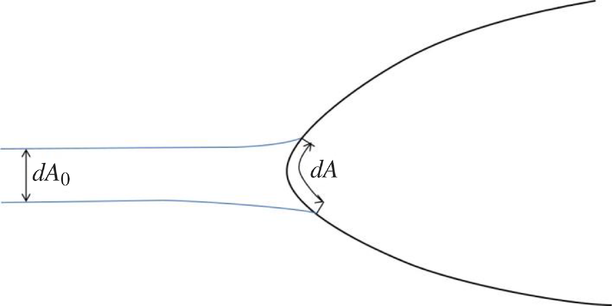
Figure 1. The schematic of droplet impingement onto the wing.
2.3 Film flow simulation
The thin water film on the wing surface is formed by the impingement of droplets and flows downstream driven by gravity and air shear force. The thin film (with a thickness less than 0.1mm) is assumed to be laminar. The thin film flow model is based on the thin-film assumption [Reference Meredith, Xin and Vries33]: 1) pressure in the normal direction is constant; 2) normal gradients are considered other than the much smaller tangential gradients; 3) tangential velocity is considered other than the much smaller normal velocity.
2.3.1 Mass continuity equation
The continuity equation of film flow is:
where h is the thickness of water film,
![]() ${\rho _l}$
is the density of the liquid film, average velocity of water film flow is,
${\rho _l}$
is the density of the liquid film, average velocity of water film flow is,
![]() $\frac{{\sum {{m_{\rm{d}}}} }}{{dtdS}}$
is defined as the mass change of the water film per unit area and per unit time, due to droplet impingement and splash. The splashing model is proposed by Bai [Reference Bai, Rusche and Gosman18].
$\frac{{\sum {{m_{\rm{d}}}} }}{{dtdS}}$
is defined as the mass change of the water film per unit area and per unit time, due to droplet impingement and splash. The splashing model is proposed by Bai [Reference Bai, Rusche and Gosman18].
2.3.2 Momentum transport equation
The momentum equation is:
where
![]() ${\nabla _{\rm{s}}}$
is the vector differential operator tangential to the surface,
g
s represents the tangential component of gravity acceleration,
${\nabla _{\rm{s}}}$
is the vector differential operator tangential to the surface,
g
s represents the tangential component of gravity acceleration,
![]() $\frac{{\sum {{m_{\rm{d}}}{{{\boldsymbol{U}}}_{{\rm{d}},{\rm{s}}}}} }}{{dtdS}}$
is the tangential momentum change of water film per unit area and per unit time, and
$\frac{{\sum {{m_{\rm{d}}}{{{\boldsymbol{U}}}_{{\rm{d}},{\rm{s}}}}} }}{{dtdS}}$
is the tangential momentum change of water film per unit area and per unit time, and
![]() ${{{\boldsymbol{U}}}_{{\rm{d}},{\rm{s}}}}$
is the tangential velocity of droplets. The velocity profile in the normal direction is assumed quadratic, then we can get the correlation relationship of
${{{\boldsymbol{U}}}_{{\rm{d}},{\rm{s}}}}$
is the tangential velocity of droplets. The velocity profile in the normal direction is assumed quadratic, then we can get the correlation relationship of
![]() $\overline {{{{\boldsymbol{U}}}_l}{{{\boldsymbol{U}}}_l}} $
in convection term:
$\overline {{{{\boldsymbol{U}}}_l}{{{\boldsymbol{U}}}_l}} $
in convection term:
The pressure of the liquid film is:
where
![]() ${p_{\rm{a}}}$
is the air pressure, and the pressure caused by surface tension is:
${p_{\rm{a}}}$
is the air pressure, and the pressure caused by surface tension is:
The hydrostatic pressure is
where n is the unit normal vector, and the normal dynamic pressure arising from impingement and splash is:
where
![]() ${{{\boldsymbol{U}}}_{{\rm{d}},{\rm{n}}}}$
is the normal velocity of droplets. The film-gas interface shear stress
${{{\boldsymbol{U}}}_{{\rm{d}},{\rm{n}}}}$
is the normal velocity of droplets. The film-gas interface shear stress
![]() ${{\boldsymbol{\tau }}_{\rm{f}}}$
and the film-wall interface shear stress
${{\boldsymbol{\tau }}_{\rm{f}}}$
and the film-wall interface shear stress
![]() ${{\boldsymbol{\tau }}_{\rm{w}}}$
are, respectively:
${{\boldsymbol{\tau }}_{\rm{w}}}$
are, respectively:
where the film-gas interface shear
![]() ${{\boldsymbol{\tau }}_{\rm{f}}}$
can be got from the air flow field solver.
${{\boldsymbol{\tau }}_{\rm{f}}}$
can be got from the air flow field solver.

Figure 2. The solution procedure of droplet impingement and film flow using OpenFOAM.
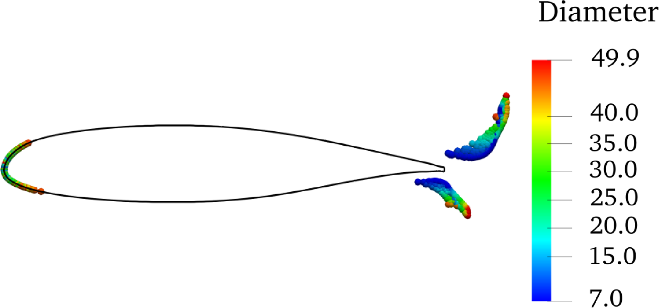
Figure 3. The impingement of droplets onto 2D MS-0317 aerofoil and the contours of droplet dimeters (with unit μm), with free stream velocity of 78.66m/s and MVD of 16μm.
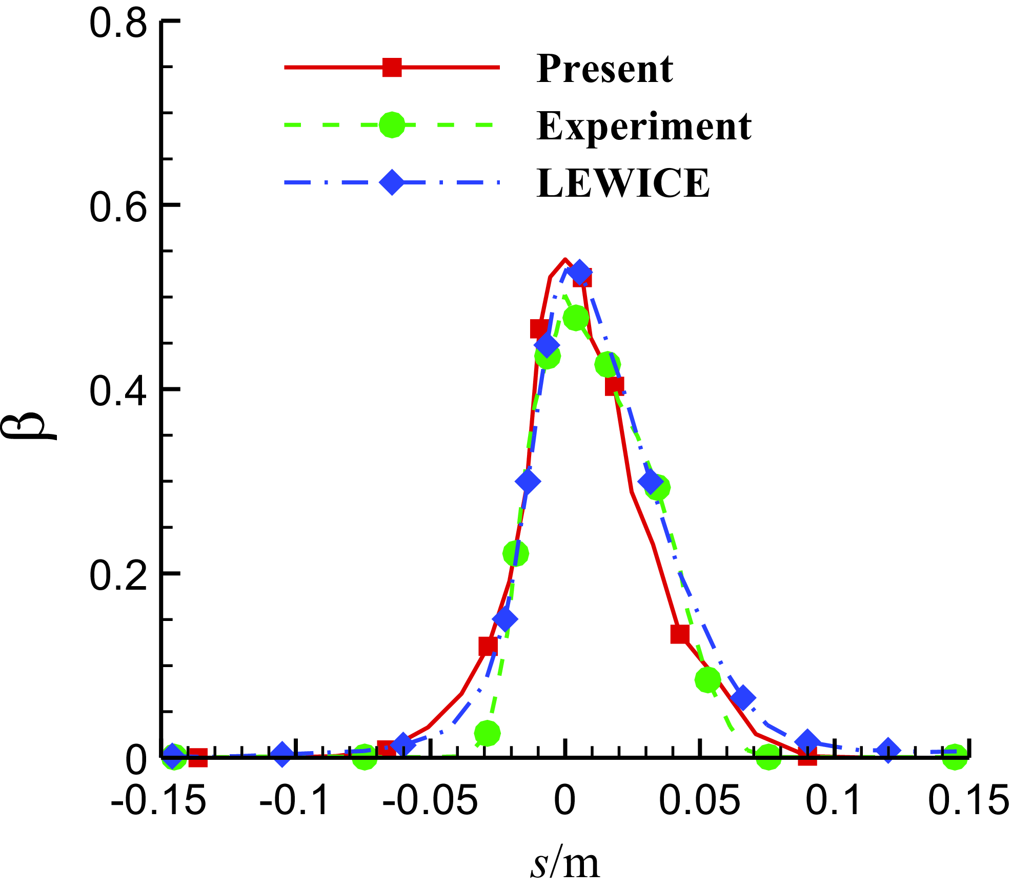
Figure 4. Comparison of the local water collection efficiency of 2D MS-0317 aerofoil with free stream velocity of 78.66m/s and MVD of 16μm.
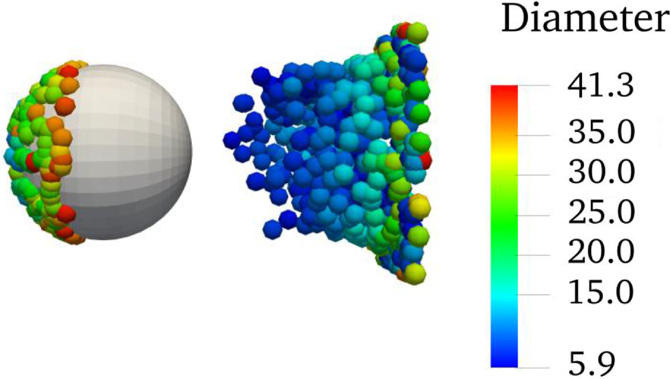
Figure 5. The impingement of droplets onto 15.04cm diameter sphere and the contours of droplet dimeters (with unit μm), with free stream velocity of 75m/s and MVD of 18.6μm.
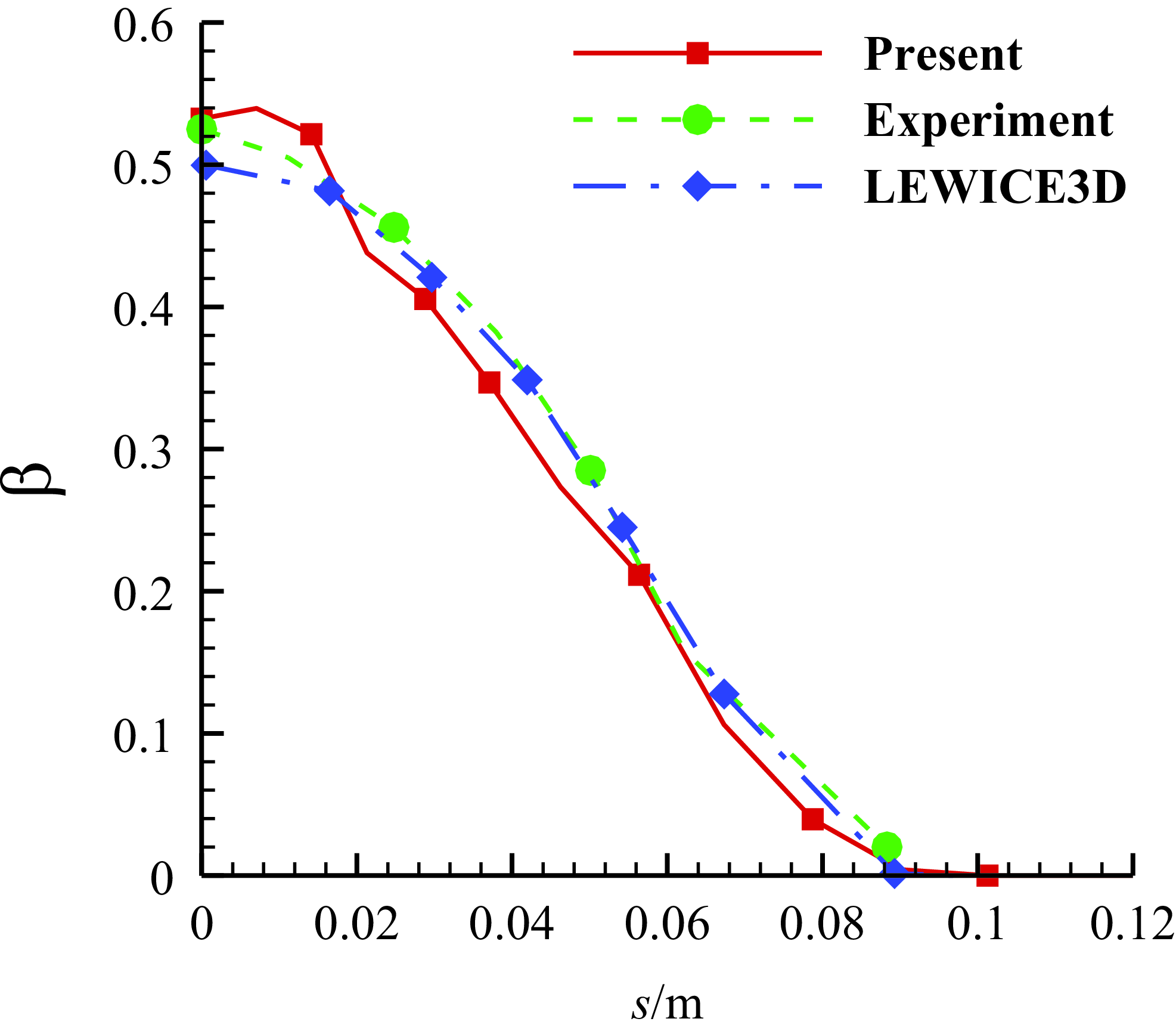
Figure 6. Comparison of the local water collection efficiency of 15.04 cm diameter sphere with free stream velocity of 75m/s and MVD of 18.6μm.
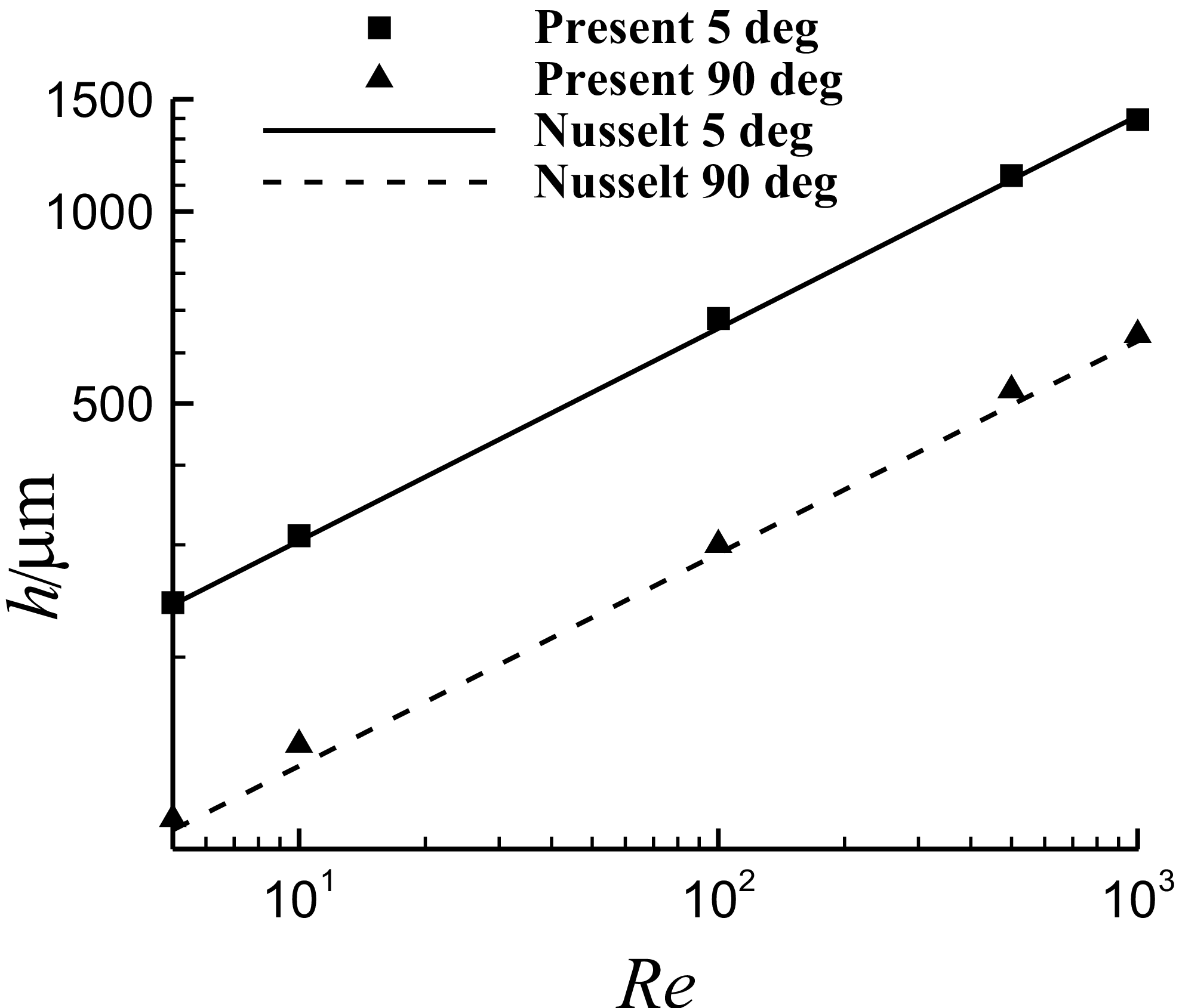
Figure 7. Comparison of the film thickness with Nusselt solution for steady continuous water film flow over a plane with inclined angles of 5° and 90°.
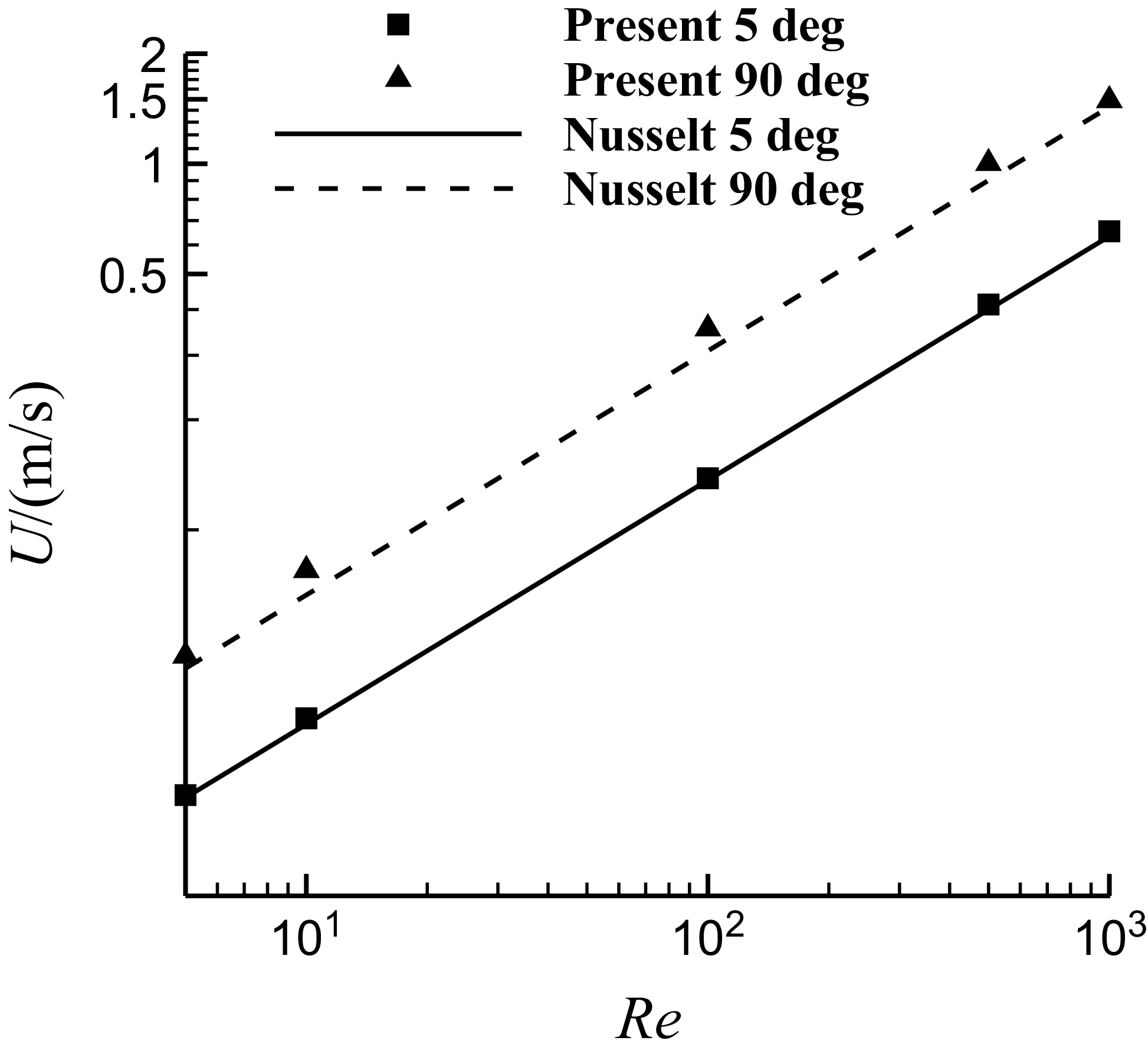
Figure 8. Comparison of the film velocity with Nusselt solution for steady continuous water film flow over a plane with inclined angles of 5° and 90°.

Figure 9. Comparison of the pressure coefficient contours of three grids with different cell numbers with free stream velocity of 67m/s and AOA of 0°. (a) The pressure coefficient contours on the symmetry and wall surfaces of the grid with 277,000 cells. (b) The pressure coefficient contours on the symmetry and wall surfaces of the grid with 602,000 cells. (c) The pressure coefficient contours on the symmetry and wall surfaces of the grid with 897,000 cells.
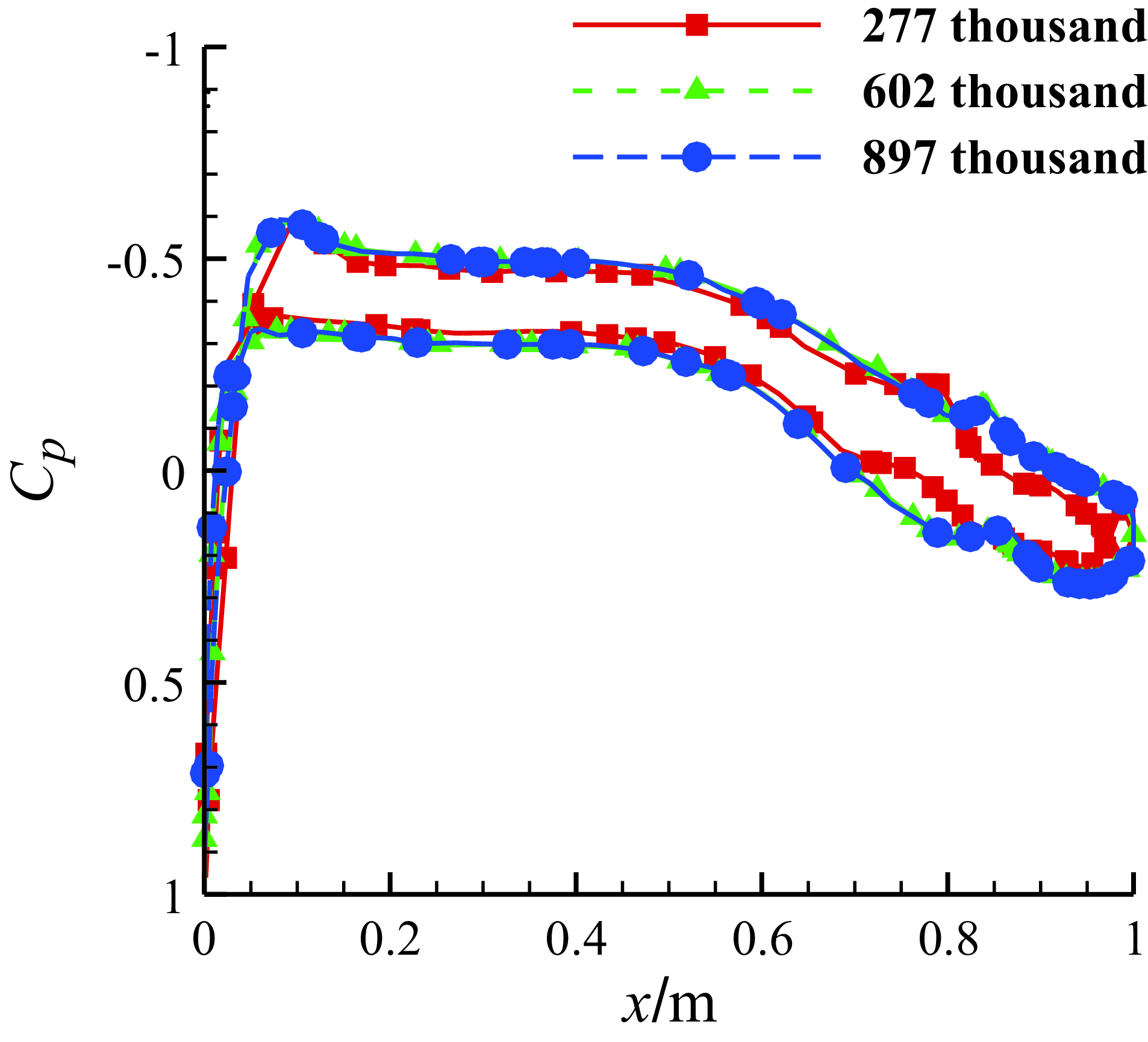
Figure 10. Comparison of the pressure coefficient distributions on the middle section of the half-wing of three grids with different cell numbers with free stream velocity of 67m/s and AOA of 0°.
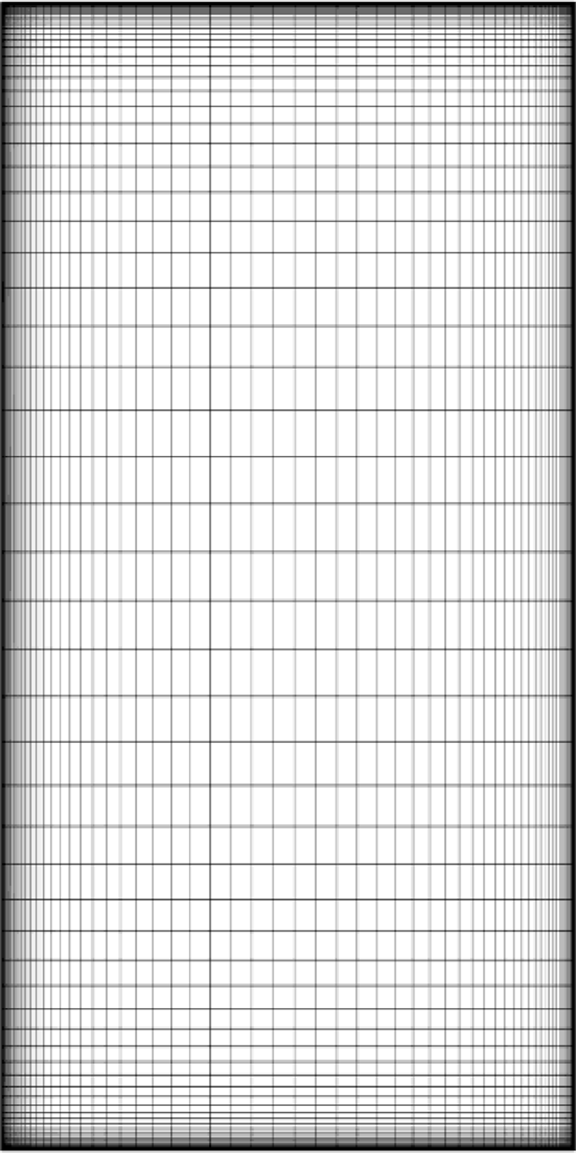
Figure 11. The surface mesh of MS-0317 straight wing, composed of quadrilateral faces.
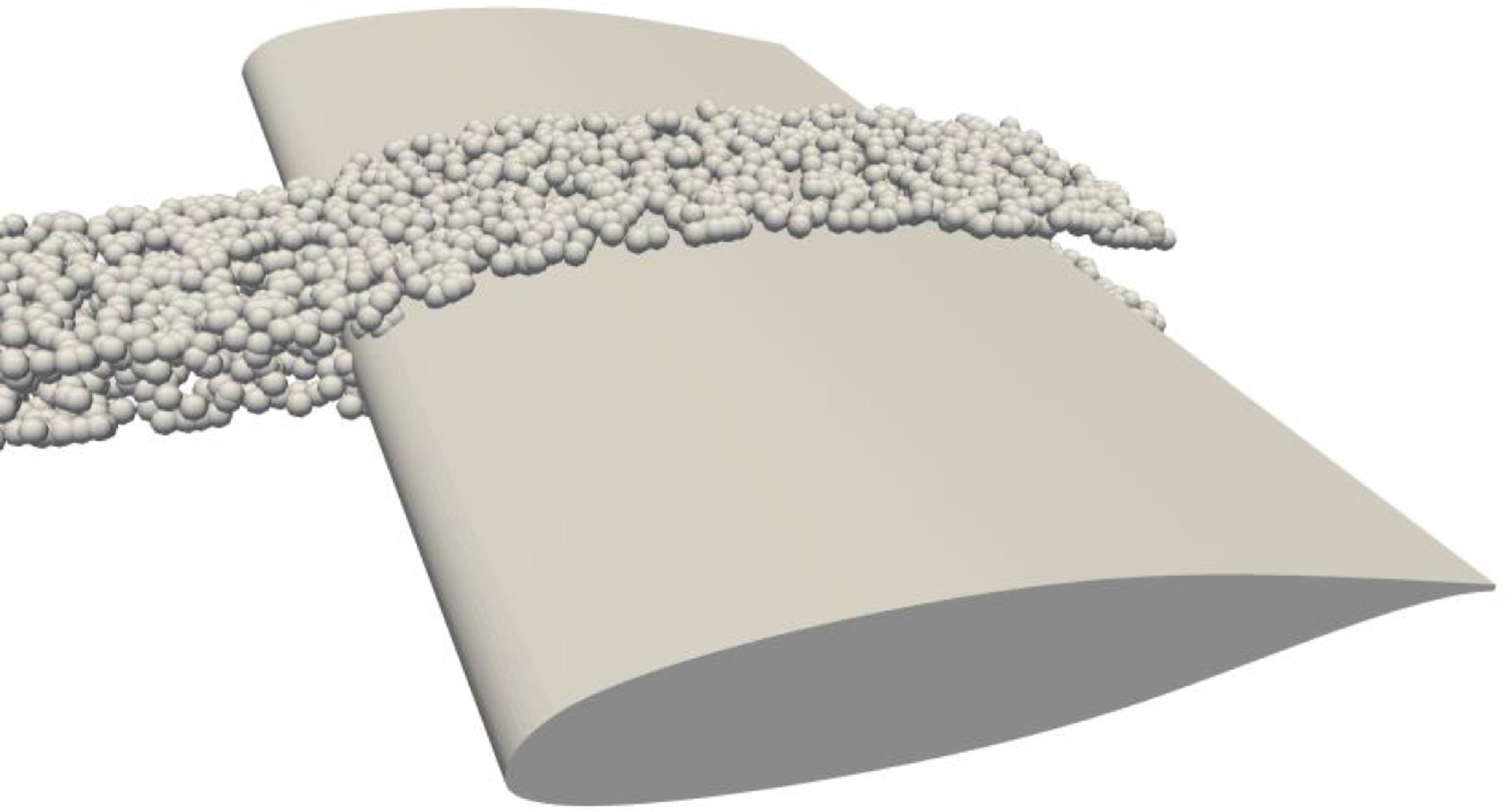
Figure 12. The droplets movement around three-dimensional MS-0317 straight wing, covering the region near the spanwise midpoint of the half wing.
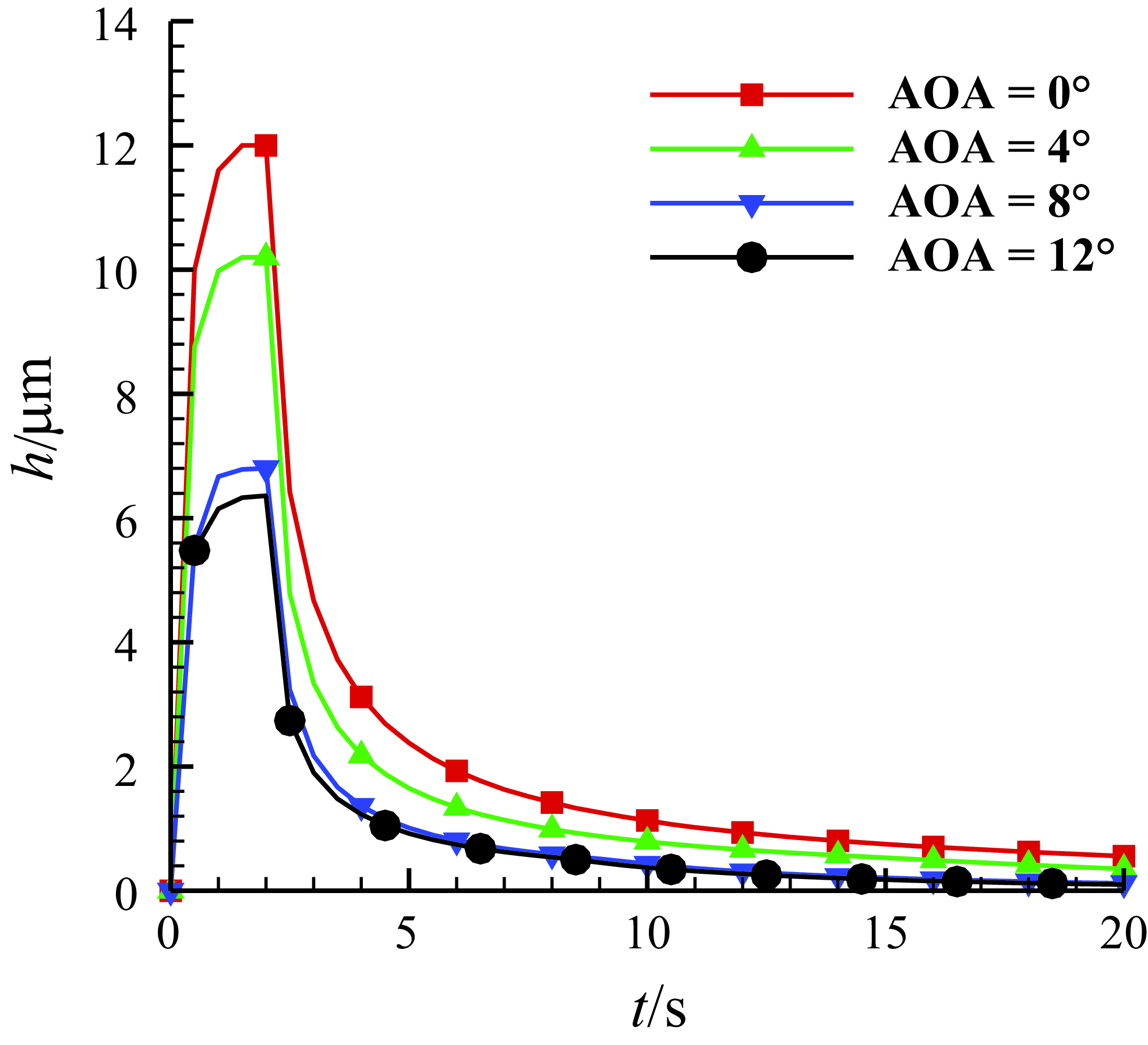
Figure 13. The time history of the water film thickness at the leading-edge point of three-dimensional MS-0317 straight wing in 20s, with AOA of 0°, 4°, 8° and 12°, free stream velocity of 67m/s, LWC of 1.03g/m3 and MVD of 18.6μm.
The film flow control equations are solved using the Finite Area Method (FAM) [Reference Tuković26], which is suitable for solving partial differential equations on curved surfaces. In OpenFOAM, FAM is implemented on a two-dimensional surface mesh that is tangential to the wing surface. The mesh is only one layer normal to the surface and is extruded from the wing boundary mesh. This approach separates the film flow from the air flow, making it more resource efficient than the interface capture method.
2.4 Interaction of the air flow, droplet movement and thin water film flow
The computational process of droplet impingement and film flow is illustrated in Fig. 2. It is considered as a one-way coupling between air flow and droplet movement: the air flow influences the trajectories of the droplets, while the effects of the droplets on the variables of the air flow are negligible. A one-way coupling is also assumed between air flow and water film flow: the air flow shear force drives the water film to flow downstream, without considering the influence of the water film on the air flow. It is considered to be a two-way coupling between droplet movement and film flow: the impingement of droplets onto water film changes the mass and momentum of the water film, while the droplets from the splash return to the air and are tracked again. In OpenFOAM, both droplet movement and water film flow can be simulated using reactingParcelFoam.
3.0 Validation
The computation of the local collection efficiency of a two-dimensional MS-0317 aerofoil and a three-dimensional sphere is used to validate the computation of droplet movement and impingement. Then, the film flow computational model is verified with the theoretical solution.
3.1 Local collection efficiency
To validate the computation of droplet movement and impingement, the local collection efficiency of a two-dimensional MS-0317 aerofoil and a three-dimensional sphere is calculated and compared with the data from experiments and LEWICE.
3.1.1 Two-dimensional MS-0317 aerofoil
The chord of MS-0317 aerofoil is 0.914m, the environmental pressure is 101216 Pa, the temperature is 291.046K, the air flow velocity is 78.66m/s, AOA = 0°, and the liquid water content (LWC) is 0.19g/m3. The median volumetric diameter (MVD) is 21μm. The droplet diameters are subjected to Rosin-Rammler distribution.
Figure 3 displays the process of droplets impinging on the aerofoil as well as the contours of droplet diameters. Figure 4 is the comparison of the present computed local water collection efficiency with the experiment and LEWICE [Reference Papadakis, Hung and Vu34]. It is seen that the computation results of the collection efficiency match well, so the computation result of the droplets movement is reasonable.
3.1.2 Sphere
The diameter of the sphere is 15.04cm. The ambient pressure is 95840Pa, the flow velocity is 75m/s, air density is 1.097kg/m3, MVD of droplets is 18.6μm, and the Rosin-Rammler distribution is used for droplet diameters.
Figure 5 shows the impingement process of the droplets onto the three-dimensional sphere. The collection efficiency is compared with the experimental data and LEWICE3D simulation results [Reference Bidwell and Mohler35] in Fig. 6, which shows a good match. It means the computation of the droplet movement fits the three-dimensional cases.
3.2 Nusselt solution for film flow
In this section, the Nusselt solution [Reference Nusselt36] is used to verify the thin film flow model. The film thickness and velocity of steady continuous water film flow over a plane with two inclined angles (5° and 90°) are computed and compared with Nusselt solution respectively. The temperature is 298K.
The thickness and velocity of the Nusselt solution have the theoretical correlations with Reynold number respectively as shown below. Comparisons of solution in the present numerical simulation with that of the theoretical Nusselt solution are shown in logarithmic scale in Figs. 7 and 8, which show good agreement.
where
![]() $\theta $
is the inclined angle.
$\theta $
is the inclined angle.
4.0 Film flow of three-dimensional MS-0317 wing
To investigate the three-dimensional effects on the flow characteristics of the thin water film of three-dimensional wings, a numerical simulation is performed to study the droplet impact and film flow on the MS-0317 wing.
4.1 Grid independence study
Firstly, for the three-dimensional wing, we use three grids of different cell numbers to investigate the grid independence, with cell numbers of 277,000, 602,000 and 897,000. The three-dimensional wing is obtained by straight extrusion of the MS-0317 aerofoil in the spanwise direction, and the semispan is 1.8288m. The flow velocity is 67m/s, AOA = 0°. Figure 9 shows the pressure coefficient contours on the symmetry and wall surfaces of three grids with 277,000, 602,000 and 897,000, and Fig. 10 is the comparison of the pressure coefficient distributions on the middle section of the half-wing of the three grids. We can see that both the pressure coefficient contours and the distributions of the two grids with 602,000 and 897,000 cells are almost the same. The grid with 602,000, cells is therefore suitable. Figure 11 shows the wing surface mesh of the grid with 602,000 cells.
4.2 Three-dimensional MS-0317 straight wing with different AOAs
The characteristics of the film flow with AOA = 0°, 4°, 8° and 12° are evaluated and compared, respectively. The flow velocity is 67m/s, LWC = 1.03g/m3, MVD = 20μm, and the temperature is 300K. Here the region near the spanwise midpoint of half wing (0.7144m ∼ 1.1144m) is covered by the droplets, as shown in Fig. 12. Without covering the entire wing, firstly the computation cost is reduced greatly, and secondly enough interesting information can be acquired with this region.
Table 1. The maximum value of the film thicknesses with AOA of 0°, 4°, 8° and 12° at the leading-edge point of the spanwise middle section of half wing

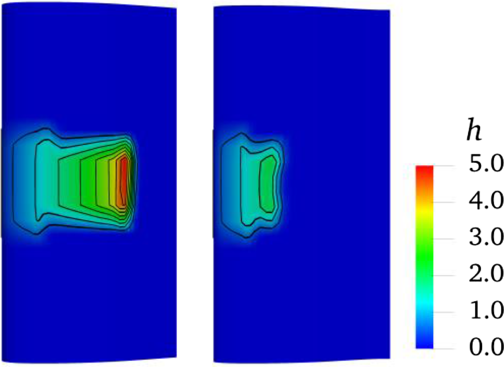
Figure 14. The thickness distribution (with unit μm) of the water film on upper surface (left, wing root on top) and lower surface (right, wing tip on top) of the three-dimensional MS-0317 straight wing at 20s, with AOA of 0°, free stream velocity of 67m/s, LWC of 1.03g/m3 and MVD of 18.6μm.
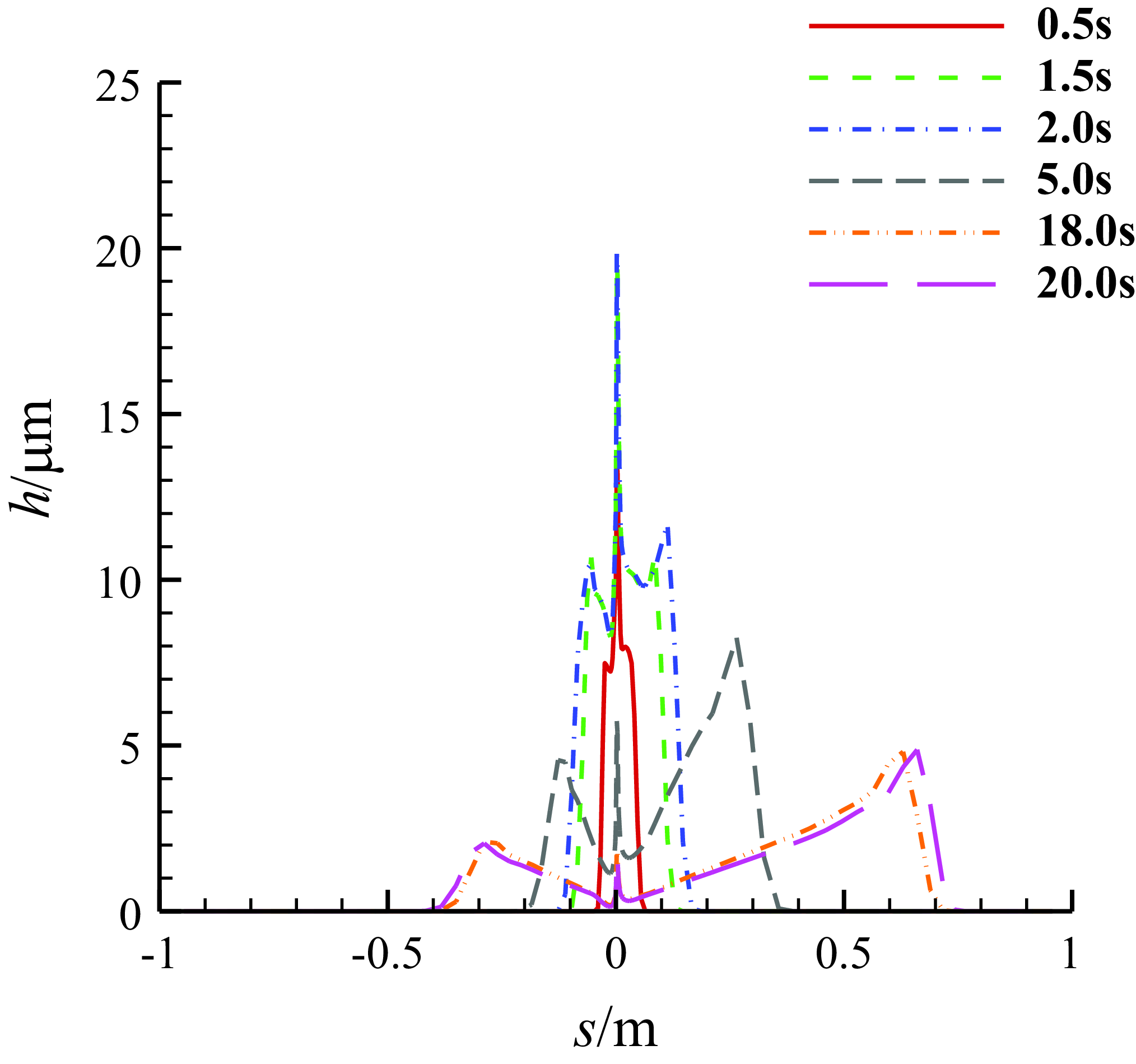
Figure 15. The thickness distributions of the water film on the middle section of three-dimensional MS-0317 straight wing at different time, with AOA of 0°, free stream velocity of 67m/s, LWC of 1.03g/m3 and MVD of 18.6μm.
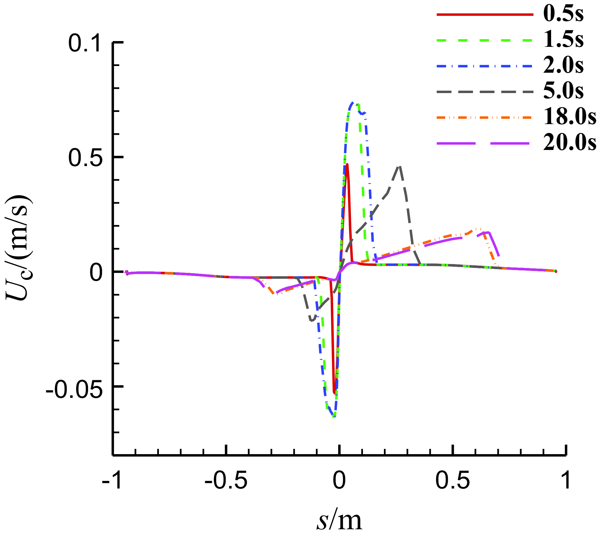
Figure 16. The chordwise velocity distributions of the water film on the middle section of MS-0317 straight wing at different time, with AOA of 0°, free stream velocity of 67m/s, LWC of 1.03g/m3 and MVD of 18.6μm.
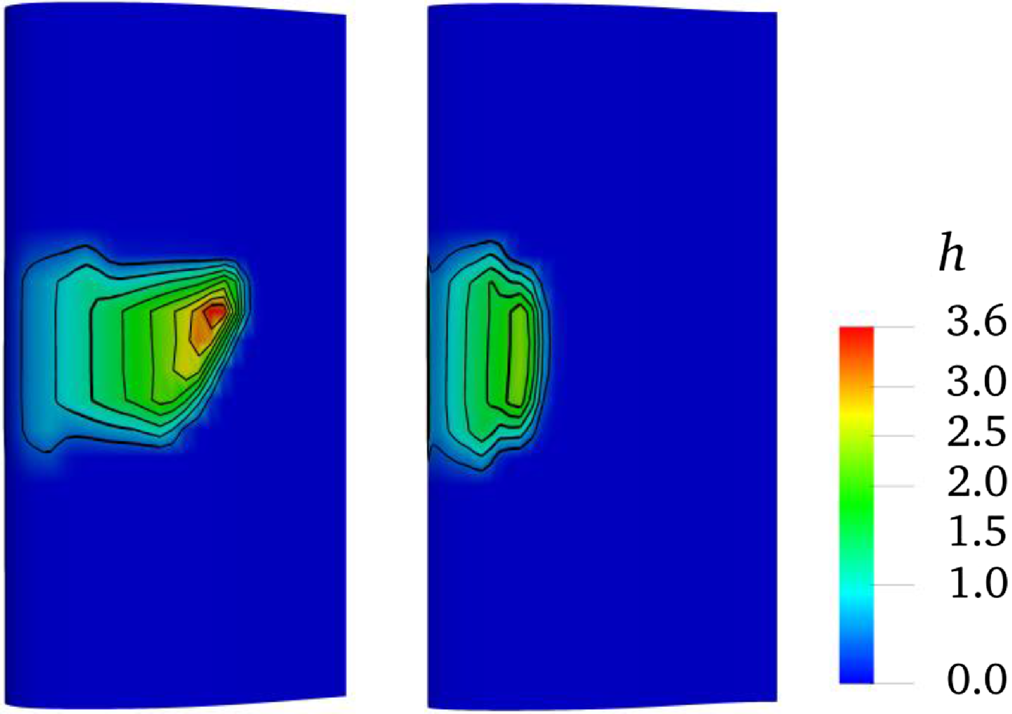
Figure 17. The thickness distribution (with unit μm) of the water film on upper surface (left, wing root on top) and lower surface (right, wing tip on top) of three-dimensional MS-0317 straight wing at 20s, with AOA of 8°, free stream velocity of 67m/s, LWC of 1.03g/m3 and MVD of 18.6μm.
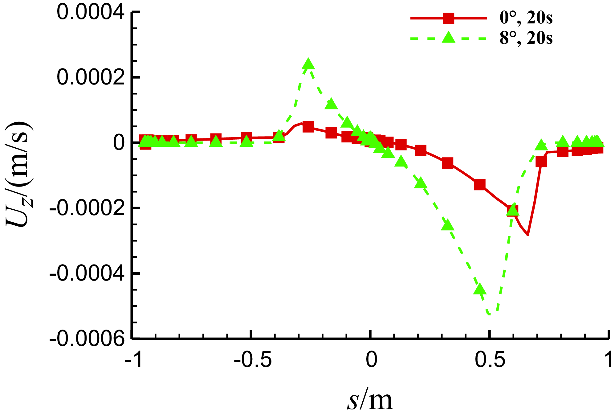
Figure 18. Comparison of the spanwise velocity of the water film on the middle section of three-dimensional MS-0317 straight wing with different AOAs at 20s, with the same free stream velocity of 67m/s, LWC of 1.03g/m3 and MVD of 18.6μm.
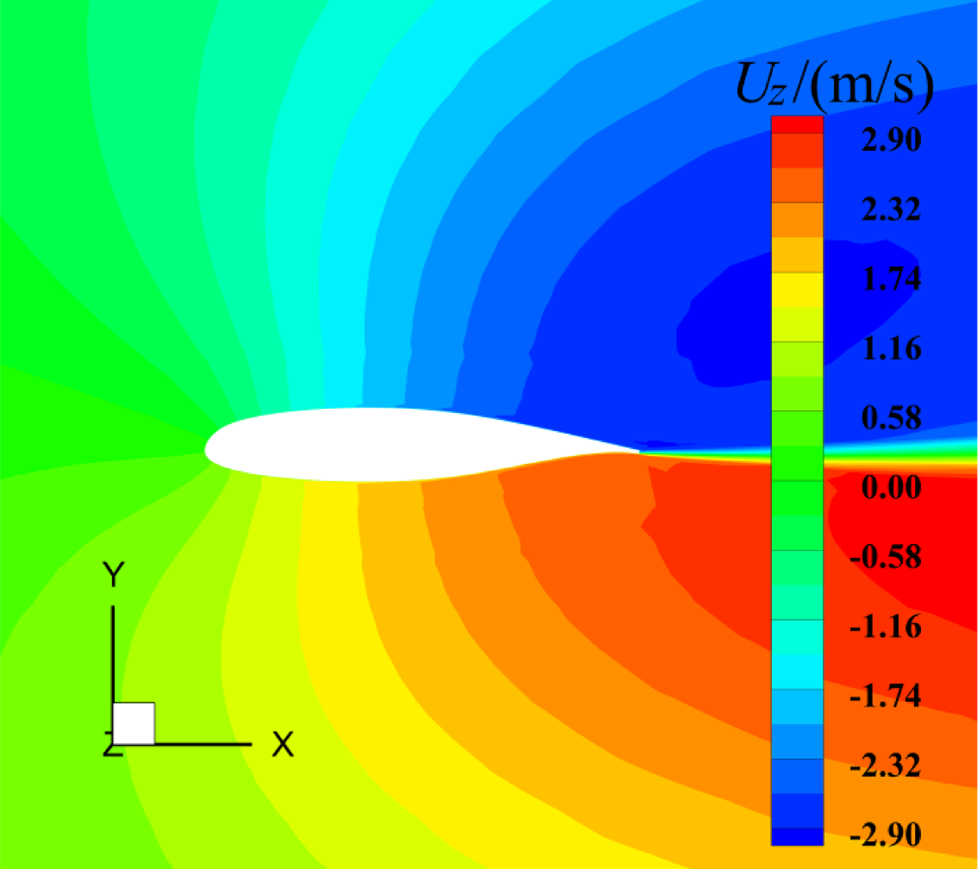
Figure 19. The spanwise flow velocity of the air near the middle surface of three-dimensional MS-0317 straight wing, with AOA = 8°, free stream velocity of 67m/s.
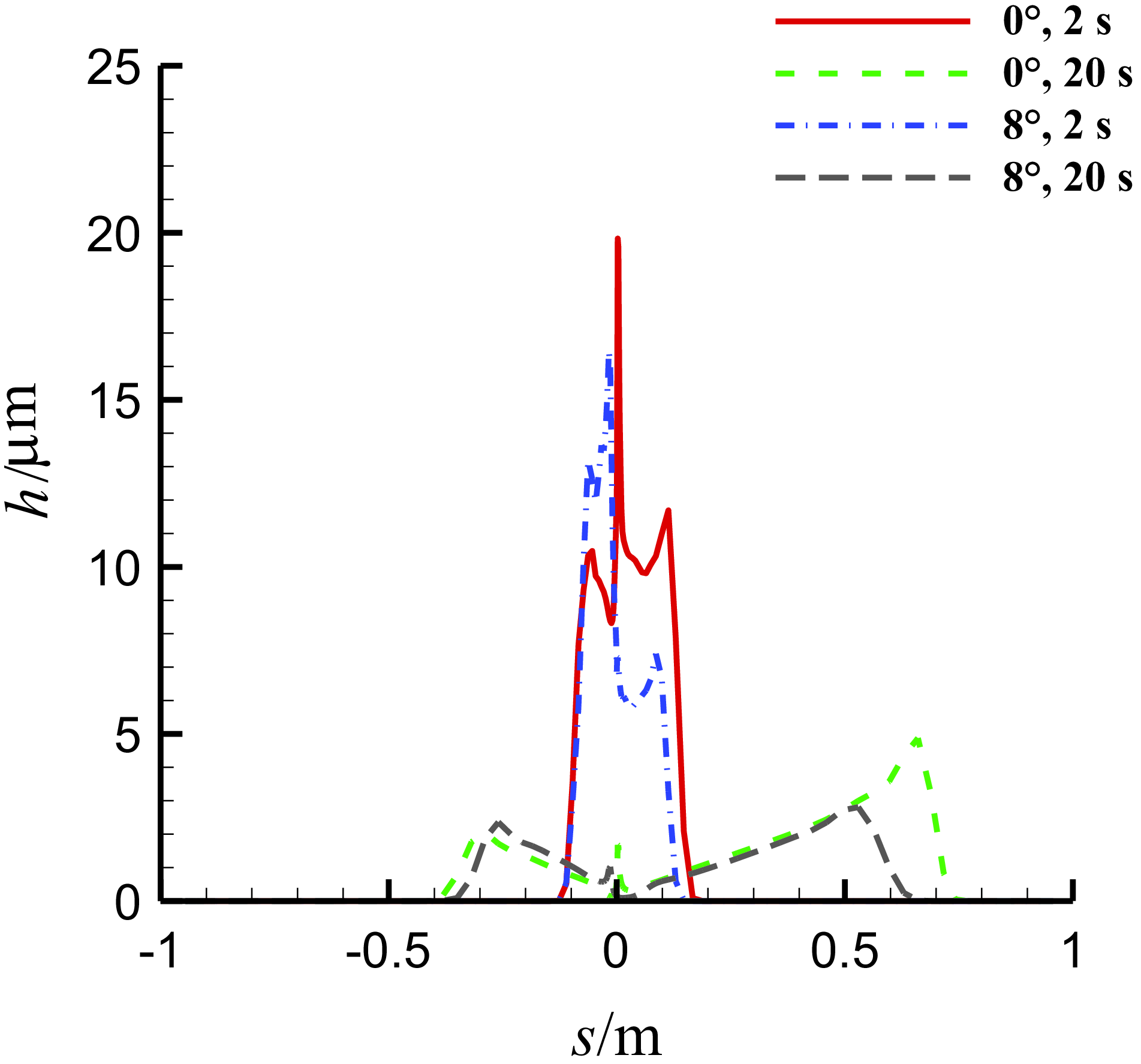
Figure 20. Comparison of the thickness of the water film on the middle section of three-dimensional MS-0317 straight wing at different time, with different AOAs, with the same free stream velocity of 67m/s, LWC of 1.03g/m3 and MVD of 18.6μm.
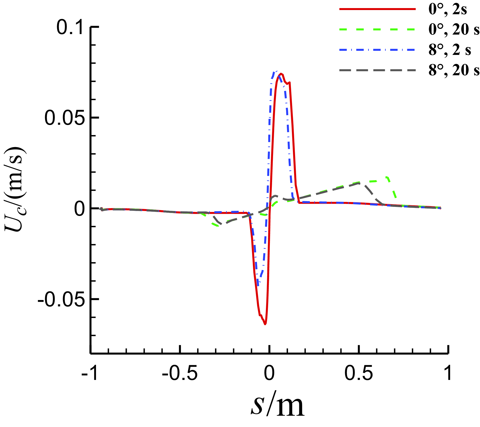
Figure 21. Comparison of the chordwise velocity of the water film on the middle section of three-dimensional MS-0317 straight wing at different time, with different AOAs, with the same free stream velocity of 67m/s, LWC of 1.03g/m3 and MVD of 18.6μm.
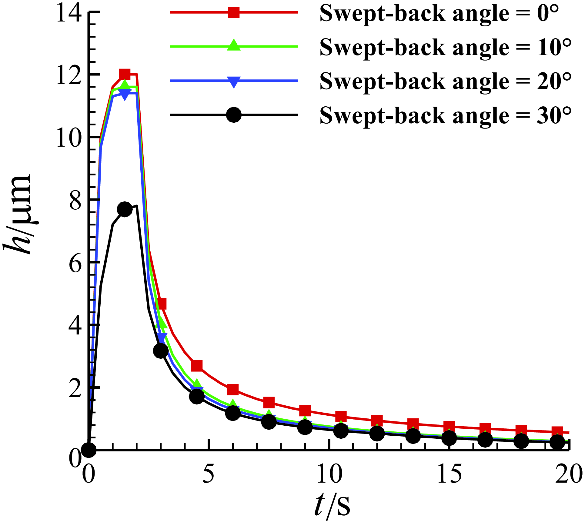
Figure 22. The time history of the water film thickness at the leading-edge point of MS-0317 swept wing in 20s, with swept-back angle of 0°, 10°, 20° and 30°, AOA of 0°, free stream velocity of 67m/s, LWC of 1.03g/m3 and MVD of 18.6μm.
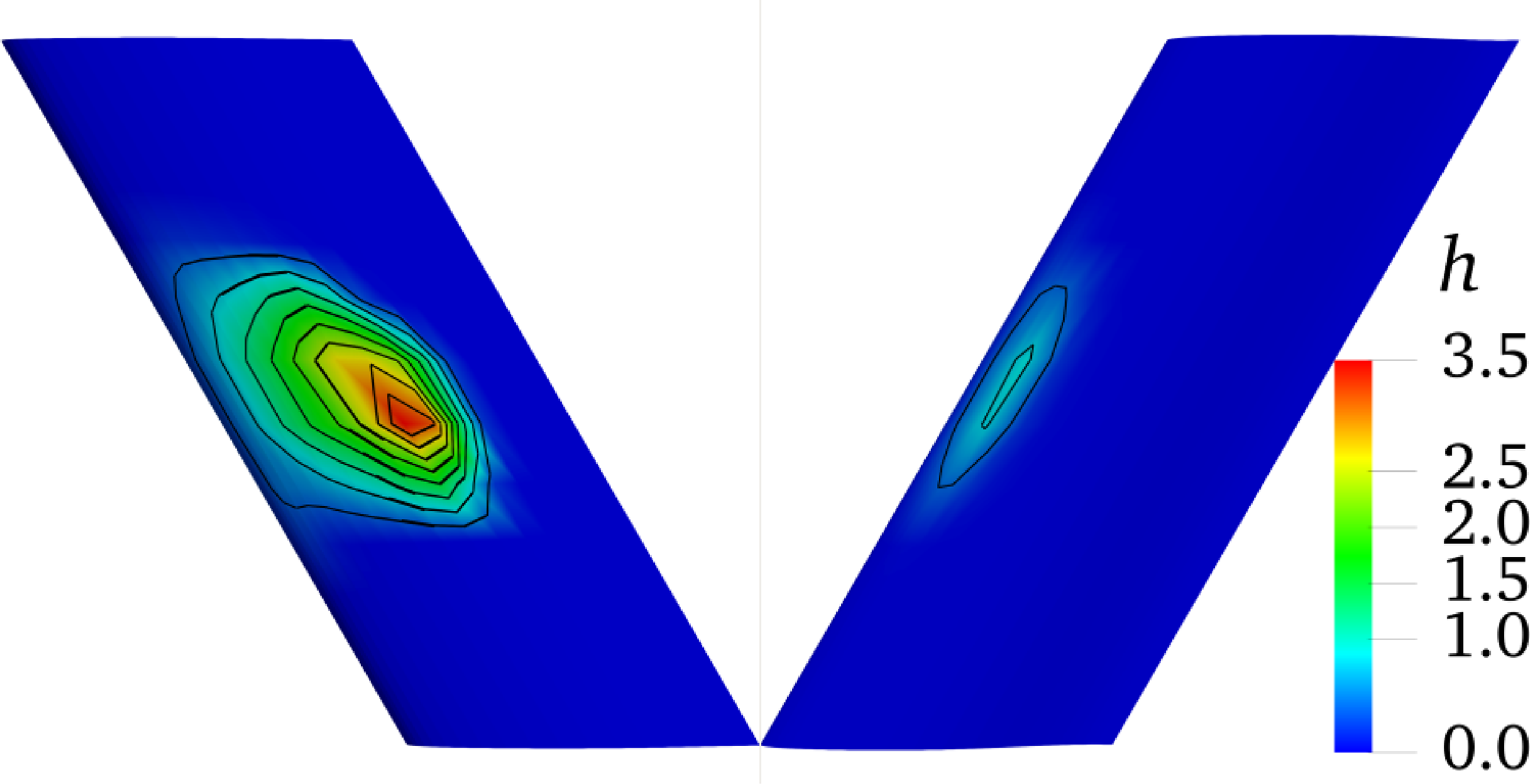
Figure 23. The thickness distribution (with unit μm) of the water film on upper surface (left, wing root on top) and lower surface (right, wing tip on top) of three-dimensional MS-0317 swept wing (swept-back angle = 30°) at 20s, with AOA of 0°, free stream velocity of 67m/s, LWC of 1.03g/m3 and MVD of 18.6μm.
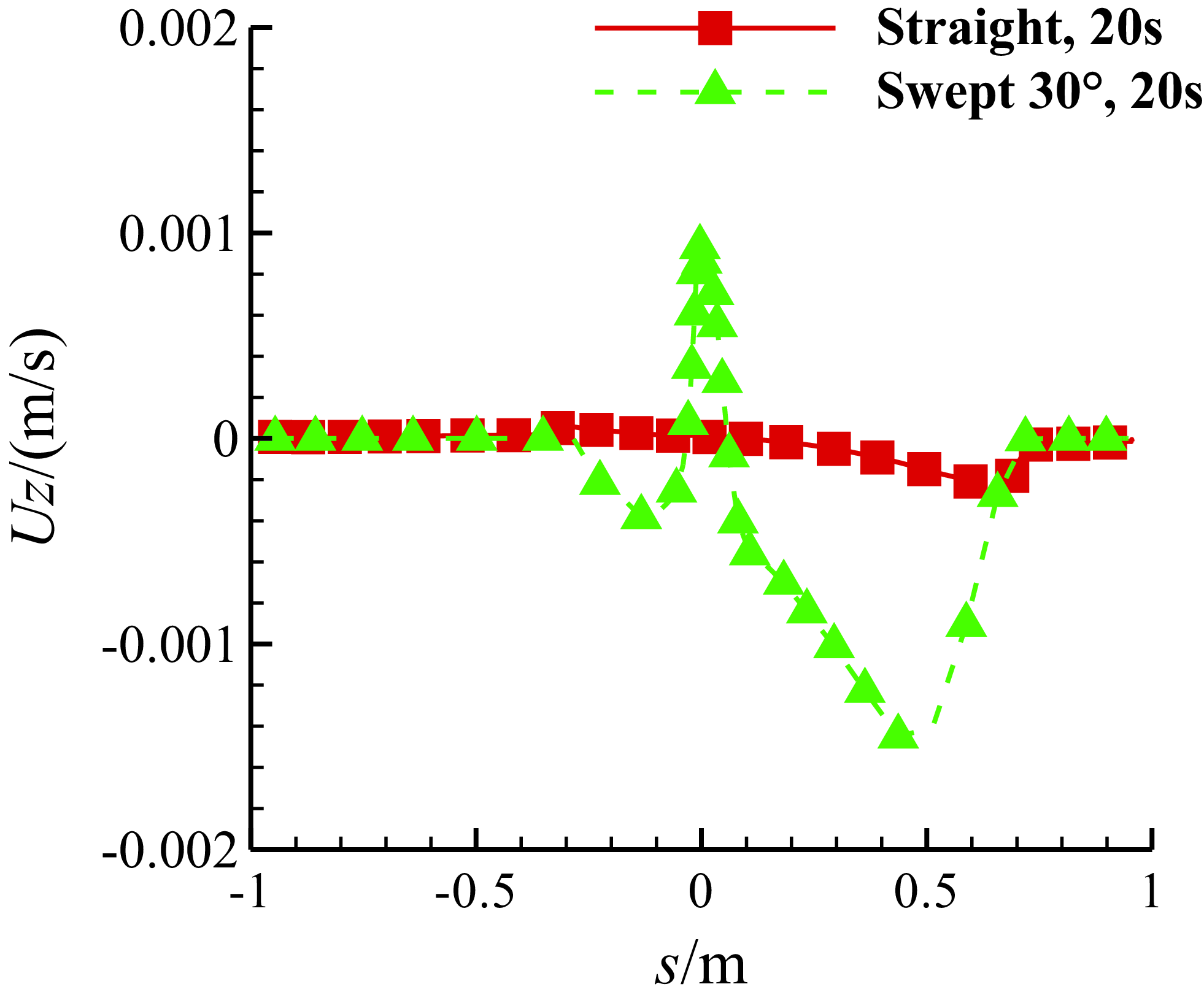
Figure 24. Comparison of the spanwise velocity of the water film on the middle section of MS-0317 straight and swept wing (swept-back angle = 30°) at 20s, with AOA of 0°, free stream velocity of 67m/s, LWC of 1.03g/m3 and MVD of 18.6μm.
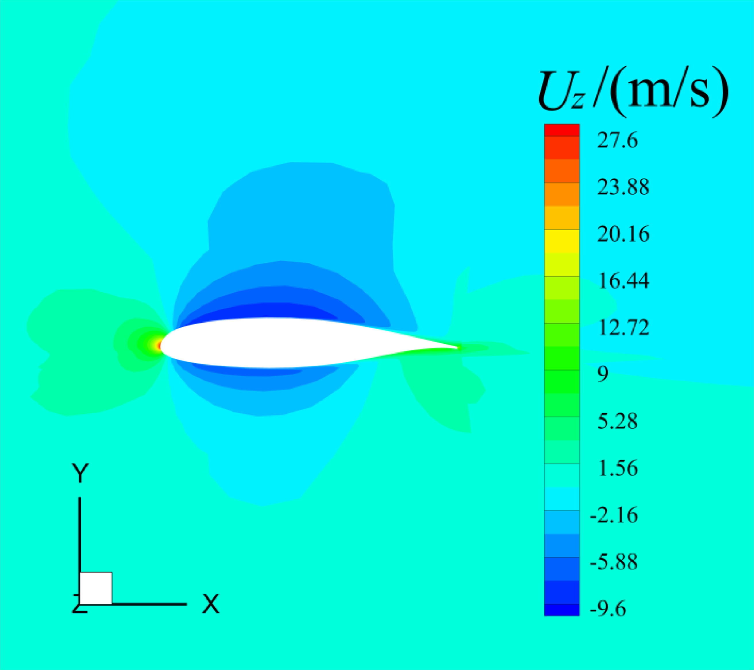
Figure 25. The spanwise flow velocity of the air near the middle surface of three-dimensional MS-0317 swept wing (swept-back angle = 30°), with AOA = 0°, free stream velocity of 67m/s.
In all simulations, the total computation time is 20s, while the injection duration of droplets is 2s from the start. Figure 13 is the time history of the water film thickness at the leading-edge point of the spanwise middle section of half wing with AOA of 0°, 4°, 8° and 12°. We can see that the thickness gets to the maximum and keeps constant during the injection of the droplets and then the thickness reduces affected by the air shear force once the injection stops but seems to be nonzero at last, and the values eventually converge to the same. This is because during the injection, the transport mass of the thin film flow will equal to the mass added by the droplet impingement in the end, and without injection, the wall shear force eventually gets to equilibrium with the air shear force. As the AOA increases, the water film thickness gradually decreases. The value of the maximum thicknesses with AOA of 0°, 4°, 8° and 12° are shown in Table 1. Although the maximum thicknesses are different, both the history curves of the water film thickness before and after the end of the injection at the leading-edge point can be fitted with logarithmic functions. The following is a detailed study of the water film flow characteristics with AOA = 0° and 8°.
4.2.1 AOA = 0°
Figure 14 is the thickness distribution of the water film on upper surface (left) and lower surface (right) of the MS-0317 straight wing at 20s. It is seen that there is more water on the upper surface than that on the lower surface and the water film distribution is almost symmetric to the centreline of the wing span. On the middle section of the MS-0317 straight wing, the thickness of the water film along the surface distance at different time (0.5s, 1.5s, 2s, 5s, 18s and 20s) are shown in Fig. 15. We can see that before 2s, the thickness at the leading edge increases to the maximum and retains constant, meanwhile the coverage of the film gets larger, but after 2s, the thickness at the leading edge reduces, however the coverage of the film still gets larger due to the driven effects of the air flow. The final water film thickness is consistent with the glaze ice shapes.
Figure 16 is the chord-wise velocity of the water film along the surface distance of the middle section of the MS-0317 straight wing at different time (0.5s, 1.5s, 2s, 5s, 18s and 20s). In this coordinate system, the velocity of the water film is negative on the lower surface but positive on the upper surface. We can see that the velocity of the film near the leading-edge point is zero, firstly the velocity increases downstream on the both sides and then reduces to zero. Where the film thickness is large, the velocity is large, too.
4.2.2 AOA = 8°
Figure 17 is the thickness distribution of the water film on upper surface (left) and lower surface (right) of the MS-0317 straight wing at 20s. The thickness distribution is apparently asymmetric particularly on the upper surface.
Then let us see the comparison of the spanwise velocity of the water film on the middle section with AOA = 0° and 8° at 20s in Fig. 18. The water film flows outward in the spanwise direction on the lower surface but inward on the upper surface, and with the larger AOA, the spanwise velocity of the water film becomes larger. The spanwise flow of the water film is caused from the spanwise shear force of the air flow, which arises from the three-dimensional effects of the finite-span wing. When AOA = 8°, the outward flow velocity of the air under the lower surface and the inward flow velocity above the upper surface are both obvious, as shown in Fig. 19.
Figure 20 is the comparison of the thickness of the water film on the middle section with different AOAs at different time. The thickness on the lower surface with AOA = 8° is larger than that with AOA = 0°, however the thickness on the upper surface with AOA = 8° is smaller than that with AOA = 0°, which is rational. Figure 21 is the comparison of the chordwise velocity of the water film on the middle section with different AOAs.
4.3 MS-0317 swept wings with different swept-back angles
For the MS-0317 swept wing, the characteristics of the film flow with swept-back angle = 0°, 10°, 20° and 30° are studied. All the conditions are the same with the first case “AOA = 0°”. Figure 22 is the time history of the water film thickness at the leading-edge point of the spanwise middle section of half wing with swept-back angle of 0°, 4°, 8° and 12°. As the swept-back angle increases, the water film thickness gradually decreases. The history curves of the water film thickness before and after the end of the injection at the leading-edge point can also be fitted with logarithmic functions.
Here is a detailed study of the water film flow characteristics with swept-back angle = 30°. Figure 23 is the thickness distribution of the water film on upper surface (left) and lower surface (right) of the MS-0317 swept wing at 20s. The thickness distribution is also asymmetric particularly on the upper surface, and the film on the upper surface flows outward as a whole.
The comparison of the spanwise velocity of the water film on the middle section between the MS-0317 straight and swept wing with swept-back angle = 30° is shown in Fig. 24. For the swept wing, the film flows outward near the leading edge, the spanwise velocity of the film firstly reduces downstream on the both sides to zero, then the film flows inward, the spanwise velocity increases to the maximum and finally reduces to zero.
The spanwise velocity is caused by the three-dimensional effects of the MS-0317 swept wing. The air velocity around the wing firstly slants to the wing tip, then to the wing root, and finally to the wing tip namely “S-type” streamlines due to the angle of sweepback. Figure 25 is the spanwise velocity around the middle section of the MS-0317 swept wing.
Figure 26 is the comparison of the thickness of the water film on the middle section between the MS-0317 straight and swept wing at different time. Because of the spanwise flow of the water film, we can see that the thickness of the MS-0317 swept wing is smaller than that of the straight one. Figure 27 is the comparison of the chordwise velocity of the water film between the MS-0317 straight and swept wing.
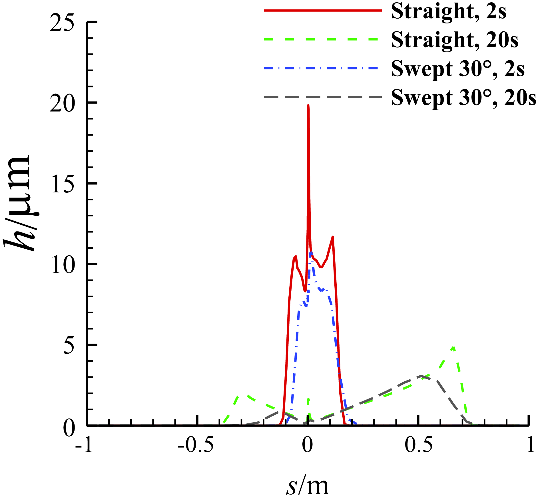
Figure 26. Comparison of the thickness of the water film on the middle section of the MS-0317 straight and swept wing (swept-back angle = 30°) at different time, with AOA of 0°, free stream velocity of 67m/s, LWC of 1.03g/m3 and MVD of 18.6μm.
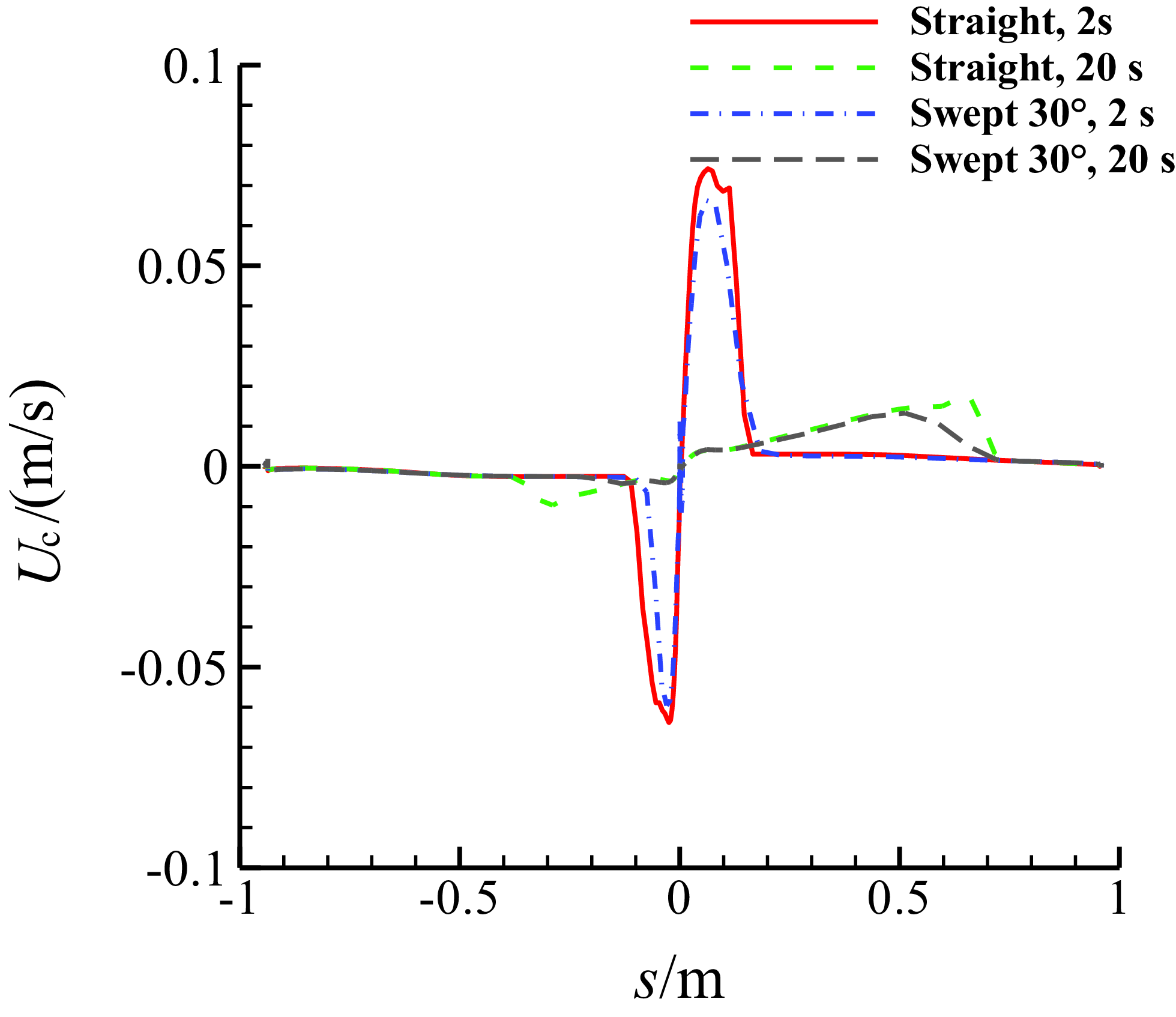
Figure 27. Comparison of the chordwise velocity of the water film on the middle section of MS-0317 straight and swept wing (swept-back angle = 30°) at different time, with the same AOA of 0°, free stream velocity of 67m/s, LWC of 1.03g/m3 and MVD of 18.6μm.
5.0 Conclusion
A numerical study was conducted based on OpenFOAM to investigate the droplet impingement and water film flow on the MS-0317 wing, with particular emphasis on the three-dimensional effects of angle-of-attack and sweepback angle. The air flow field analysis was carried out by solving the RANS equations using a k-ω-SST turbulence model. The movement and impingement of the droplets were evaluated using the Lagrangian method. The water film flow on the wing surface was simulated by combining the thin-film assumption with the finite area method. Coupling between the air flow, droplet movement and film flow was considered. The collection efficiency of the MS-0317 aerofoil and a sphere was compared with experiment to validate the computation of droplet movement and impingement. The comparison of the film flow of an inclined plane with theoretical Nusselt solution was performed, and good agreement was achieved. Finally, the numerical simulation of the film flow on the three-dimensional MS-0317 wing was carried out and analysed, and important conclusions were drawn as follows:
-
1) Different simplifications of the film flow have been adopted for the simulation of icing, but the effects of these simplifications on the accuracy of the results remain unclear. This paper examined the effects of the angle-of-attack and the angle of sweepback on the flow characteristics of the thin water film using thin-film assumption with a quadratic velocity profile, considering splashing effects. We found that the water film thickness before and after the end of the injection at the leading edge point increases and decreases with time as a logarithmic function.
-
2) When the angle-of-attack and sweepback are both zero, the three-dimensional effects are minimal, and the water film distribution is nearly symmetric. Because of the influence of the angle-of-attack and the angle of sweepback, significant three-dimensional effects are present, resulting in spanwise flow of the water film. On the lower surface, the water film flows outwards in the spanwise direction, while on the upper surface, it flows inwards due to AOA. Due to the sweepback angle, near the leading edge the film flow is outward, and the spanwise velocity of the film first decreases to zero downstream on both sides; then the film flow reverses and flows inward, causing the spanwise velocity to increase to its maximum value before decreasing to zero.
-
3) The three-dimensional effects of angle-of-attack and sweepback are significant on the flow of the unfrozen liquid film, making the influence of warm glaze ice with surface water film on three-dimensional ice accretion non-negligible. Therefore, more research should be carried out on the flow of the surface water film for the three-dimensional glaze ice shapes.
Acknowledgements
This work was supported by The Fundamental Research Funds for the Central Universities with grant number 3122019164.


