Introduction
With the continuous demand of the market, 4G has gradually failed to meet today’s communication needs and 5G came into being. Due to the scarcity of spectrum resources, the design of miniaturized, broadband, high-gain, and array antennas has become a hot topic of research today [Reference Xia1, Reference Alsulami2].
Circularly polarized (CP) antenna has the advantages of anti-Faraday rotation effect and anti-multipath interference. It can receive arbitrary line polarization signals and can avoid the mismatch problem caused by polarization mismatch. Therefore, the CP antenna can achieve stable communication transmission, and the CP antenna is needed in many wireless communication systems to transmit and receive signals [Reference Ran, Jin, Wang, Chen and Wu3, Reference Zang, Zaman and Yang4].
In Ref. [Reference Wu, Zhao and Xu5], a low-profile CP magnetoelectric dipole (MED) antenna is introduced, which is excited by a substrate-integrated waveguide aperture coupling feed structure with butterfly-shaped slots. MED antenna consists of a pair of rectangular metal sheets with a square cross-section and elliptical perturbation as electric dipoles and two pairs of vertically metalized vias as magnetic dipoles. The measured antenna array obtains an impedance bandwidth (IBW) of 32.6% and a 3 dB axial ratio bandwidth (ARBW) of 12.5%. The actual measured peak gain is 7.8 dBic. In Ref. [Reference Ma, Ma and Zhang6], a 2 × 2 CP patch antenna array fed by substrate-integrated gap waveguide (SIGW) with sequential rotating phase (SRP) is proposed for broadband millimeter-wave applications. The antenna element consists of a truncated square patch, an SIGW feed line with a three-layer printed circuit board (PCB), and another layer of PCB with air holes for supporting the radiation patch. Each radiating patch is driven by a lower coupling slot engraved on SIGW. By deploying a 2 × 2 SIGW SRP feed network, the wide ARBW is realized, and the measured IBW of the antenna array is 25.6%, 3 dB ARBW is 19%, and high gain of 11.53 dBic. In Ref. [Reference Le, Kim and Yun7], a compact broadband CP wearable antenna for wireless body area network in vitro communication is proposed. Loading MED as the parasitic element can improve ARBW and IBW. The measured IBW of the array is 40.8%, 3 dB ARBW is 22.3%, and the actual measured peak gain is 6.5 dBic. In Ref. [Reference Askari, Hussain, Sufian, Lee and Kim8], a broadband CP MED antenna operating in the 28 GHz band is proposed for 5G millimeter wave communication. The geometry of the antenna includes two metal plates, with an extended hook-shaped strip at the main diagonal and two corners of the truncated metal plate at the secondary diagonal. This pair of metal vias connects the improved strip to the ground plane to form a magnetic dipole. L-shaped probe feed between bands is used to excite the antenna. The measured 3 dB ARBW is 18.1%, and the peak gain is 8.5 dBic.
In this paper, a broadband CP antenna unit and an array of millimeter-wave applications in the millimeter band are presented. The antenna unit consists of a two-layer substrate and two pairs of MED [Reference Chen, Yu, Zhai and Zhou9–Reference Ding, Li and Wu11]. Stepped microstrip lines coupled by rectangular slits form a feeder network for easy integration. Loading a pair of parasitic patches and adding elliptical perturbations greatly extends the ARBW. To improve the gain of this antenna in practical applications, a planar 2 × 2 antenna array fed by a four-way microstrip power divider is designed, fabricated, and measured. The paper is organized as follows: the second part introduces the structural evolution of the antenna unit, the working principle of CP, and finally gives the simulation results of the antenna unit. The third part gives the physical processing of the 2 × 2 antenna array, all the simulation and measurement results, and the antenna performance comparison table. Finally, a summary is given in the fourth part.
Configuration and operating concepts
Geometry of the antenna
The antenna unit consists of two-layer of Rogers 5880 substrate (ε r = 2.2, tan δ = 0.0009) and two pairs of MED. Stepped microstrip lines coupled by rectangular slits form a feeder network. The height of the upper dielectric substrate is h 1, and the height of the lower dielectric substrate is h 2. The electric dipole near the rectangular slit is etched with rectangular tangent corners, and the magnetic dipole is three metal vias of radius “R”, and the center of the metal vias located in the middle of the three metal vias is offset by a distance of “d 2” from the centers of the other two vias. The other pair of MED is side by side with the first one, with the electric dipoles etching the tangent angles of the triangles and adding elliptical perturbations, the magnetic dipoles are three metal through-holes of radius “R”, centered on the same line. The 3D view (Fig. 1a), side view (Fig. 1b), power feed view (Fig. 1c), and radiation patch view (Fig. 1d) of the antenna are shown in Fig. 1.

Figure 1. Geometry of proposed CP antenna. (a) 3D view, (b) side view, (c) power feed view, and (d) radiation patch view. L = 9.5 mm, W = 9.5 mm, L p = 1.1 mm, W p = 4.3 mm, L pp = 0.97 mm, W pp = 1.8 mm, R = 0.2 mm, R 1 = 0.6 mm, d 1 = 0.57 mm, d 2 = 0.4 mm, L px = 0.75 mm, W py = 3 mm, P x = 0.15 mm, P y = 0.15 mm, S l = 5.4 mm, S w = 0.8 mm, G l1 = 0.2 mm, G w1 = 5 mm, G l2 = 0.8 mm, G w2 = 1.6 mm, G l3 = 3.8 mm, G w3 = 0.8 mm, h 1 = 0.508 mm, h 2 = 0.254 mm.
Operating mechanism
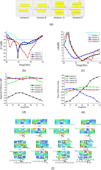
The initial antenna is a pair of MED, a rectangular coupling slot, and a rectangular microstrip line, as shown in Fig. 2a, antenna II is based on antenna I with a rectangular cut angle for the electric dipole, evolution of rectangular microstrip lines into T-shaped microstrip lines, and antenna III is side by side to add a pair of MED and the electric dipole with a triangular cutting angle, evolution of the T-shaped microstrip line into stepped microstrip line. Finally, antenna IV based on antenna III adds an elliptical perturbation, where the axis ratio is obtained by the formula (1), “a” is the long axis of the ellipse and “b” is the short axis of the ellipse:

Figure 2. (a) Configuration evolution of CP antennas, (b) a comparison of the reflection coefficient S11 of four antennas, (c) a comparison of the AR of four antennas, (d) a comparison of the magnitude difference of four antennas, (e) a comparison of the phase difference of four antennas, and (f) a comparison of the electric field vector distribution in T/4 of four antennas at 29.5 GHz.
Figure 2b shows that four antennas obtain a wide IBW, and from Fig. 2c, it can be seen that antenna II with a rectangular cut angle to the electric dipole shows the possibility of adjusting to CP, antenna III achieves an ARBW of 8% from 23.16 to 25.12 GHz, while antenna IV with the addition of elliptical perturbation expands the ARBW by 18.6% from 26.4 to 31.9 GHz. The CP principle of antenna realization is equal amplitude in horizontal and vertical directions and a phase difference of 90°. Simulation results of magnitude difference and phase difference of the four antennas are given in Fig. 2d and e. The results show that antenna I does not satisfy the principle of CP, antenna II has the possibility of realizing CP, antenna III has the performance of CP but with narrow ARBW, and antenna IV has equal amplitude and phase difference of −90°. ARBW is wider and the phase difference of antenna IV is −90°, so the designed antenna is a left-hand CP (LHCP) antenna.
Figure 2f simulates the distribution of the surface currents of the four antennas at 29.5 GHz at different times [Reference Ghosh, Islam and Das12]. The antenna I has no obvious rotation of surface current with time at t = 0 and t = T/4, antenna II has a relatively weak rotation of surface current with time at t = 0 and t = T/4, antenna III has a clockwise rotation of surface current with time at t = 0 and t = T/4, and antenna IV has a clockwise rotation of surface current with time at t = 0 and t = T/4 and strong rotation. The current distributions at t = T/2 and t = 3T/4 are similar to those at t = 0 and t = T/4, respectively, but in opposite directions. Combined with the working principle of CP, we can know that the antenna is an LHCP antenna, and after loading a pair of parasitic patches and adding elliptical perturbation, the ARBW is greatly expanded.
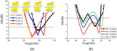
The four perturbation structures with the same equivalent area are compared, and the axial ratio results are shown in Fig. 3a; the circular polarization performance when the perturbation structure is elliptical under the same area is best to analyze the parameters of the elliptical long-axis radius, and the axial ratio results are shown in Fig. 3b; and the circular polarization performance is best when the long axis radius R 1 = 0.6 mm.

Figure 3. (a) AR of four cases and (b) AR of R 1.
Equivalent circuit model
In order to explain the working principle of the designed CP antenna more clearly, the equivalent circuit characteristics of the CP antenna are analyzed and its model is shown in Fig. 4a. The input port is equivalent to a resistor of 50 Ω, and the feeder line can be equivalent to an inductor L 1 and a series resistor R 1. The input signal passes through substrate 1, which can be equivalent to Tx line 1 and reaches the uppermost radiation patch through the rectangular slot and substrate 2. The rectangular slot is equivalent to the band-pass filter of the inductor (L 2) in series with the capacitor (C 2), and substrate 2 can be equivalent to Tx line 2. The metal via etched in substrate 2 can be equivalent to shunt inductance (L 3), in which the Tx line 2 is connected in parallel. The radiation patch of the antenna can be equivalent to the series connection of radiation resistance (Rrad), inductance (L 4), and capacitance (C 1). The overall circuit is drawn in Advanced Design System (ADS) software, and the parameters are as follows: L 1 = 0.6 pH, R 1 = 26.8 Ω, L 2 = 35.5 pH, C 2 = 29.7 fF, L 3 = 30.5 pH, Rrad = 63.8 Ω, C 1 = 8.4 fF, and L 4 = 3.4 fH. A good agreement between the simulated high-frequency structure simulator (HFSS) response and the numerically calculated advanced design system(ADS) result is observed in Fig. 4b.

Figure 4. (a) Equivalent circuit modeling and (b) results of ADS and HFSS.
The design of the antenna array
To obtain higher antenna gain in the application, a four-way microstrip power divider is designed [Reference Bai, Wang and Zou13], and four radiating elements are arranged into a periodic structure, which forms a planar 2 × 2 antenna array. The antenna is designed and optimized using Ansys full-wave electromagnetic simulation software. The power divider and the antenna array are shown in Fig. 5a, and the S-parameters of the power divider are shown in Fig. 5b. To investigate the effect of the spacing between the antenna units on the antenna array S11 and AR, a parametric analysis was performed, the results for antenna arrays S11 and AR corresponding to different unit spacing are shown in Fig. 5c. From Fig. 5b, it can be seen that S11 of input port #1 within the IBW of the antenna is lower than −15 dB, #2, #3, #4, and #5 the insertion loss is −6 dB between the four output ports and input port. The isolation between the output ports S23/S45/S25/S34 is lower than −25 dB, which indicates that the mutual coupling between the output ports is weak. The optimal cell spacing Dis = 9.5 mm can be obtained from Fig. 5c, and five circular holes with DD = 2 mm diameter were etched around the antenna for fixation; to reduce the loss, the compensation structure is designed in the feed network, that is the angle is cut, in which w, x, d, and m are indicated in Fig. 5a, and the best way to cut the angle can be obtained by formula (2):

Figure 5. (a) Antenna array and power divider, (b) S-parameters of the power divider, and (c) S11 for different parameters of Dis.
where w = 0.8 mm, h = 0.254 mm, and, therefore, the “m” is calculated at around 0.529.
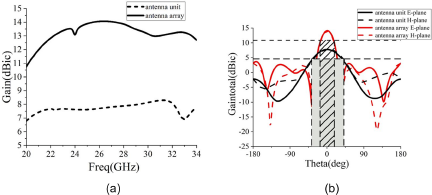
Next, the gain of the unit or array and the half-power beamwidth are compared, and the result is shown in Fig. 6. The gain increases and half-power beamwidths narrow of antenna arrays. Where the gain can be obtained by the formula (3), “D” is the directivity of the antenna, and “λ 0” is the wavelength:
 \begin{equation}{\textrm{Gain}} = 10{\textrm{lg}}\left\{ {4.5{*}\!\left({D \over {\lambda 0}}\right)\!{^\wedge{}}2} \right\}\end{equation}
Figure 6. (a) The gain of the antenna unit and array and (b) the HPBW of the antenna unit and array.
Simulation and measurement
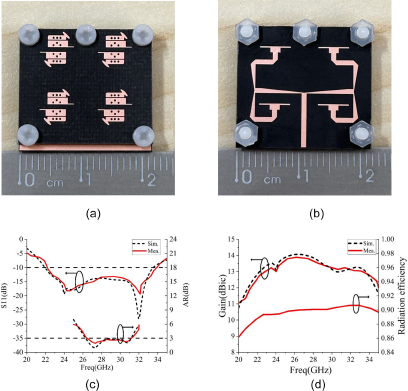
Figures 7a and b show the top view and bottom view of the antenna. Respectively, simulations and measurements were performed for the proposed antenna. Figure 7c shows the simulated and measured S11 as well as the AR of the antenna array. It can be seen that the measured and simulated curves of the antenna match well, and a relative bandwidth of 41.6% (22.28–33.97 GHz) and an ARBW of 16.6% (26.42–31.21 GHz) are obtained. The measured peak gain of the antenna reaches 13.89 dBic as seen in Fig. 7d. The radiation efficiency of the antenna is higher than 89% in the whole operating band. The radiation efficiency can be obtained by the formula (4), where “D” and “Ap” are the directivity and aperture size of the antenna and “λ 0” is the wavelength:
 \begin{equation}{\text{ Efficiency}} = \frac{{D\lambda 0^\wedge{} 2}}{{4\pi Ap}}\end{equation}
Figure 7. The fabricated antenna and the simulated and measured results. (a) The top view, (b) the bottom view, (c) S11 and AR, and (d) gain and radiation efficiency.
Figures 8a and b give the measured and simulated directional diagrams of the xoz-plane and yoz-plane at 27 GHz and 31.5 GHz. It can be seen that the simulated and measured radiation patterns coincide with each other. The main polarization is LHCP, the right-hand CP (RHCP) level is low, and the measured cross-polarization is below −20 dB in the whole operating band. The antenna achieves a stable radiation performance.

Figure 8. xoz-plane and yoz-plane radiation patterns (a) at 27 GHz and (b) at 31.5 GHz.
To better illustrate the value of the antenna array designed in this paper for millimeter-wave applications, Table 1 [Reference Xu, Li, Liu, Zhou and Wei14–Reference Midya, Ghosh and Mitra17] shows the comparison of the proposed antenna with other CP antenna arrays in terms of IBW, ARBW, gain, shape, and size. As can be seen from Table 1, the antenna array designed in this paper has significant advantages over arrays of the same size, both in terms of IBW and ARBW, and ensures gain and overall size.
Table 1. Performance comparison with the proposed antenna

Conclusion
This paper designs and processes a broadband CP antenna unit and array for millimeter-wave applications. The results of the planar 2 × 2 antenna array measurements show that when S11 < −10 dB, the measured IBW is 41.6% from 22.28 to 33.97 GHz. The measured 3 dB ARBW is 16.6% from 26.42 to 31.21 GHz. The peak gain is 13.89 dBic, and the radiation efficiency is greater than 89% in the operating bandwidth. The antenna array is LHCP, with obvious main polarization LHCP and low cross-polarization RHCP level greater than −20 dB, and has good radiation characteristics.
Funding statement
This work was supported in part by the Shandong Natural Science Foundation of ZR2023MF038 and the National Natural Science Foundation of China (61701278).
Competing interests
The author declares that there is no conflict of interest regarding the publication of this paper.

Yue Xie was born in Xingtai, China, in 1997. She received a B.E. degree in Electronic Information Engineering from Qufu Normal University, Qufu China, in 2020. She is currently pursuing an M.E. degree at Qufu Normal University. Her current research interests include 5G millimeter-wave broadband circularly polarized antenna and arrays.

Jianping Zhao is a professor and supervisor of master’s students. In 1981, he entered the Physics Department of Qufu Normal University, and in 1988, he pursued a master’s degree in Radio and Information Engineering at Wuhan University. His current research interests include wireless communication technology and the design of electronic technology applications.

Yurong Sun was born in Yantai, China, in 1997, and graduated from Qufu Normal University in 2020 with a B.S. degree in Communication Engineering and graduated from Qufu Normal University in 2023 with a M.S. degree in Electronic Information Engineering. Her research interests include millimeter-wave broadband magnetoelectric dipole circularly polarized antennas and arrays.

Juan Xu was born in 1982 and graduated from Nanjing University of Science and Technology in 2016 with a Ph.D. in Electronic Science and Technology. She is currently an associate professor of Cyber Science and Engineering, at Qufu Normal University. Her research interests mainly include microwave/millimeter wave circuits and systems, integrated circuits, antenna array optimization and beam forming, multifunctional electromagnetic metasurface, and terahertz biosensing.


